US3083340A - Phase and frequency control systems for discriminators and the like - Google Patents
Phase and frequency control systems for discriminators and the like Download PDFInfo
- Publication number
- US3083340A US3083340A US796690A US79669059A US3083340A US 3083340 A US3083340 A US 3083340A US 796690 A US796690 A US 796690A US 79669059 A US79669059 A US 79669059A US 3083340 A US3083340 A US 3083340A
- Authority
- US
- United States
- Prior art keywords
- signal
- frequency
- phase
- phase difference
- function
- Prior art date
- Legal status (The legal status is an assumption and is not a legal conclusion. Google has not performed a legal analysis and makes no representation as to the accuracy of the status listed.)
- Expired - Lifetime
Links
- 230000010363 phase shift Effects 0.000 description 17
- 230000008901 benefit Effects 0.000 description 4
- 230000008859 change Effects 0.000 description 3
- 230000008878 coupling Effects 0.000 description 2
- 238000010168 coupling process Methods 0.000 description 2
- 238000005859 coupling reaction Methods 0.000 description 2
- 230000004048 modification Effects 0.000 description 2
- 238000012986 modification Methods 0.000 description 2
- 101150087426 Gnal gene Proteins 0.000 description 1
- 241000283160 Inia Species 0.000 description 1
- 239000003990 capacitor Substances 0.000 description 1
- 238000010586 diagram Methods 0.000 description 1
- 238000004519 manufacturing process Methods 0.000 description 1
- 238000000034 method Methods 0.000 description 1
- 230000008520 organization Effects 0.000 description 1
Images

Classifications
-
- H—ELECTRICITY
- H03—ELECTRONIC CIRCUITRY
- H03L—AUTOMATIC CONTROL, STARTING, SYNCHRONISATION OR STABILISATION OF GENERATORS OF ELECTRONIC OSCILLATIONS OR PULSES
- H03L7/00—Automatic control of frequency or phase; Synchronisation
- H03L7/02—Automatic control of frequency or phase; Synchronisation using a frequency discriminator comprising a passive frequency-determining element
Definitions
- the control system acts to vary the frequency of these signals for adjusting the phase.
- a preferred embodiment of the invention comprises a control system having a signal supply means for pro viding a variable frequency signal.
- the control system also includes a signal translating means responsive to the variable frequency signal for providing comparison signals, having a phase difference which is a function of the frequency of the variable frequency signal.
- Circuit means are provided for comparing the comparison signals and for generating an output signal which is a function of the phase difference between the comparison signals.
- the aforementioned circuit means is a phase detector which is responsive to the phase difference between the comparison signals, and generates an output signal whose magnitude and polarity is representative of the phase difference.
- Means, comprising an input terminal are provided for coupling a control signal, used for adjusting the phase difference to a predetermined value, to the control system.
- control system includes means, comprising a difference amplifier, which is coupled to the input terminal and the phase detector, and re sponds to the control signal and the output signal for providing tuning signals.
- the tuning signal varies the frequency of the variable frequency signal until the magnitude of the output signal equals that of the control signal, at which time the phase difference between the comparison signals is adjusted to the selected difierence.
- the control system makes use of a frequency discriminator.
- An important benefit gained from this frequency discriminator is its ability to operate over a Wide band of frequencies, the upper and lower frequency limits being in the ratio of two to one. It also features simplicity of design and operational reliability.
- another object of this invention is to provide a frequency discriminator, comprising a signal translating means which responds to a variable frequency signal, for providing comparison signals having a phase diiference 3,083,340 Patented Mar. 26, 1963 which is a function of the frequency of the variable frequency signal.
- the signal translating means will comprise a delay line having two taps from which signals having a specific phase difference may be derived.
- the frequency discriminator also includes circuit means, comprising a phase detector for comparing the phase difference between the comparison signals and generating an output signal which is a function of the phase dilference.
- FIGURE 1 is a block diagram of a control system embodying the principles of the present invention.
- FIGURE 2 shows a portion of the FIGURE 1 control system which comprises a frequency discriminator.
- FIGURE 1 control system can function, without modification, to control the frequency of a variable frequency signal generator, or the phase difference between signals. Whether the control system performs one function or the other depends on the viewpoint one takes, or the significance attached to the control signal applied to the system.
- the control system 10 includes a signal supply means 11 for providing a variable frequency signal.
- the signal supply means 11 may comprise, for example, a controlled variable frequency signal generator constructed as a reactance tube oscillator, or an oscillator whose frequency is varied by adjusting the DC. voltage applied to a Varicap capacitor. Both of these circuits are well known in the art and will not be described in detail.
- the control system 10 also includes means, comprising a phase shift network 12, which is coupled to the signal supply means 11, and responds to the signals supplied from the signal supply means 11 for providing comparison signals having a phase difference which is a function of the frequency of the applied signal.
- the phase shift network 12 may comprise, for example, a multi-tapped delay line or a wave guide, depending on the frequency used. It is well known, in either case, that the phase of the signals obtained at adjacent taps, in the delay line or the wave guide is a function of the frequency of the signal being translated therein.
- the phase shift network 12 includes a plurality of output terminals designated 13, 14, 15 and 16, from each of which can be obtained a comparison signal whose phases are related. In this discussion, the comparison signals will be derived from the adjacent terminals 13 and 14.
- the arrows cou pling the output terminals 13 through 16 represent signals taken from the phase shift network for use in external equipment that require a plurality of signals having related phases.
- phase detector 18 is provided for comparing the comparison signals.
- the phase detector 18 is coupled to terminals 1 3 and 14 of the phase shift network "12 for receiving the comparison signals.
- Phase detector 18 is conventional in its design and operation. It generates an output signal whose magnitude and polarity .is reprepling the centerpoint to ground.
- resistor 20' is'unnecessary if terminal 19 is coupled to a variable'supply voltage whose amplitude and polarity is representative of the desired phase difference.
- the phase control system includes means coupled to the phase detector and the input terminal .19, which is responsive to the output signal and the controlsignal for providing the tuning signal which is a function of the control and tuning signals.
- This means may, for example, comprise a differ ence amplifier .21 whose. output circuit means is coupled to the signal supply means 11.
- phase difference d bj the magnitude of which is determined by a control signal, designated Ec," applied to terminal 19.
- Ec a control signal
- Be is related to dqb through its relationship to the output signal E from the phase detector 18.
- the relationship between E and dq5 is determined by calibrating the phase detector output E by applying to the input signals having known phase differences.
- Ec and E are compared in the difference amplifier 21 and 'a tuning signal, designated V, is generated, where V is a function of the difference between Be and E. See FIGURE 1 where g (V) denotes function. It will also be shown that V is substantially zero at any adjusted value of dqb. Since we have assumed, as an initial condition, that the control system 10 is adjusted to a phase difference, it follows that initially V is substantially zero. V
- the magnitude of the control signal E is changed.
- the previously mentioned zero condition is destroyed and a signal V is developed.
- the signal V acts as a tuning signal to change the frequency of the signal supply means 11 inia direction which, as will be seen hereinafter, tends to decrease the magnitude of V.
- the output frequency, f, of the signal supply means, shown as being equal to a function of V is applied to the input of the phase shift network 12.
- the phase detector 18 acts upon this difference in phase and generates, in a conventional manner the signal E which is a function of the phase difference. See FIGURE 1.
- the magnitude of E is also varying as the frequency of the signal from the signal supply means is varied. It is varying in a direction tending to equal the magnitude of the control signal Ec.
- the tuningsi'gnal V which is a function of the difference between the signal E and the control signal E0 tends toward zero.
- the signal supply means 11 is supplying a signal to the phase shift network 12 whose frequency is such that the phase difference d between the comparison signals derived from terminals 13 and 14 is adjustedessentially to the predetermined value and the difierence between the signal E and-the control signal E0 is essentially zero.
- the control system 10 acts as a phase control system or a frequency control system depending on the viewpoint.
- the phase and frequency of a signal are considered to be variables of the signal.
- the phase and frequency of the signal from the signal supply means .11 are related in the phase shift network.
- the control of either variable may be the objective sought.
- the control voltage Ec represented an independently selected difference in phase between the comparison signals 13 and 14 and the frequency of the signal obtained from the signal supply means 11 was varied under the control of the control signal Ec until a selected phase difference was obtained.
- the control signal Ec denotes, or represents a specific frequency
- the control system 10 utilizes the phase difference 11, under the control of the control signal Ec? foradjusting the frequency of the signal obtained from the signal supply means.
- FIGURE 2 of the drawings there is shown a frequency discriminator generally designated 22, which comprises elements of the previously described control system 10. These elements comprise the phase shift network 12 and the phase detector 18. It has been previously mentioned that the output signal from the phase detectoris a signal whose magnitude and polarity is representative of the phase difference between the comparison signals applied to its input.
- the frequency discriminator 22 recognition is made of the fact that the phase difierence between two taps on a phase shift network, is related to the frequency of the signal applied to the network. In this application the frequency is shown as a function of time, g(t).
- the discriminator 22 first develops a pair of comparison signals whose phase difference is a function of the frequencies of these signals, and then compares this phase difference for developing an output signal whose magnitude and polarity is representative of the phase difference, and consequently of the frequency.
- phase difference is varied. This phase difference is unambiguous until a frequency is reached 7 where the phase difference developed is exactly 180 out of phase with the phase difference developed for an earlier signal. At this point an ambiguity arises because there is no way of determining whether the phase difference is due to the earlier or later signal. However, this shift can represent a two to one difference in frequency, an extremely broad bandfor frequency discriminators.
- a phase control system comprising; signal supply means :for providing a variable frequency signal; means responsive to the variable frequency signal for providing comparison signals having a phase difference which is a function of the frequency of the variable frequency signal; circuit means for comparing the comparison signals and generating an output signal that is a function of the phase difference between the comparison signals; means for providing a control signal for adjusting the phase difference to a predetermined value; and means responsive to the control signal and the output signal for providing a tuning signal which is a function of the control and the output signals for varying the frequency of the variable frequency signal supply means until the comparison signals have attained the preselected value.
- a phase control system comprising: signal supply means for providing a variable frequency signal; a phase shift network coupled to said signal supply means for providing comparison signals having a phase difference which is a function of the frequency of the variable frequency signal; a phase detector coupled to said phase shift network for comparing the phase difference between the comparison signals and generating an output signal whose magnitude and polarity is a function of the phase differenc'e; means for providing a control signal for adjusting the phase difference to a predetermined value; a difference amplifier responsive to the output signal and the control signal for generating a tuning signal whose magnitude is a function of the difference of the magnitudes of output and the control signals, the tuning signal varying the frequency of the variable frequency signal supply means to adjust the phase diiference between the comparison signals.
- phase shift network comprises a signal translating means having a plurality of output circuits, each of the output circuits providing a comparison signal.
- phase shift network is a multi-tapped delay line, the comparison signals being provided at the taps of said delay line.
- a frequency control system comprising: signal supply means for providing a variable frequency signal; means responsive to the variable frequency signal for pro viding comparison signals having a phase difference which is a function of the frequency of the variable frequency signal; circuit means for comparing the comparison signals and generating an output signal that is a function of the phase diiference between the comparison signals; means for providing a control signal for adjusting the frequency of the variable frequency signal to a predetermined va-lue; and means responsive to the control signal and the output signal for providing a tuning signal which is a function of the control and output signal for varying the frequency of the variable frequency signal supply means until it has the preselected value.
- a frequency discriminator for a broad frequency band of signals comprising: siginal translating means comprising a multi-tapped delay line adapted to receive a signal having a frequency in the broad frequency band of signals for providing comparison signals at the taps of said multi-tap delay line having a phase difference that is a function of the frequency of the received signal and a phase detector coupled to said signal translating means for comparing the phase difference between the comparison signals and generating an output signal the magnitude and polarity of which are a function of the phase difference.
- a phase control system comprising: a signal supply means for supplying a variable frequency signal; means coupled to said signal supply means for receiving a variable frequency signal therefrom for providing comparison signals having a phase difference which is a function of the frequency of the received signal; means for generating a control signal for selecting a phase difference to which the comparison signals are to be adjusted; means coupled to the comparison signals for generating an output signal which is a function of the phase difference of the comparison signals; and comparison means coupled to said last-mentioned means and said selection means responsive to said output signal and said control signal for providing a tuning signal for tuning said variable frequency signal supply means for varying the frequency of the variable frequency signal.
- a system for controlling a signal variable comprising: a signal supply means for supplying a frequency tunable signal; means coupled to said signal supply means and responsive to said tunable frequency signal for providing comparison signals having a phase difference which is a function of the frequency of the tunable frequency signal; means for selecting the magnitude of the variable to be controlled; and means coupled to the comparison signals for providing an output signal which is a function of the phase difference of the comparison signals; and means coupled to the output signal and the selection means for providing a tuning signal for varying the frequency of said signal supply means.
Landscapes
- Stabilization Of Oscillater, Synchronisation, Frequency Synthesizers (AREA)
Description
March 26, 1963 Filed March 2, 1959 B. K. NELSON PHASE AND FREQUENCY =CONTROL SYSTEMS FOR DISCRIMINATOR'S AND "THE LIKE 2 Sheets-Sheet 1 12 SIGNAL SUPPLY c PQHAsEQ SHIFT gErwgRxp 2 MEANS is m 1'5 1'6 Q Q l V=g(E-Ec) DIFFERENCE E=g(d) PHASE {0 AMPbIFlER v DETECTOR l9 9 E0 45 -B I BRUCE K. NELSON INVENTOR.
BY fl/Mfl/ 1/ ATTORNEYSv Marh L2 6 Filed March 2 1:959
1963 B 5K NELSON 2 Sheets-Sheet 2 f=g(1) -O PHASE SHIFT NETWORK Q 8 r22 d =g(f) PHASE DETECTOR BRUCE K. NELSON INVENTOR. flt 7 W MGZW ATTORNEYS 3,063,340 PHASE AND FREQUENCY CONTROL SYSTEMS FOR DISCRIMINATORS AND THE LIKE Bruce K. Nelson, Concord, Mass, assignor to AVCO Manufacturing Corporation, Cincinnati, Ohio, a corporation of Delaware Fiied Mar. 2, 1959, Ser. No. 7%,690 11 Claims. (Cl. 329-137) This invention relates to a system for controlling the phase difference between signals, or for controlling the frequency of a variable frequency signal generator. In both applications, this invention makes use of comparison signals whose phase difference is a function of their frequency.
It is an object of the invention to provide a control system for controlling the phase difference between two or more related signals.
It is another object of the invention to provide a control system for controlling the frequency of a variable frequency signal generator.
It is still another object of the invention to provide a control system for adjusting the phase difference of signals, whose phases are a function of the frequency of these signals. The control system acts to vary the frequency of these signals for adjusting the phase.
It is still another object of the invention to provide a frequency discriminator which operates over a wide band of frequencies.
It is another object of the invention to provide a frequency discriminator which first generates comparison signals having a phase difference which is a function of their frequency and then develops an output signal which is representative of the frequency of these signals.
A preferred embodiment of the invention comprises a control system having a signal supply means for pro viding a variable frequency signal. The control system also includes a signal translating means responsive to the variable frequency signal for providing comparison signals, having a phase difference which is a function of the frequency of the variable frequency signal. Circuit means are provided for comparing the comparison signals and for generating an output signal which is a function of the phase difference between the comparison signals. The aforementioned circuit means is a phase detector which is responsive to the phase difference between the comparison signals, and generates an output signal whose magnitude and polarity is representative of the phase difference. Means, comprising an input terminal, are provided for coupling a control signal, used for adjusting the phase difference to a predetermined value, to the control system. Finally, the control system includes means, comprising a difference amplifier, which is coupled to the input terminal and the phase detector, and re sponds to the control signal and the output signal for providing tuning signals. The tuning signal varies the frequency of the variable frequency signal until the magnitude of the output signal equals that of the control signal, at which time the phase difference between the comparison signals is adjusted to the selected difierence.
In performing the control function, the control system makes use of a frequency discriminator. An important benefit gained from this frequency discriminator is its ability to operate over a Wide band of frequencies, the upper and lower frequency limits being in the ratio of two to one. It also features simplicity of design and operational reliability.
' Therefore, another object of this invention is to provide a frequency discriminator, comprising a signal translating means which responds to a variable frequency signal, for providing comparison signals having a phase diiference 3,083,340 Patented Mar. 26, 1963 which is a function of the frequency of the variable frequency signal. Normally the signal translating means will comprise a delay line having two taps from which signals having a specific phase difference may be derived. The frequency discriminator also includes circuit means, comprising a phase detector for comparing the phase difference between the comparison signals and generating an output signal which is a function of the phase dilference. Since the phase dilference is a function of the frequency of the signal applied to the signal translating means, it follows that the output signal, being a function of the phase difference, is also a function of the frequency. I The novel features that are considered characteristic of the invention are set forth in the appended claims; the invention itself, however, both as to its organization and method of operation, together with additional objects and advantages thereof, will best be understood from the following description of a specific embodiment when read in conjunction with the accompanying drawings, in which: FIGURE 1 is a block diagram of a control system embodying the principles of the present invention; and
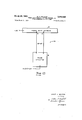
FIGURE 2 shows a portion of the FIGURE 1 control system which comprises a frequency discriminator.
Description of the FIGURE 1 Control System It will become clear hereinafter that the FIGURE 1 control system can function, without modification, to control the frequency of a variable frequency signal generator, or the phase difference between signals. Whether the control system performs one function or the other depends on the viewpoint one takes, or the significance attached to the control signal applied to the system.
Referring to FIGURE 1 of the drawings, there is shown a control system, generally designated 10 which embodies the principles of the present invention. The control system 10 includes a signal supply means 11 for providing a variable frequency signal. The signal supply means 11 may comprise, for example, a controlled variable frequency signal generator constructed as a reactance tube oscillator, or an oscillator whose frequency is varied by adjusting the DC. voltage applied to a Varicap capacitor. Both of these circuits are well known in the art and will not be described in detail.
The control system 10 also includes means, comprising a phase shift network 12, which is coupled to the signal supply means 11, and responds to the signals supplied from the signal supply means 11 for providing comparison signals having a phase difference which is a function of the frequency of the applied signal. The phase shift network 12 may comprise, for example, a multi-tapped delay line or a wave guide, depending on the frequency used. It is well known, in either case, that the phase of the signals obtained at adjacent taps, in the delay line or the wave guide is a function of the frequency of the signal being translated therein. The phase shift network 12 includes a plurality of output terminals designated 13, 14, 15 and 16, from each of which can be obtained a comparison signal whose phases are related. In this discussion, the comparison signals will be derived from the adjacent terminals 13 and 14. The arrows cou pling the output terminals 13 through 16 represent signals taken from the phase shift network for use in external equipment that require a plurality of signals having related phases.
A phase detector 18 is provided for comparing the comparison signals. The phase detector 18 is coupled to terminals 1 3 and 14 of the phase shift network "12 for receiving the comparison signals. Phase detector 18 is conventional in its design and operation. It generates an output signal whose magnitude and polarity .is reprepling the centerpoint to ground. Manifestly, resistor 20' is'unnecessary if terminal 19 is coupled to a variable'supply voltage whose amplitude and polarity is representative of the desired phase difference. Finally, the phase control system includes means coupled to the phase detector and the input terminal .19, which is responsive to the output signal and the controlsignal for providing the tuning signal which is a function of the control and tuning signals. This means may, for example, comprise a differ ence amplifier .21 whose. output circuit means is coupled to the signal supply means 11.
Operation of the Figure 1 Control System I The operation of the FIGURE 1 control system will be discussed with regard to adjusting the phase difference, designated d, between the comparisonsignals derived from terminals 13 and 14 of the phase shift network 12.
Initially, it will be assumed that the control system 10 is adjusted to a phase difference d bj the magnitude of which is determined by a control signal, designated Ec," applied to terminal 19. As will be seen hereinafter, Be is related to dqb through its relationship to the output signal E from the phase detector 18. The relationship between E and dq5 is determined by calibrating the phase detector output E by applying to the input signals having known phase differences.
Ec and E are compared in the difference amplifier 21 and 'a tuning signal, designated V, is generated, where V is a function of the difference between Be and E. See FIGURE 1 where g (V) denotes function. It will also be shown that V is substantially zero at any adjusted value of dqb. Since we have assumed, as an initial condition, that the control system 10 is adjusted to a phase difference, it follows that initially V is substantially zero. V
When it is desired to change the phase difference between the comparison signals, the magnitude of the control signal E is changed. The previously mentioned zero condition is destroyed and a signal V is developed. The signal V acts as a tuning signal to change the frequency of the signal supply means 11 inia direction which, as will be seen hereinafter, tends to decrease the magnitude of V. The output frequency, f, of the signal supply means, shown as being equal to a function of V is applied to the input of the phase shift network 12.
' The comparison signals derived from the phase shift net work 12 will now have a phase difference that is varying,
in synchronism, with the rate of change of frequency of the signal from the signal supply means 1-1. The phase detector 18 acts upon this difference in phase and generates, in a conventional manner the signal E which is a function of the phase difference. See FIGURE 1. The magnitude of E is also varying as the frequency of the signal from the signal supply means is varied. It is varying in a direction tending to equal the magnitude of the control signal Ec. Clearly, therefore, the tuningsi'gnal V which is a function of the difference between the signal E and the control signal E0 tends toward zero. When the tuning signal V" has the proper value, the signal supply means 11 is supplying a signal to the phase shift network 12 whose frequency is such that the phase difference d between the comparison signals derived from terminals 13 and 14 is adjustedessentially to the predetermined value and the difierence between the signal E and-the control signal E0 is essentially zero.
It has been previously mentioned that the control system 10 acts as a phase control system or a frequency control system depending on the viewpoint. For purposes of this discussion the phase and frequency of a signal are considered to be variables of the signal. In the control system 10 the phase and frequency of the signal from the signal supply means .11 are related in the phase shift network. However, in accordance with this invention, the control of either variable may be the objective sought. For example, in the operation just discussed, the control voltage Ec represented an independently selected difference in phase between the comparison signals 13 and 14 and the frequency of the signal obtained from the signal supply means 11 was varied under the control of the control signal Ec until a selected phase difference was obtained. However, if the control signal Ec denotes, or represents a specific frequency, the control system 10 utilizes the phase difference 11, under the control of the control signal Ec? foradjusting the frequency of the signal obtained from the signal supply means.
Description and Operation of the FIGURE 2 Frequency Discriminator Referring to FIGURE 2 of the drawings, there is shown a frequency discriminator generally designated 22, which comprises elements of the previously described control system 10. These elements comprise the phase shift network 12 and the phase detector 18. It has been previously mentioned that the output signal from the phase detectoris a signal whose magnitude and polarity is representative of the phase difference between the comparison signals applied to its input. In the frequency discriminator 22, recognition is made of the fact that the phase difierence between two taps on a phase shift network, is related to the frequency of the signal applied to the network. In this application the frequency is shown as a function of time, g(t). Accordingly, in performing frequency discrimination, the discriminator 22 first develops a pair of comparison signals whose phase difference is a function of the frequencies of these signals, and then compares this phase difference for developing an output signal whose magnitude and polarity is representative of the phase difference, and consequently of the frequency.
-As the frequency of the signal applied to the phase networkis varied, the phase difference is varied. This phase difference is unambiguous until a frequency is reached 7 where the phase difference developed is exactly 180 out of phase with the phase difference developed for an earlier signal. At this point an ambiguity arises because there is no way of determining whether the phase difference is due to the earlier or later signal. However, this shift can represent a two to one difference in frequency, an extremely broad bandfor frequency discriminators.
The various features and advantages of the invention are thought to be clear from the foregoing description. Various other features and advantages not specifically enumerated will undoubtedly occur to those versed in the art, as likewise will many variations and modifications of the preferred embodiment illustrated, all of which may be achieved without departing from the spirit and scope of the invention as defined by the following claims.
I claim: a
1. A phase control system comprising; signal supply means :for providing a variable frequency signal; means responsive to the variable frequency signal for providing comparison signals having a phase difference which is a function of the frequency of the variable frequency signal; circuit means for comparing the comparison signals and generating an output signal that is a function of the phase difference between the comparison signals; means for providing a control signal for adjusting the phase difference to a predetermined value; and means responsive to the control signal and the output signal for providing a tuning signal which is a function of the control and the output signals for varying the frequency of the variable frequency signal supply means until the comparison signals have attained the preselected value.
2. A phase control systemcomprising: signal supply means for providing a variable frequency signal; a phase shift network coupled to said signal supply means for providing comparison signals having a phase difference which is a function of the frequency of the variable frequency signal; a phase detector coupled to said phase shift network for comparing the phase difference between the comparison signals and generating an output signal whose magnitude and polarity is a function of the phase differenc'e; means for providing a control signal for adjusting the phase difference to a predetermined value; a difference amplifier responsive to the output signal and the control signal for generating a tuning signal whose magnitude is a function of the difference of the magnitudes of output and the control signals, the tuning signal varying the frequency of the variable frequency signal supply means to adjust the phase diiference between the comparison signals.
3. A phase control system as described in claim 2 in which said phase shift network comprises a signal translating means having a plurality of output circuits, each of the output circuits providing a comparison signal.
4. A phase control system as described in claim 2 in which said phase shift network is a multi-tapped delay line, the comparison signals being provided at the taps of said delay line.
5. A frequency control system comprising: signal supply means for providing a variable frequency signal; means responsive to the variable frequency signal for pro viding comparison signals having a phase difference which is a function of the frequency of the variable frequency signal; circuit means for comparing the comparison signals and generating an output signal that is a function of the phase diiference between the comparison signals; means for providing a control signal for adjusting the frequency of the variable frequency signal to a predetermined va-lue; and means responsive to the control signal and the output signal for providing a tuning signal which is a function of the control and output signal for varying the frequency of the variable frequency signal supply means until it has the preselected value.
6. A frequency discriminator for a broad frequency band of signals comprising: siginal translating means comprising a multi-tapped delay line adapted to receive a signal having a frequency in the broad frequency band of signals for providing comparison signals at the taps of said multi-tap delay line having a phase difference that is a function of the frequency of the received signal and a phase detector coupled to said signal translating means for comparing the phase difference between the comparison signals and generating an output signal the magnitude and polarity of which are a function of the phase difference.
7. A phase control system comprising: a signal supply means for supplying a variable frequency signal; means coupled to said signal supply means for receiving a variable frequency signal therefrom for providing comparison signals having a phase difference which is a function of the frequency of the received signal; means for generating a control signal for selecting a phase difference to which the comparison signals are to be adjusted; means coupled to the comparison signals for generating an output signal which is a function of the phase difference of the comparison signals; and comparison means coupled to said last-mentioned means and said selection means responsive to said output signal and said control signal for providing a tuning signal for tuning said variable frequency signal supply means for varying the frequency of the variable frequency signal.
8. A phase control system as described in claim 7 in which said selection means comprises a variable resistance means having a voltage gradient along the extent thereof.
9. A phase control system as described in claim 7 in which said selection means comprises a signal supply means for providing a signal which is representative of a selected phase difierence.
10. A system for controlling a signal variable comprising: a signal supply means for supplying a frequency tunable signal; means coupled to said signal supply means and responsive to said tunable frequency signal for providing comparison signals having a phase difference which is a function of the frequency of the tunable frequency signal; means for selecting the magnitude of the variable to be controlled; and means coupled to the comparison signals for providing an output signal which is a function of the phase difference of the comparison signals; and means coupled to the output signal and the selection means for providing a tuning signal for varying the frequency of said signal supply means.
11. A control system as described in claim 10 in which said selection means comprises a signal supply means for providing a control signal which is representative of a selected value of the variable being controlled.
References Cited in the file of this patent UNITED STATES PATENTS 2,279,659 Crosby Apr. 14, 1942 2,279,660 Crosby Apr. 14, 1942 2,775,700 Ring Dec. 25, 1956 2,805,334 Cayzac Sept. 3, 1957 2,844,652 Pinet July 22, 1958 2,930,842 Leyton Mar. 29, 1960 2,935,609 Rabin et al May 3, 1960
Claims (1)
1. A PHASE CONTROL SYSTEM COMPRISING; SIGNAL SUPPLY MEANS FOR PROVIDING A VARIABLE FREQUENCY SIGNAL; MEANS RESPONSIVE TO THE VARIABLE FREQUENCY SIGNAL FOR PROVIDING COMPARISON SIGNALS HAVING A PHASE DIFFERENCE WHICH IS A FUNCTION OF THE FREQUENCY OF THE VARIABLE FREQUENCY SIGNAL; CIRCUIT MEANS FOR COMPARING THE COMPARISON SIGNALS AND GENERATING AN OUTPUT SIGNAL THAT IS A FUNCTION OF THE PHASE DIFFERENCE BETWEEN THE COMPARISON SIGNALS; MEANS FOR PROVIDING A CONTROL SIGNAL FOR ADJUSTING THE PHASE DIFFERENCE TO A PREDETERMINED VALUE; AND MEANS RESPONSIVE TO THE CONTROL SIGNAL AND THE OUTPUT SIGNAL FOR PROVIDING A TUNING SIGNAL WHICH IS A FUNCTION OF THE CONTROL AND THE OUTPUT SIGNALS FOR VARYING THE FREQUENCY OF THE VARIABLE FREQUENCY SIGNAL SUPPLY MEANS UNTIL THE COMPARISON SIGNALS HAVE ATTAINED THE PRESELECTED VALUE.
Priority Applications (1)
| Application Number | Priority Date | Filing Date | Title |
|---|---|---|---|
| US796690A US3083340A (en) | 1959-03-02 | 1959-03-02 | Phase and frequency control systems for discriminators and the like |
Applications Claiming Priority (1)
| Application Number | Priority Date | Filing Date | Title |
|---|---|---|---|
| US796690A US3083340A (en) | 1959-03-02 | 1959-03-02 | Phase and frequency control systems for discriminators and the like |
Publications (1)
| Publication Number | Publication Date |
|---|---|
| US3083340A true US3083340A (en) | 1963-03-26 |
Family
ID=25168803
Family Applications (1)
| Application Number | Title | Priority Date | Filing Date |
|---|---|---|---|
| US796690A Expired - Lifetime US3083340A (en) | 1959-03-02 | 1959-03-02 | Phase and frequency control systems for discriminators and the like |
Country Status (1)
| Country | Link |
|---|---|
| US (1) | US3083340A (en) |
Cited By (6)
| Publication number | Priority date | Publication date | Assignee | Title |
|---|---|---|---|---|
| US3528033A (en) * | 1968-08-07 | 1970-09-08 | Sperry Rand Corp | Sweep rate controlled frequency swept oscillator |
| US3621405A (en) * | 1968-05-28 | 1971-11-16 | Itek Corp | Sinusoidal converter |
| US3852681A (en) * | 1971-10-01 | 1974-12-03 | Philips Corp | Variable frequency oscillator systems |
| US3944938A (en) * | 1973-08-16 | 1976-03-16 | Compagnie Industrielle Des Telecommunications Cit-Alcatel | Phase correlator |
| US3992679A (en) * | 1974-07-05 | 1976-11-16 | Sony Corporation | Locked oscillator having control signal derived from output and delayed output signals |
| US6505141B2 (en) * | 1998-07-09 | 2003-01-07 | Taylor Hobson Limited | Transducer circuit |
Citations (7)
| Publication number | Priority date | Publication date | Assignee | Title |
|---|---|---|---|---|
| US2279659A (en) * | 1937-04-13 | 1942-04-14 | Rca Corp | Frequency modulator |
| US2279660A (en) * | 1937-04-13 | 1942-04-14 | Rca Corp | Wave length modulation system |
| US2775700A (en) * | 1953-10-01 | 1956-12-25 | Bell Telephone Labor Inc | Frequency stabilized oscillator |
| US2805334A (en) * | 1953-11-27 | 1957-09-03 | Philips Corp | Frequency discriminator circuit arrangement for ultra high-frequency oscillations |
| US2844652A (en) * | 1952-10-03 | 1958-07-22 | Pinet Andre Eugene | Switch device for multiplex channel transmission receivers |
| US2930842A (en) * | 1955-07-29 | 1960-03-29 | Rca Corp | Phase detecting and automatic phasing circuitry especially for color television apparatus |
| US2935609A (en) * | 1957-08-21 | 1960-05-03 | Sperry Rand Corp | Pre-trigger generator |
-
1959
- 1959-03-02 US US796690A patent/US3083340A/en not_active Expired - Lifetime
Patent Citations (7)
| Publication number | Priority date | Publication date | Assignee | Title |
|---|---|---|---|---|
| US2279659A (en) * | 1937-04-13 | 1942-04-14 | Rca Corp | Frequency modulator |
| US2279660A (en) * | 1937-04-13 | 1942-04-14 | Rca Corp | Wave length modulation system |
| US2844652A (en) * | 1952-10-03 | 1958-07-22 | Pinet Andre Eugene | Switch device for multiplex channel transmission receivers |
| US2775700A (en) * | 1953-10-01 | 1956-12-25 | Bell Telephone Labor Inc | Frequency stabilized oscillator |
| US2805334A (en) * | 1953-11-27 | 1957-09-03 | Philips Corp | Frequency discriminator circuit arrangement for ultra high-frequency oscillations |
| US2930842A (en) * | 1955-07-29 | 1960-03-29 | Rca Corp | Phase detecting and automatic phasing circuitry especially for color television apparatus |
| US2935609A (en) * | 1957-08-21 | 1960-05-03 | Sperry Rand Corp | Pre-trigger generator |
Cited By (6)
| Publication number | Priority date | Publication date | Assignee | Title |
|---|---|---|---|---|
| US3621405A (en) * | 1968-05-28 | 1971-11-16 | Itek Corp | Sinusoidal converter |
| US3528033A (en) * | 1968-08-07 | 1970-09-08 | Sperry Rand Corp | Sweep rate controlled frequency swept oscillator |
| US3852681A (en) * | 1971-10-01 | 1974-12-03 | Philips Corp | Variable frequency oscillator systems |
| US3944938A (en) * | 1973-08-16 | 1976-03-16 | Compagnie Industrielle Des Telecommunications Cit-Alcatel | Phase correlator |
| US3992679A (en) * | 1974-07-05 | 1976-11-16 | Sony Corporation | Locked oscillator having control signal derived from output and delayed output signals |
| US6505141B2 (en) * | 1998-07-09 | 2003-01-07 | Taylor Hobson Limited | Transducer circuit |
Similar Documents
| Publication | Publication Date | Title |
|---|---|---|
| US3458821A (en) | Variable gain controller | |
| US2610297A (en) | Automatic frequency control circuit | |
| US2931901A (en) | Nonlinear control apparatus | |
| US2429771A (en) | Frequency responsive remotecontrol system | |
| US3030054A (en) | Automatic control apparatus for aircraft | |
| US3355668A (en) | Tunable notch filter | |
| US3083340A (en) | Phase and frequency control systems for discriminators and the like | |
| US3336534A (en) | Multi-phase detector and keyed-error detector phase-locked-loop | |
| US3023370A (en) | Variable frequency generator control circuit | |
| US2231704A (en) | Homodyne receiver | |
| US3021492A (en) | Automatic phase control system | |
| US2640939A (en) | Phase detector | |
| US2702852A (en) | Automatic frequency control circuit | |
| US2915631A (en) | Self-tuning fm detector circuit | |
| US3044061A (en) | Repeater for countermeasure radar system | |
| US2320996A (en) | Remote control system | |
| US3548296A (en) | Method and apparatus for controlling the phase angle and amplitude of a periodic signal by using two phases of a reference signal | |
| US3353126A (en) | Resonant circuit tunable over a large frequency range | |
| US2743362A (en) | Automatic frequency control | |
| US2595034A (en) | Antihunting measuring and controlling apparatus | |
| US3255414A (en) | Modulation-demodulation tuning control system using plural winding transformer and phase sensitive servo loop | |
| US2495023A (en) | Discriminator circuit | |
| US2524760A (en) | Phase shift bridge | |
| US2901614A (en) | Coarse frequency discriminator | |
| US2397128A (en) | Radio adapter unit |