US3078048A - Means and methods of supplying heat to grinding mills - Google Patents
Means and methods of supplying heat to grinding mills Download PDFInfo
- Publication number
- US3078048A US3078048A US852507A US85250759A US3078048A US 3078048 A US3078048 A US 3078048A US 852507 A US852507 A US 852507A US 85250759 A US85250759 A US 85250759A US 3078048 A US3078048 A US 3078048A
- Authority
- US
- United States
- Prior art keywords
- mill
- air
- pressure
- feed
- elastic fluid
- Prior art date
- Legal status (The legal status is an assumption and is not a legal conclusion. Google has not performed a legal analysis and makes no representation as to the accuracy of the status listed.)
- Expired - Lifetime
Links
Images


Classifications
-
- B—PERFORMING OPERATIONS; TRANSPORTING
- B02—CRUSHING, PULVERISING, OR DISINTEGRATING; PREPARATORY TREATMENT OF GRAIN FOR MILLING
- B02C—CRUSHING, PULVERISING, OR DISINTEGRATING IN GENERAL; MILLING GRAIN
- B02C17/00—Disintegrating by tumbling mills, i.e. mills having a container charged with the material to be disintegrated with or without special disintegrating members such as pebbles or balls
- B02C17/04—Disintegrating by tumbling mills, i.e. mills having a container charged with the material to be disintegrated with or without special disintegrating members such as pebbles or balls with unperforated container
-
- B—PERFORMING OPERATIONS; TRANSPORTING
- B02—CRUSHING, PULVERISING, OR DISINTEGRATING; PREPARATORY TREATMENT OF GRAIN FOR MILLING
- B02C—CRUSHING, PULVERISING, OR DISINTEGRATING IN GENERAL; MILLING GRAIN
- B02C21/00—Disintegrating plant with or without drying of the material
Definitions
- the present invention relates to a plurality of different embodiments of means and methods of supplying heat to grinding mills, and more particularly to grinding mills and systems which require a relatively large opening to introduce the feed thereto and where the feed sizes are above average, especially when applied to autogenous grinding mills wherein so-called run-of-the-mine size feeds are introduced to the mill.
- the principal object of the present invention is to obviate the difiiculties referred to hcreinabove by providing means to supply heat to grinding mills in a manner to permit a greater degree of flexiblity of operation of the mill, eliminate or minimize and control the introduction of cold or auxiliary air at the inlet or feed end of the mill, and enable the overall mill operation to be controlled in a simpler and more stable manner than has been possible heretofore.
- Another object of the invention is to provide heating and drying mechanism which will remove moisture from damp material efliciently as it is being ground so as to improve the efficiency of the grinding operation.
- a further object of the invention is to supply heat to a mill at higher temperatures than has heretofore been possible without injury to the apparatus, thereby to ob t-ain more efiicient operation and use less, air in. the mill system, with attendant lower velocity and maintenance costs than has been possible heretofore.
- Still another object of the invention is to provide a heating system for mills requiring less overall power to operate the same than heretofore, such heating means employing an air system which requires less power to operate as a result of better application of the power and handling of hot air in the system, as Well as better handling of the total air in the grinding circuit and system and in the exhaust or duct-filter system, since each component or section of the circuit or system may be supplied with its own means controlling the handling of air in each component or section to the best advantage for the overall system.
- a still further object of the invention is to provide a plurality of embodiments of heating systems for grinding mills of diiferent types in which the control and handlingof heated air within the mill system is accomplished efficiently by durable and relatively simple apparatus capable of achieving the objectives set forth hereinabove, the specific arrangement of heating system and air controland circulating arrangement for each individual mill being such as to produce maximum efficiency for a particulartype of mill with which it is associated in accordance with the individual disclosuresset forth hereinafter and illustrated in the accompanying drawings.
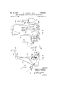
- FIG. 1 is a diagrammatic vertical elevation, partly in section, illustrating details of one embodiment of grinding mill with which a heating and air control system is employed which incorporates principles of the present invention.
- FIG. 2 is a diagrammatic vertical elevation, partly in ection, showing still another type of mill similar to that illustrated in FIG. 1 but employing different types of heating and air circulation means from that illustrated in FIG. 1.
- FIG. 3 is a diagrammatic vertical elevation, partly insection, showing a somewhat different type of grinding mill from that illustrated in FIGS. 1 and 2 and also embodying heating and reverse current air circulation means which are different from those employed in the embodis ments illustrated in FIGS. 1 and 2.
- FIG. 4 is a diagrammatic vertical elevation, partly in section, showing a still different type of mill with which a further type of heating and air circulation means is employed from those illustrated in the preceding figures.
- FIG. 5 is a diagrammatic vertical elevation, partly in section, and illustrating still another type of mill with which other types of heating and air circulation means are employed from those illustrated in t. e preceding fig ures and employing reverse currents.
- FIG. 6 is a diagrammatic vertical elevation, partly in section, and illustrating still another type of mill with which other types of heating and air circulation means are employed from those shown in the preceding figures.
- the mill is mounted for rotation on trunnions 12 at opposite ends thereof, said mill being of the autogenous grinding type, where the material to be ground actually grinds itself, said mill preferably having a diameter materially greater than the axial length of the grinding compartment of the mill.
- a chute feeder 14 extends upwardly and outwardly from the entrance end of 16 of the mill, to receive incoming material such as ore 18 from a feed conveyor 20. Some of the material 18 under normal circumstances will be very coarse, which makes it necessary to provide a relatively large feed opening 22 through the chute feeder 14.
- the present invention encompasses the use of a means and method of balancing the air pressure at the feed end of the mill so that it may be above, equal to, or below atmospheric, at the will of the operator.
- the system also comprises means for maintaining and controlling the air flow, when changes occur resulting from such variables among others as change in feed rate, feed size, moisture content, ambient temperature, humidity, and the like, which conditions when encountered heretofore have caused inefficient operation under a combination of variables unless elaborate precautions were taken to prevent air leakage at the feed end.
- the air classifying, conveying and drying circuit includes a unique method of introducing the hot gases under pressure, in the desired quantity and temperature as well as pressure, to balance or compensate for the moisture-laden gases exhausted from the system, details of which will be described hereinafter.
- the amount of vacuum required in accordance with the present invention is substantially zero compared to that which was necessary prior to the conception of placing the hot air generating system under pressure, usually above atmospheric pressure, and combining the same with the overall mill-air classifying circuit so as to form, in effect, a push-pull operation with the neutral point usually being at or closely adjacent the feed entrance to the mill which of necessity is composed of a relatively large area which is physically open to the atmosphere and through which solid material to be treated enters the mill and large volumes of air may be drawn in at very low differential in static pressure or suction heads.
- the system illustrated in FIG. 1 employs such push-pull principle which is produced by the following mechanism operated as described hereinafter.
- the air from the mill 10 is discharged through the exit 24 into a classifier compartment 26, in the lower portion of which the coarse product collects and is dropped from an air lock discharge 28, from which it is either reintroduced into the mill for further processing or if it is a finished product, suitable disposal thereof is made.
- the interior of the mill 10 is normally under a negative pressure by means to be described, and suction is maintained in the discharge riser conduit 30 which communicates with the product collector 32.
- the finer products carried by the air currents 34 which entrain the same and pass through the exit of the mill rise upwardly through the conduit 30 to the product collector 32.
- the fine product from the collector is discharged through an air lock 36. Suction is induced within the product collector 32 by a fan 38 which is driven from a suitable source of power.
- An air delivery conduit 40 communicates with the pressure side of the fan 38, there being a branch conduit 42 leading therefrom and having a control damper 44 therein, the branch conduit 42 discharging into a suitable collector 46 which may comprise a bag collector, for example, having an airlock discharge device 48 on the lower end thereof.
- the lower end of the air delivery conduit 40 communicates with the feed opening 22, into which air under pressure is delivered as a result of the operation of the fan 38.
- a pressure-type heater 50 is employed, which may be fired by any suitable and preferably economical type of fuel.
- the heater 50 receives air to be heated through a conduit 52, through which air is drawn by means of a blower 54, the conduit 52 being on the suction side thereof.
- Suitable control dampers 56 and 58 respectively are mounted in the air conduit 52 and the pressure conduit 69 from blower 54. Heated air is delivered under pressure from the pressure-type heater 50 through a preferably insulated conduit 62 which communicates with the air delivery conduit 40 adjacent the feed opening 22 as is clearly shown in FIG. 1, the conduit 62 also having a branch conduit 64 extending upwardly therefrom and communicating with branch conduit 42 from conduit 40. Branch conduit 64 preferably has a control damper 66 therein.
- a vent fan 68 communicates preferably with the upper end of collector 46 by means of a conduit 70 having a control damper 72 therein.
- the conduit 40 at a location past the branch conduit 42, also has a control damper 74 therein. Air circulating in the closed circuit system comprising the mill 10, conduit 30, product collector 32, and air delivery conduit 40, is controlled by the dampers 44 and 74.
- the hot air entering the system is controlled by damper 56 located ahead of the heater blower 54, and the vent air which carries off the moisture from the system is controlled by damper 72 on the suction side of vent fan 68.
- the fan 38 primarily is a circulating fan which nevertheless produces positive and negative pressures in various portions of the circuit and system, fan 54 creates positive pressure in the system and comprises the push portion of the push-pull efiect produced by the system, and fan 68 comprises the pull" portion to said push-pull effect of the system.
- the additional closed circuiting arrangement through fan 38 and conduit 40 is available to supplement the hot air entering from the outside.
- the quantity of circulating air may be regulated with relation to the quantity of fresh heated air introduced into the system so as to produce the desired quantity of circulating air and at the same time balance the system in accordance with the invention.
- the air entering the mill 10 is drawn therethrough by suction from the suction side of the fan 38 as well as the suction side of vent fan 68.
- the return air on the outlet or pressure side of fan 38 normally is above atmospheric pressure as is also the hot air from heater 50 in conduit 62 as a result of the action of blower 54. If, for example, the circulating air returning to the mill is regulated principally by operation of damper 74, but
- dampers 44- and/ or 72 which are in the same general line, so as to draw a substantial quantity of air out of the system through the vent fan 68, there will be a net overall suction effect on the feed opening 22, as a result of which cold air will be drawn in at said feed opening, with the resultant effect upon the temperature and volume of air circulating within the mill.
- the blower 5'4 raises the pressure in the heater outlet conduit 62 sufiiciently to balance out the otherwise negative pressure in the feed opening 22 as described above, thereby eliminating the introduction of cold air at the feeder.
- damper 56 sufi'iciently there can be produced an actual positively exerted pressure in the feed opening 22, resulting in a tendency to blow out air at this point but this is not considered desirable under normal operating conditions as this will tend to discharge some of the dusty air or gas fumes circulating in the system.
- the overall effect in the system can be that the circulating air therein which is caused primarily by the fan 38 practically can be independent of the amount of heated air introduced to the system as well as the moist air exhausted therefrom, with a positive control of the amount of air entering and leaving the system.
- the control of the total air circuit in the mill thus can be stabilized to a far greater degree than has been possible heretofore and, furthermore, the regulation of heated air under a far wider range of inlet temperatures than was possible.
- fresh air can be drawn in at the feed opening 22 when the system is regulated to permit the same, thereby diluting the heated air but under closely controlled conditions since the hot air is supplied likewise at closely controlled rates by means of separate blower 54 independently of what may be taking place in the rest of the circuit or system.
- the present invention contemplates effective means to accomplish this, whereby the desired quantity of hot air from the heater 56 may be by-passed through branch conduit 64 as controlled by damper 66 therein so as to raise the temperature of the exhausted air introduced into the collector 46 to prevent condensation therein or in the outlet conduits.
- the collector 46 is a bag collector, the extremely fine material on the bags will drop therefrom and be delivered in a dry flowable state to the discharge airlock 48.
- the draft gauge 76 can be connected electrically to an operators control panel 78 for control of any desired air pressure level either above or below atmospheric, with the sensing modulating control device, in turn, operating a motorized control linkage 80 which will operate the damper 56 to maintain the pressure at the preset amount desired.
- the moisture-laden air leaving the system also is controlled by suitable circuitry from control panel 78 and draft gauge 76 to a motorized modulating control linkage 32, whereby the damper 72 on.
- both means for damper control may be employed simultaneously or independently, through the samecontrol source.
- the mill 84 is mounted for rotation andis suitably driven by means, not shown, similar to the mill 10 in the embodiment shown in FIG. 1.
- a chute feeder 86 leads to the entrance of the mill and defines a feed opening 88.
- the pressure-type heater 90 has. an air conduit 92 provided with a control damper 94 and communicating with an air feed blower 96. The discharge end of the heater 90 communicates directly with the feed opening 88.
- the exit end of the mill 84 communicates with a classifier compartment 98, for example, having an airlock discharge 1490.
- the outlet conduit 162 of classifier compartment 98 communicates with the suction end of blower 104, the conduit 102 has a control damper 106 therein and the positive pressure end of blower 104 communicates with a discharge conduit 198 which may lead to a product collector, or otherwise.
- FIG. 2 does not specifically illustrate re-circulation of air, it embodies a push-pull arrangement, whereby the air delivered by the air feed blower 96 is controlled through damper 94 to a pressure-type heater 90 to comprise the push of the arrangement, while the suction blower 10.4 is controlled through damper 106 to comprise the pull thereof, whereby it is possible to balance the pressures or to operate the mill system so that, in the feed opening 88, any desired pressure head or suction head may be obtained, thus eliminating air leakage into the system through the feed opening 88 or to maintain a definite inlet rate of cold air at such inlet, as desired.
- an exemplary feed means comprising a conveyor 110 conveys material to the. grinding mill from a bin 112 which represents a source of supply.
- This embodiment of the invention also contemplates the use of an automatic control system comprising a draft gauge 114 which is similar in nature and function to the gauge 76 in the embodiment illustrated in FIG. 1.
- modulating controls such as motorized control linkage units 116 and 118 are each connected by suitable circuitry with the draft gauge 1 14, or an intermediate operators control panel, not shown in detail, but similar, for example, to the control panel 78 in the embodimentshown in FIG. 1.
- the modulating controls 116 and 118 respectively are connected by suitable linkage to the dampers 94 and 106, thereby to control the pressure and; suction of the push-pull arrangement of the system.
- the dampers 94 and 106 may be arranged so as to maintain either a constant pressure under varying conditions at the feed opening 88, or otherwise.
- this arrangement is one whereby there are two sources of gas or air proportioned in connection with a grinding mill and wherein, at the feed opening of the mill, by virtue of the system requiring a large open space, said feed opening is exposed to the atmosphere.
- FIGS. 3 comprise rotating mills of the tumbling type with which a pressure-type heater is associated and the principle of reverse-current circulation of air is employed.
- the product is discharged from the rotating mill 120 through a central conduit 122 substantially coaxial with the exit end of the mill and through which the product is conducted while entrained in an air current for movement to classifier unit 124.
- the oversize material from the classifier 124 is returned by gravity through conduit 126 to the entrance chute 128 of the mill, for further processing.
- the desired fine product is conveyed by air to a product collector 130 and from which the desired product is discharged through airlock 132.
- the air possibly containing a small amount of dust, returns to the blower 134.
- a vent pipe 136 extends upwardly from the pressure side of the blower 134, ahead of the regulating damper 138, and controls the introduction of air from blower 134 through air conduit 140 which surrounds the entrance end of central conduit 122 and communicates with the exit end of the mill 120, all as clearly shown in FIG. 3.
- the vent pipe 136 also contains a control damper 142 by which the air to be vented is regulated.
- dampers 138 and 142 can be balanced through the regulation of dampers 138 and 142, whereby essentially no air is drawn in at the entrance 128 of the mill, under conditions where the introduction of hot air is not needed for drying material, but if and when hot air is needed, regulation of damper 150 for admission of hot air and readjustment of dampers 138 and 142 will permit the introduction of the heated air in the amount desired with or without the infiltration of cold air at the entrance 128.
- blower 134 in order to force the vent air from the feed end of the mill to discharge through the vent pipe 136 and thereby cause a sufficient amount of suction in the entrance chute 128 to draw in heated air from a heater. Heated air could be introduced in reasonable quantities but was greatly diluted with cold air unless an effective airlock-type feeder was employed.
- an exemplary bin 151 discharges raw material onto a suitable feed belt for introduction to the entrance chute 128, similarly as in the feed arrangement shown in the embodiment illustrated in FIG. 2. It also will be seen relative to the embodiment shown in FIG. 3 that the blower 146 comprises the push part of the push-pull arrangement of said embodiment, while the blower 134, which is connected at its suction end to conduit 152 leading from product collector produces a suction in central conduit 122 which serves as the pull portion of the push-pull arrangement of the system.
- FIG. 4 Still another embodiment of the invention using a tumbling type mill is illustrated in FIG. 4, wherein the mill 154 is mounted for rotation about its axis.
- the operation is such that the mill 154 need not be subjected to large amounts of air for circulation within the mill itself and classification of the products, or where the amount of hot air for drying need not be required for conveying or classifying purposes.
- the velocity of air through the mill can be at a relatively low rate unless operation calls for an air-sweeping action.
- Such relatively low velocity of air through the mill is desirable under certain conditions, such as where it is advantageous to maintain a large quantity of fine material intermixed with the grinding media.
- the mill under the foregoing circumstances, may be made more or less independent of the classifying system, if desired.
- heated air can be supplied in relatively small quantities, under relatively high temperature conditions, and where the pressure required to introduce the hot air may be relatively high as, for example, where a screw feeder is employed such as feed screw 156 in the present embodiment.
- a balanced system between the main classifier fan 158 and the blower 160 for the heater 162 can be maintained.
- vent damper 164 If a vent fan is used, suitable controls for the various dampers and particularly the vent damper 164 can be employed so that the overall net result is a maintenance of zero pressure drop or whatever other pressure is desired, at either the feed end of the mill or even at the discharge end of the mill if desired.
- the various illustrated but non-described product collectors, classifiers, and similar devices shown in FIG. 4 are intended primarily to be exemplary, the same being somewhat similar to corresponding elements in the embodiment shown in FIG. 3. Accordingly, attention is directed to such figure for these details.
- FIG. 5 still another embodiment of the invention which is somewhat similar to that shown in FIG. 3 and principally is adapted for use in grinding coal or conveying a product pneumatically a considerable distance from the grinding source before collection or use in a further process.
- a balancing principle is employed in this embodiment so as to permit the use of an open feeder.
- This embodiment departs from similar practice wherein a closed type of feeder has been re quired, especially when heated air has been considered necessary for use to assist in drying the material during grinding operations.
- the blower 164 introduces air under pressure into the pressure-type heater 166.
- the heated air from the outlet end of the heater is distributed between two conduits 168 and 170, each having its own regulating damper 169 and 171, respectively, as clearly shown in FIG. 5.
- Conduit 170 communicates with the feed end of mill 172 and a chute feeder 174 also communicating with said entrance end.
- Conduit 168 communicates with the exit end of the mill, whereby heated air enters the mill from both the feed and discharge ends thereof.
- the supply of heated air at the feed end tends to dry the material being fed to the mill directly at the feed point, while the material at the discharge end is subjected to a blowing action of heated air which blows the oversize material back into the mill and also further dries the partially ground product which is located near the discharge end.
- any oversize material dropping back from the classifier 173 is discharged back into stationary hood 182 and from whence it is elevated by suitable lifter means rotating with the mill and returned to the interior of the mill by being deposited on cone 18% which deflects it back into the mill past the grate 176 and as the material falls from said cone in front of the incoming hot air from conduit 158, said coarser particles of material are blown back into the mill, while the fine product which leaves the classifier 173 may be considered sufficiently line that no further treatment is necessary or it may require finer classification.
- the blower 164 comprises the push portion of the push-pull arrangement of the system, while the exhaust fan 188 comprises the pull portion of said arrangement in the system.
- the intake blower 164 as controlled by the damper 192 in the inlet conduit thereto, in coordination with the damper 190 controlling the supply to suction exhaust fan 188.
- Such regulation may be accompanied by suitable regulation of the dampers shown respectively in conduits 16S and 170 to control the air inlet at the feed and discharge ends of the mill.
- the food may be furnished from an exemplary bin 194 which discharges onto a suitable feed conveyor 196.
- a roller-type of mill as distinguished from a tumblingtype is illustrated in the embodiment shown in FIG. 6.
- the same basic push-pull principle can be applied to this type of mill as Well as the other types incorporated in the various embodiments described hereinaoove and illustrated in the preceding figures.
- the circulating system for the interior of the mill 1% comprises a fan 2%, the pressure end of which is divided between two conduits 2M and 204 which respectively have control dampers therein, the conduits 252 communicating directly with the lower portion of the mill 1% so as to direct a positive current of air from the lower portron to the upper portion thereof for purposes of entraining the finer products produced by the mill for removal therefrom.
- the inlet end of the fan 2% communicates with a product collector 236 by means of suc tion conduit 21% which communicates with the upper end of mill 193.
- Said mill employs rollers 212 of a wellknown type for purposes of crushing material within the mill.
- the system is similar to that illustrated in the embodiment shown in FIG.
- the control damper 230 in pressure conduit 202 controls the main circulating air stream through the mill 1% and, as in regard to the embodiment shown in FIG. I, balancing within the mill circuit itself may be accomplished by controlling the damper 228 ahead of the heater blower 224. This controls the inlet air, while the control of the exhaust vent air is accomplished by adjusting the damper 21% ahead of the suction vent fan 214.
- the system is such that the circulating air supply may be controlled and the heated air supply may also be controlled together with the moisture-laden vent air supply.
- auxiliary air or other gas from the outside in controlled amounts is desired in order that such air or other gas, without being heated, may be sufiiciently low in humidity to aid in the drying action without necessitating the use of additional heat or such auxiliary air may be desired as a conveyor or the powdered material, or for any other purposes such as, for instance, the introduction of a neutral gas when grinding a material subject to possible explosion. Under such circumstances, the push-pull arrangement described hereinabove nevertheless is employed.
- a mill system for grinding mineral material comprising in combination, a mill having a feed opening physically open to the atmosphere and substantially unrestricted to the simultaneous delivery thereto of solid material and elastic fluid, said mill also having exit means through which solid material and elastic fluid are discharged from said mill following the operation of said mill upon said solid material, means to deliver solid material to the feed opening of said mill for treatment within said mill, means for treating elastic fluid and delivering it to said feed opening, means to control the pressure of said elastic fluid treated for delivery to said feed opening, and additional pressure control means operable to regulate the pressure of the elastic fluid discharged from the exit of said mill, whereby said pressure control means may be regulated relative to each other to provide at the feed opening of said mill an elastic fluid pressure of predetermined amount and thereby control the amount of atmospheric air introduced into said mill through said feed opening.
- the mill system set forth in claim 1 further including means to recirculate at least a portion of the elastic fluid withdrawn from the exit means to the feed opening of said mill and means to control the amount of elastic fluid thus recirculated, whereby said control means may be regulated relative to the aforementioned control means to control the amount of atmospheric air introduced into said mill through said feed opening.
- a system for grinding solid material comprising in combination, a mill having a feed entrance open physically to the atmosphere and through which raw material is introduced into the mill, said mill also having exit means through which material is removed from the mill, means operable to cause a stream of elastic fluid to flow through said mill, adjustable means operable to introduce an independent stream of elastic fluid into said mill through said feed entrance at a predetermined pressure to provide an atmosphere therein of a desired character for grinding operations, and adjustable flow control means operable to withdraw said atmosphere from said m ll to produce a pressure therein less than said predetermined pressure of said elastic fluid fed to said feed entrance and regulated to control the flow of said elastic fluid into said mill through said feed entrance.
- a system for grinding solid material comprising in combination, a mill having a feed entrance physically open to the atmosphere and through which raw material is introduced into the mill, said mill also having exit means through which material is removed from the mill, means operable to cause a stream of elastic fluid to flow through said mill, means to heat desired elastic fluid to a predetermined temperature, adjustable means operable to introduce an independent stream of said heated elastic fluid into said mll through said feed entrance substantially continuously in controlled predetermined amounts to provide an atmosphere therein of a desired character for grinding operations different from the exterior atmosphere, and adjustable flow control means operable to produce a regulated pressure within said mill adjacent the exit means less than the pressure of the heated elastic fluid introduced to said mill to effect withdrawal of elastic fluid from said exit and thereby control the flow of said elastic fluid into said mill.
- a mill system for grinding mineral material comprising in combination, a mill having a feed entrance physically open to the atmosphere to receive raw material, said mill also having exit means through which material is removed from the mill, means to heat desired elastic fluid to a predetermined temperature, adjustable means operable to introduce said heated elastic fluid into said mill through said feed entrance substantially continuously at a predetermined pressure and temperature to provide an atmosphere therein of a desired character for grinding operations different from the exterior atmosphere, adjustable suction means operable to produce a regulated pressure at the exit of said mill less than the pressure at the feed entrance, thereby eflecting withdrawal of the internal atmosphere from said mill through the exit thereof at a rate regulated to maintain the pressure of the elastic fluid fed into the feed entrance of said mill at a desired amount relative to exterior atmospheric pressure to control the inlet of exterior atmospheric air through said feed entrance as desired, and control means including a draft gauge positioned adjacent said open feed entrance and responsive to the pressure in said feed entrance and operable to regulate the pressure of the elastic fluid withdrawn from said exit of said mill relative to the elastic heated fluid introduced to said mill to provide
- a system for grinding solid material comprising in combination, a mill having a feed entrance physically open to the atmosphere and through which raw material is introduced into the mill, said mill also having exit means through which material is removed from the mill, means to heat desired fresh elastic fluid to a predetermined temperature independently of the mill atmosphere, conduit means extending from said heating means and directed into the open entrance of said mill, adjustable flow control means operable relative to said conduit means operable to introduce said heated fresh elastic fluid into said mill substantially continuously in predetermined amounts to provide an atmosphere therein of a desired character for grinding operations different from the exterior atmosphere, adjustable means operable to produce a regulated predetermined pressure adjacent the exit means less than that at the entrance of said mill to effect Withdrawal of elastic fluid from said mill through said exit and thereby control the feed of said heated fresh elastic fluid into said mill at a desired pressure to control the movement of exterior atmospheric air into the mill through said feed entrance, a by-pass conduit extending between said conduit means and said adjustable means to effect said withdrawal of elastic fluid from said heating means, and adjustable flow control means in said by-pass conduit operable to
- a system for grinding solid material comprising in combination, a mill having a feed entrance physically open to the atmosphere and through which raw material is introduced into the mill, said mill also having exit cans through which material is removed from the mill, adjustable means operable to introduce elastic fluid into said mill through said entrance at a predetermined pressure to provide an atmosphere therein of a desired character for grinding operations different from the exterior atmosphere, additional adjustable means operable to introduce elastic fluid at a desired pressure into the exit of said mill and at least partially flowing counter-current to the fluid flowing through the entrance to said mill and operable to entrain fine produce material Within said mill, and adjustable means operable to produce a negative pressure regulated to effect withdrawal of elastic fluid and entrained product material through the exit of said mill and thereby control the feed of said elastic fluid into said mill at a desired pressure to regulate the inlet of atmospheric air through said teed entrance as desired.
- a system for grinding solid material comprising in combination, a mill having a feed entrance physically open to the atmosphere and through which raw material is introduced into the mill, said mill also having an exit through which material is removed from the mill, means to heat desired elastic fluid to a predetermined temperature, conduit means connected to said entrance and exit of said mill and operable to direct said heated elastic fluid from said heating means into said mill substantially continuously in predetermined amounts through both said entrance and exit to entrain fine product material therein while traveling counter-current to each other and thereby provide an atmosphere therein of a desired character for grinding operations different from the exterior atmosphere, adjustable flow-control means in said conduit means respectively connected to said entrance and exit, and adjustable means interconnected to the exit of said mill and operable to produce a regulated pressure adjacent the exit means less than that at the entrance of said mill to effect withdrawal of elastic fluid and entrained fine material from said exit and thereby effect the feed of said elastic fluid into said mill at a desired pressure to control the pressure of elastic fluid at said entrance and thereby regulate the movement of exterior atmospheric air through said feed entrance as desired.
- the method set forth in claim 13 further including the step of regulating the pressure of the returned elastic fluid relative to the pressure of the treated elastic fluid introduced into the unprotected entrance of said mill to produce a desired pressure at the unprotected feed entrance of said mill to control the entrance therethrough of untreated surrounding atmospheric elastic fluid.
Landscapes
- Engineering & Computer Science (AREA)
- Food Science & Technology (AREA)
- Crushing And Grinding (AREA)
- Disintegrating Or Milling (AREA)
Description
Feb. 19, 1963 R. J. RUSSELL ETAL MEANS AND METHODS OF SUPPLYING HEAT TO GRINDING MILLS Filed Nov. 12, 1959 s Sheets-Sheet 1 INVENTORJ 205527- J, 203.554; HAELOWE' HQED/MGE ATTORNEY Feb. 19, 1963 R. J. RUSSELL ETAL 3,078,048
MEANS AND METHODS OF SUPPLYING HEAT TO GRINDING MILLS Filed Nov. 12, 1959 5 Sheets-Sheet 3 ATTORNEY Patented Feb. 19, 1 963 MEANS AND METHGDS @F SUPPLYHNG HEAT T GRENDENG MlLLS Robert J. Russell and Harlowe Hardinge, York, Pa, assignors to Hardinge (Zompany, Inc., York, ha, a corporation of New York Filed Nov. 12, 1959, Eler. No. 852,5tl'7 14- Clairns. (Cl. 241-17) The present invention relates to a plurality of different embodiments of means and methods of supplying heat to grinding mills, and more particularly to grinding mills and systems which require a relatively large opening to introduce the feed thereto and where the feed sizes are above average, especially when applied to autogenous grinding mills wherein so-called run-of-the-mine size feeds are introduced to the mill.
Heretofore, the feeding of material to be ground to grinding mills and particularly autogenous grinding mills has introduced serious problems in regard to attempting to avoid or minimize the introduction of unwanted cold air at the feed entrance of the mill. Where the amount of material to be ground is relatively large with relation to the size of the grinding mill and the heated air requirements are appreciable to dry the material during the grinding operation, high inlet temperatures are usually necessary. Heretofore, a system of this nature introduced the heated air by drawing in the hot air under suction at the feed end. Unless a suitable airlock system was provided, tov exclude cold air from entering the space provided for the material being fed, a considerable quantity of cold air would also enter the mill. This is objectionable, as it increases the overall air requirements and velocities in the system. When large feed sizes are encountered, this practice entails serious consequences, since providing suitable airlocks for coarse feeds is bulky, cumbersome and costly.
It is well known in the art of so-called dry grinding that capacity is increased with an increase in dryness of the material. Some materials, such as coal, can be ground in the so-called dry state with but minor effect on capacity when the surface moisture in the material is in the order of 3 to 5%, for example. Other materials, however, such as some types of limestone, if exceeding 1% in surface moisture will tend to pack in the mill and grinding will cease entirely unless the moisture is removed and reduced in some cases in the order of 0.25%. As a still further example, in regard to handling material such as iron ore which is heavy, and where the product need not be exceedingly fine, capacity for a given size of mill is relatively high but so also is the Weight of water in the ore which must be evaporated before and during the grinding operation to obtain satisfactory results from the grinding system.
The principal object of the present invention is to obviate the difiiculties referred to hcreinabove by providing means to supply heat to grinding mills in a manner to permit a greater degree of flexiblity of operation of the mill, eliminate or minimize and control the introduction of cold or auxiliary air at the inlet or feed end of the mill, and enable the overall mill operation to be controlled in a simpler and more stable manner than has been possible heretofore.
Another object of the invention is to provide heating and drying mechanism which will remove moisture from damp material efliciently as it is being ground so as to improve the efficiency of the grinding operation.
A further object of the invention is to supply heat to a mill at higher temperatures than has heretofore been possible without injury to the apparatus, thereby to ob t-ain more efiicient operation and use less, air in. the mill system, with attendant lower velocity and maintenance costs than has been possible heretofore.
Still another object of the invention is to provide a heating system for mills requiring less overall power to operate the same than heretofore, such heating means employing an air system which requires less power to operate as a result of better application of the power and handling of hot air in the system, as Well as better handling of the total air in the grinding circuit and system and in the exhaust or duct-filter system, since each component or section of the circuit or system may be supplied with its own means controlling the handling of air in each component or section to the best advantage for the overall system.
A still further object of the invention is to provide a plurality of embodiments of heating systems for grinding mills of diiferent types in which the control and handlingof heated air within the mill system is accomplished efficiently by durable and relatively simple apparatus capable of achieving the objectives set forth hereinabove, the specific arrangement of heating system and air controland circulating arrangement for each individual mill being such as to produce maximum efficiency for a particulartype of mill with which it is associated in accordance with the individual disclosuresset forth hereinafter and illustrated in the accompanying drawings.
In the drawings:
FIG. 1 is a diagrammatic vertical elevation, partly in section, illustrating details of one embodiment of grinding mill with which a heating and air control system is employed which incorporates principles of the present invention.
FIG. 2 is a diagrammatic vertical elevation, partly in ection, showing still another type of mill similar to that illustrated in FIG. 1 but employing different types of heating and air circulation means from that illustrated in FIG. 1.
FIG. 3 is a diagrammatic vertical elevation, partly insection, showing a somewhat different type of grinding mill from that illustrated in FIGS. 1 and 2 and also embodying heating and reverse current air circulation means which are different from those employed in the embodis ments illustrated in FIGS. 1 and 2.
FIG. 4 is a diagrammatic vertical elevation, partly in section, showing a still different type of mill with which a further type of heating and air circulation means is employed from those illustrated in the preceding figures.
FIG. 5 is a diagrammatic vertical elevation, partly in section, and illustrating still another type of mill with which other types of heating and air circulation means are employed from those illustrated in t. e preceding fig ures and employing reverse currents.
FIG. 6 is a diagrammatic vertical elevation, partly in section, and illustrating still another type of mill with which other types of heating and air circulation means are employed from those shown in the preceding figures.
Although a number of different embodiments of mills, heating systems, and air circulation means are illustrated. in the various figures ofthe drawings, it will be seen. that, in general, certain basic principles: are incorporated in all of said various embodiments in accordance with the principles of the present invention. Although the various embodiments illustrated in the drawings and described hereinafter employ similar basic principles of the invention, it is to be understood that said embodiments are not equivalents of each other since the same have different operational characteristics and details which are not identical, whereby the different embodiments are intended to have maximum efiiciency in association with the particular mills and arrangements with which they are com-; bined as described hereinafter.
Referring to the first embodiment which is illustrated principally in FIG. 1, the mill is mounted for rotation on trunnions 12 at opposite ends thereof, said mill being of the autogenous grinding type, where the material to be ground actually grinds itself, said mill preferably having a diameter materially greater than the axial length of the grinding compartment of the mill. A chute feeder 14 extends upwardly and outwardly from the entrance end of 16 of the mill, to receive incoming material such as ore 18 from a feed conveyor 20. Some of the material 18 under normal circumstances will be very coarse, which makes it necessary to provide a relatively large feed opening 22 through the chute feeder 14.
Unless provision is made in some manner to prevent the entrance of outside cold air through the feed opening 22, the overall efficiency of the operation of the mill and system would be considerably reduced. However, in accordance with the principles of the present invention, rather than use a bulky, cumbersome, and costly air lock system or the like, reference to which has been made hereinabove, the present invention encompasses the use of a means and method of balancing the air pressure at the feed end of the mill so that it may be above, equal to, or below atmospheric, at the will of the operator. Furthermore, the system also comprises means for maintaining and controlling the air flow, when changes occur resulting from such variables among others as change in feed rate, feed size, moisture content, ambient temperature, humidity, and the like, which conditions when encountered heretofore have caused inefficient operation under a combination of variables unless elaborate precautions were taken to prevent air leakage at the feed end. In the instant invention, the air classifying, conveying and drying circuit includes a unique method of introducing the hot gases under pressure, in the desired quantity and temperature as well as pressure, to balance or compensate for the moisture-laden gases exhausted from the system, details of which will be described hereinafter.
In operating grinding systems of this nature hereinbefore, it has been the usual practice to introduce the hot gases by means of placing the milling and classifying system under a partial vacuum and thus cause a suction effect on the hot air heater to draw in the hot gases necessary to dry the material undergoing reduction. The net result is that cold air was also caused to be drawn in from the outside to enter any point which was connected with the outside, whether at the feed end or at other points in the system such, for example, as at the product outlet where an air gap between the rotating joints of the stationary and moving portions of the mill may be appreciable.
The amount of vacuum required in accordance with the present invention is substantially zero compared to that which was necessary prior to the conception of placing the hot air generating system under pressure, usually above atmospheric pressure, and combining the same with the overall mill-air classifying circuit so as to form, in effect, a push-pull operation with the neutral point usually being at or closely adjacent the feed entrance to the mill which of necessity is composed of a relatively large area which is physically open to the atmosphere and through which solid material to be treated enters the mill and large volumes of air may be drawn in at very low differential in static pressure or suction heads. The system illustrated in FIG. 1 employs such push-pull principle which is produced by the following mechanism operated as described hereinafter.
The air from the mill 10 is discharged through the exit 24 into a classifier compartment 26, in the lower portion of which the coarse product collects and is dropped from an air lock discharge 28, from which it is either reintroduced into the mill for further processing or if it is a finished product, suitable disposal thereof is made. The interior of the mill 10 is normally under a negative pressure by means to be described, and suction is maintained in the discharge riser conduit 30 which communicates with the product collector 32. The finer products carried by the air currents 34 which entrain the same and pass through the exit of the mill rise upwardly through the conduit 30 to the product collector 32. The fine product from the collector is discharged through an air lock 36. Suction is induced within the product collector 32 by a fan 38 which is driven from a suitable source of power.
An air delivery conduit 40 communicates with the pressure side of the fan 38, there being a branch conduit 42 leading therefrom and having a control damper 44 therein, the branch conduit 42 discharging into a suitable collector 46 which may comprise a bag collector, for example, having an airlock discharge device 48 on the lower end thereof. The lower end of the air delivery conduit 40 communicates with the feed opening 22, into which air under pressure is delivered as a result of the operation of the fan 38. At a suitable location ahead of the feed opening 22, hot air is introduced therelnto by suitable means. In accordance with the present embodiment of the invention, a pressure-type heater 50 is employed, which may be fired by any suitable and preferably economical type of fuel. The heater 50 receives air to be heated through a conduit 52, through which air is drawn by means of a blower 54, the conduit 52 being on the suction side thereof.
A vent fan 68 communicates preferably with the upper end of collector 46 by means of a conduit 70 having a control damper 72 therein. The conduit 40, at a location past the branch conduit 42, also has a control damper 74 therein. Air circulating in the closed circuit system comprising the mill 10, conduit 30, product collector 32, and air delivery conduit 40, is controlled by the dampers 44 and 74. The hot air entering the system is controlled by damper 56 located ahead of the heater blower 54, and the vent air which carries off the moisture from the system is controlled by damper 72 on the suction side of vent fan 68. In effect therefore, the fan 38 primarily is a circulating fan which nevertheless produces positive and negative pressures in various portions of the circuit and system, fan 54 creates positive pressure in the system and comprises the push portion of the push-pull efiect produced by the system, and fan 68 comprises the pull" portion to said push-pull effect of the system.
Assuming, for example, in the circuit illustrated and described relative to FIG. 1 that more air is required in the mill to remove the product and classify it than could be supplied by the air from the heater alone, the additional closed circuiting arrangement through fan 38 and conduit 40 is available to supplement the hot air entering from the outside. By adjustment of the various dampers described, the quantity of circulating air may be regulated with relation to the quantity of fresh heated air introduced into the system so as to produce the desired quantity of circulating air and at the same time balance the system in accordance With the invention.
The air entering the mill 10 is drawn therethrough by suction from the suction side of the fan 38 as well as the suction side of vent fan 68. However, the return air on the outlet or pressure side of fan 38 normally is above atmospheric pressure as is also the hot air from heater 50 in conduit 62 as a result of the action of blower 54. If, for example, the circulating air returning to the mill is regulated principally by operation of damper 74, but
also partially by regulating dampers 44- and/ or 72 which are in the same general line, so as to draw a substantial quantity of air out of the system through the vent fan 68, there will be a net overall suction effect on the feed opening 22, as a result of which cold air will be drawn in at said feed opening, with the resultant effect upon the temperature and volume of air circulating within the mill.
In lieu of the adjustment and regulation described in the paragraph immediately above, if the damper 56 is regulated to control the air entering the blower 54 for introduction into the heater 59, the blower 5'4 raises the pressure in the heater outlet conduit 62 sufiiciently to balance out the otherwise negative pressure in the feed opening 22 as described above, thereby eliminating the introduction of cold air at the feeder. Moreover, by opening damper 56 sufi'iciently, there can be produced an actual positively exerted pressure in the feed opening 22, resulting in a tendency to blow out air at this point but this is not considered desirable under normal operating conditions as this will tend to discharge some of the dusty air or gas fumes circulating in the system. It thus will be seen that, especially when no cold outside atmospheric air is desired in the mill system and although the feed opening 22 is physically open to the atmosphere at all times in that the opening can be seen through from the exterior thereof, for example, said opening nevertheless is not actually open to the atmosphere in that atmospheric air can not enter the opening under such circumstances.
From the foregoing, it will be seen that the overall effect in the system can be that the circulating air therein which is caused primarily by the fan 38 practically can be independent of the amount of heated air introduced to the system as well as the moist air exhausted therefrom, with a positive control of the amount of air entering and leaving the system. The control of the total air circuit in the mill, under varying conditions, thus can be stabilized to a far greater degree than has been possible heretofore and, furthermore, the regulation of heated air under a far wider range of inlet temperatures than was possible.
previously, can be insured.
When it is desired to operate a heater at considerably higher than normal temperatures, especially to increase the heating efiiciency, fresh air can be drawn in at the feed opening 22 when the system is regulated to permit the same, thereby diluting the heated air but under closely controlled conditions since the hot air is supplied likewise at closely controlled rates by means of separate blower 54 independently of what may be taking place in the rest of the circuit or system.
Under conditions where high moisture content and large quantities of moisture-laden air which is near the saturation point are discharged, it is preferable to raise the temperature of the vent gases to avoid possible condensation on the vent conduits or on the collector surfaces, such as when filter cloth is employed to remove the dust. The present invention contemplates effective means to accomplish this, whereby the desired quantity of hot air from the heater 56 may be by-passed through branch conduit 64 as controlled by damper 66 therein so as to raise the temperature of the exhausted air introduced into the collector 46 to prevent condensation therein or in the outlet conduits. Under conditions where the collector 46 is a bag collector, the extremely fine material on the bags will drop therefrom and be delivered in a dry flowable state to the discharge airlock 48.
While the system described above will maintain the pressure at the feed opening 22 very close to the desired amount within a wide range of operating conditions, a further improvement may be used to insure stabilization under those conditions where more or less rapid changes occur that can not readily be compensated for by manual means within the time required for best results. Such stabilization can be obtained automatically to control the pressure ditferenial at any point such as, for example, directly at the feed opening 22, by using a draft gauge 76 which is mounted directly in the feeder opening and is electrically connected through a modulation control system to actuate the auxiliary circulating air in the system by varying the amount of air entering the heater, for example.
Details of the electrical control components of the modulation control system are not described since the same do not comprise a part of the present invention. However, the draft gauge 76 can be connected electrically to an operators control panel 78 for control of any desired air pressure level either above or below atmospheric, with the sensing modulating control device, in turn, operating a motorized control linkage 80 which will operate the damper 56 to maintain the pressure at the preset amount desired. Similarly, the moisture-laden air leaving the system also is controlled by suitable circuitry from control panel 78 and draft gauge 76 to a motorized modulating control linkage 32, whereby the damper 72 on.
the suction side of the vent fan 68 can be controlled. If desired, both means for damper control may be employed simultaneously or independently, through the samecontrol source.
In the embodiment illustrated in FIG. 2, the mill 84 is mounted for rotation andis suitably driven by means, not shown, similar to the mill 10 in the embodiment shown in FIG. 1. A chute feeder 86 leads to the entrance of the mill and defines a feed opening 88. In this embodiment, the pressure-type heater 90 has. an air conduit 92 provided with a control damper 94 and communicating with an air feed blower 96. The discharge end of the heater 90 communicates directly with the feed opening 88.
The exit end of the mill 84 communicates with a classifier compartment 98, for example, having an airlock discharge 1490. The outlet conduit 162 of classifier compartment 98 communicates with the suction end of blower 104, the conduit 102 has a control damper 106 therein and the positive pressure end of blower 104 communicates with a discharge conduit 198 which may lead to a product collector, or otherwise.
Although the embodiment illustrated in FIG. 2 does not specifically illustrate re-circulation of air, it embodies a push-pull arrangement, whereby the air delivered by the air feed blower 96 is controlled through damper 94 to a pressure-type heater 90 to comprise the push of the arrangement, while the suction blower 10.4 is controlled through damper 106 to comprise the pull thereof, whereby it is possible to balance the pressures or to operate the mill system so that, in the feed opening 88, any desired pressure head or suction head may be obtained, thus eliminating air leakage into the system through the feed opening 88 or to maintain a definite inlet rate of cold air at such inlet, as desired.
It may be desired at times to have the heater operate at temperatures higher than would be feasible if the heated air products are introduced directly into the mill. Accordingly, the same may be admixed with a quantity of outside or secondary air at the feed opening 83, which will result in tempering the heat in order that the overall delivery of heat to the mill will be at a satisfactory level. In this embodiment, an exemplary feed means comprising a conveyor 110 conveys material to the. grinding mill from a bin 112 which represents a source of supply.
This embodiment of the invention also contemplates the use of an automatic control system comprising a draft gauge 114 which is similar in nature and function to the gauge 76 in the embodiment illustrated in FIG. 1. Accordingly, modulating controls such as motorized control linkage units 116 and 118 are each connected by suitable circuitry with the draft gauge 1 14, or an intermediate operators control panel, not shown in detail, but similar, for example, to the control panel 78 in the embodimentshown in FIG. 1. The modulating controls 116 and 118 respectively are connected by suitable linkage to the dampers 94 and 106, thereby to control the pressure and; suction of the push-pull arrangement of the system.
By such control arrangement, the dampers 94 and 106 may be arranged so as to maintain either a constant pressure under varying conditions at the feed opening 88, or otherwise.
It will be seen that this arrangement is one whereby there are two sources of gas or air proportioned in connection with a grinding mill and wherein, at the feed opening of the mill, by virtue of the system requiring a large open space, said feed opening is exposed to the atmosphere. However, it is desired, for example, to provide a positive control of the pressure in said feed opening to provide usually an amount only sufiicient to prevent any positive pressure being exerted which would tend to contaminate the outside atmosphere with dust or obnoxious gases from the heater or both.
The embodiments illustrated in FIGS. 3 and comprise rotating mills of the tumbling type with which a pressure-type heater is associated and the principle of reverse-current circulation of air is employed. In the embodiment of FIG. 3, the product is discharged from the rotating mill 120 through a central conduit 122 substantially coaxial with the exit end of the mill and through which the product is conducted while entrained in an air current for movement to classifier unit 124. The oversize material from the classifier 124 is returned by gravity through conduit 126 to the entrance chute 128 of the mill, for further processing. The desired fine product is conveyed by air to a product collector 130 and from which the desired product is discharged through airlock 132. The air, possibly containing a small amount of dust, returns to the blower 134.
A vent pipe 136 extends upwardly from the pressure side of the blower 134, ahead of the regulating damper 138, and controls the introduction of air from blower 134 through air conduit 140 which surrounds the entrance end of central conduit 122 and communicates with the exit end of the mill 120, all as clearly shown in FIG. 3. The vent pipe 136 also contains a control damper 142 by which the air to be vented is regulated. The system illustrated in FIG. 3 can be balanced through the regulation of dampers 138 and 142, whereby essentially no air is drawn in at the entrance 128 of the mill, under conditions where the introduction of hot air is not needed for drying material, but if and when hot air is needed, regulation of damper 150 for admission of hot air and readjustment of dampers 138 and 142 will permit the introduction of the heated air in the amount desired with or without the infiltration of cold air at the entrance 128.
Under circumstances in the embodiment shown in FIG. 3 wherein hot air is needed, heretofore an unusual amount of pressure drop and loss was necessary at blower 134 in order to force the vent air from the feed end of the mill to discharge through the vent pipe 136 and thereby cause a sufficient amount of suction in the entrance chute 128 to draw in heated air from a heater. Heated air could be introduced in reasonable quantities but was greatly diluted with cold air unless an effective airlock-type feeder was employed. By using a pressure-type heater 144 as in the present invention however, particularly as aided by a blower 146 which draws air through inlet 148 to the heater as controlled by damper 150, it is possible by means of the present invention to introduce heat at the feed point under a positive pressure, with the result that the demand on blower 134 and the high pressure drop formerly required thereof can be greatly reduced with virtually entire elimination of cold air also being drawn in at the same time. Such an arrangement also results in the overall system being balanced to better advantage than was possible heretofore.
It will be seen that an exemplary bin 151 discharges raw material onto a suitable feed belt for introduction to the entrance chute 128, similarly as in the feed arrangement shown in the embodiment illustrated in FIG. 2. It also will be seen relative to the embodiment shown in FIG. 3 that the blower 146 comprises the push part of the push-pull arrangement of said embodiment, while the blower 134, which is connected at its suction end to conduit 152 leading from product collector produces a suction in central conduit 122 which serves as the pull portion of the push-pull arrangement of the system.
Still another embodiment of the invention using a tumbling type mill is illustrated in FIG. 4, wherein the mill 154 is mounted for rotation about its axis. In this embodiment, the operation is such that the mill 154 need not be subjected to large amounts of air for circulation within the mill itself and classification of the products, or where the amount of hot air for drying need not be required for conveying or classifying purposes. Hence, the velocity of air through the mill can be at a relatively low rate unless operation calls for an air-sweeping action. Such relatively low velocity of air through the mill is desirable under certain conditions, such as where it is advantageous to maintain a large quantity of fine material intermixed with the grinding media.
The mill, under the foregoing circumstances, may be made more or less independent of the classifying system, if desired. However, if material is to be dried during the grinding process, heated air can be supplied in relatively small quantities, under relatively high temperature conditions, and where the pressure required to introduce the hot air may be relatively high as, for example, where a screw feeder is employed such as feed screw 156 in the present embodiment. Nevertheless, in this embodiment, a balanced system between the main classifier fan 158 and the blower 160 for the heater 162 can be maintained. If a vent fan is used, suitable controls for the various dampers and particularly the vent damper 164 can be employed so that the overall net result is a maintenance of zero pressure drop or whatever other pressure is desired, at either the feed end of the mill or even at the discharge end of the mill if desired. The various illustrated but non-described product collectors, classifiers, and similar devices shown in FIG. 4 are intended primarily to be exemplary, the same being somewhat similar to corresponding elements in the embodiment shown in FIG. 3. Accordingly, attention is directed to such figure for these details.
There is illustrated in FIG. 5 still another embodiment of the invention which is somewhat similar to that shown in FIG. 3 and principally is adapted for use in grinding coal or conveying a product pneumatically a considerable distance from the grinding source before collection or use in a further process. However, a balancing principle is employed in this embodiment so as to permit the use of an open feeder. This embodiment departs from similar practice wherein a closed type of feeder has been re quired, especially when heated air has been considered necessary for use to assist in drying the material during grinding operations.
Referring to the details of FIG. 5, it will be seen that the blower 164 introduces air under pressure into the pressure-type heater 166. The heated air from the outlet end of the heater is distributed between two conduits 168 and 170, each having its own regulating damper 169 and 171, respectively, as clearly shown in FIG. 5. Conduit 170 communicates with the feed end of mill 172 and a chute feeder 174 also communicating with said entrance end. Conduit 168 communicates with the exit end of the mill, whereby heated air enters the mill from both the feed and discharge ends thereof.
The supply of heated air at the feed end tends to dry the material being fed to the mill directly at the feed point, while the material at the discharge end is subjected to a blowing action of heated air which blows the oversize material back into the mill and also further dries the partially ground product which is located near the discharge end. The material and moisture-laden air is then drawn through the grates 176 adjacent the discharge end of the mill and any oversize material dropping back from the classifier 173 is discharged back into stationary hood 182 and from whence it is elevated by suitable lifter means rotating with the mill and returned to the interior of the mill by being deposited on cone 18% which deflects it back into the mill past the grate 176 and as the material falls from said cone in front of the incoming hot air from conduit 158, said coarser particles of material are blown back into the mill, while the fine product which leaves the classifier 173 may be considered sufficiently line that no further treatment is necessary or it may require finer classification. In the latter event, it may be delivered to classifier 184, any oversize therefrom being returned by conduit 1&6 to the entrance of the mill for further treatment thereby, while the fine products from classifier 184 are withdrawn from the classifier system by exhaust fan 138, as controlled by damper 1%. Hence, the quantity of air exhausted from the system by means of fan 188 is regulatable by damper 1%.
It will be seen that in the embodiment illustrated in FIG. 5, the blower 164 comprises the push portion of the push-pull arrangement of the system, while the exhaust fan 188 comprises the pull portion of said arrangement in the system. By such means, it is possible to maintain any desired pressure within reasonable limits at the chute feeder 174, either positive, negative or zero, mainly by regulation of the intake blower 164, as controlled by the damper 192 in the inlet conduit thereto, in coordination with the damper 190 controlling the supply to suction exhaust fan 188. Such regulation may be accompanied by suitable regulation of the dampers shown respectively in conduits 16S and 170 to control the air inlet at the feed and discharge ends of the mill. Also, as in the preceding embodiments, the food may be furnished from an exemplary bin 194 which discharges onto a suitable feed conveyor 196.
A roller-type of mill, as distinguished from a tumblingtype is illustrated in the embodiment shown in FIG. 6. Heretofore, it has been the practice in the use of such types of mill which are well known in the art, always to have the feed material enter through an airlock principle at the feed end inasmuch as the pressure within the mill is predominately negative, particularly wherever drying within the mill is required. In accordance with the invention therefore, the same basic push-pull principle can be applied to this type of mill as Well as the other types incorporated in the various embodiments described hereinaoove and illustrated in the preceding figures.
The circulating system for the interior of the mill 1% comprises a fan 2%, the pressure end of which is divided between two conduits 2M and 204 which respectively have control dampers therein, the conduits 252 communicating directly with the lower portion of the mill 1% so as to direct a positive current of air from the lower portron to the upper portion thereof for purposes of entraining the finer products produced by the mill for removal therefrom. The inlet end of the fan 2% communicates with a product collector 236 by means of suc tion conduit 21% which communicates with the upper end of mill 193. Said mill employs rollers 212 of a wellknown type for purposes of crushing material within the mill. On the pressure side of the fan 2%, the system is similar to that illustrated in the embodiment shown in FIG. 1 in that part of the air is by-passed to the vent system with the major vent control being on the suction side of the vent or exhaust fan 214 which withdraws air from a dust collector 216 as well as from conduit 2% which communicates with the pressure end of fan 2%, all as controlled by regulating damper 218 as well as the regulating damper 205 in the lower end of conduit 2%. The balance of the air from the pressure side of fan Ziltl is delivered to the mill beneath the grinding plate thereof, as controlled by the damper and conduit 2%.
The system described above is furnished hot air from pressure-type heater 220, the discharge end of which is divided and communicates respectively with conduit 292 and a by-pass conduit 222 which has a control damper therein and communicates with conduit 2&4 as clearly shown in PEG. 6. Air to be heated is forced under pressure from fan 2354, the suction end of which is connected to an inlet conduit 226 having a control damper 228 therein.
The control damper 230 in pressure conduit 202 controls the main circulating air stream through the mill 1% and, as in regard to the embodiment shown in FIG. I, balancing within the mill circuit itself may be accomplished by controlling the damper 228 ahead of the heater blower 224. This controls the inlet air, while the control of the exhaust vent air is accomplished by adjusting the damper 21% ahead of the suction vent fan 214. Hence, the system is such that the circulating air supply may be controlled and the heated air supply may also be controlled together with the moisture-laden vent air supply. By such arrangement, it is possible to balance the pressure within the mill itself so that, if desired, there will be no tendency or necessity of having a negative pressure in the feed chute 232 through which the raw material is delivered for grinding within the mill from any suitable source such as exemplary bin 234. Consequently, the material fed to the mill may enter the same through an open feed chute which is a distinct advantage in situations of this type and with this type of mill, which arrangement as far as is known has not been previously employed in a roller-type mill such as illustrated in FIG. 6. Further, automatic control of the air supply may be effected by suitable arrangement similar to those illustrated and described in regard to the preceding embodiments, all within the purview of the present invention.
The various illustrations in the foregoing embodiments are illustrative of various applications of the control of air pressure within a mill system and particularly at the entrance end thereof which may be effected to control the entrance of cold, outside air into mills where heated air is being utilized to dry the material incident to the same being treated within the mill. All of said embodiments utilize a so-called push-pull arrangement in regard to the air circulated through the mill and by which the control of the pressure at an open feed point of the grinding system may be effected in order that the pressure at said feed point may be above, equal to, or below atmospheric pressure, as desired, as well as permitting the maintenance of said pressure within desired limits by automatic means.
Under certain operating conditions, the use of a heater may not be required, the addition of auxiliary air or other gas from the outside in controlled amounts is desired in order that such air or other gas, without being heated, may be sufiiciently low in humidity to aid in the drying action without necessitating the use of additional heat or such auxiliary air may be desired as a conveyor or the powdered material, or for any other purposes such as, for instance, the introduction of a neutral gas when grinding a material subject to possible explosion. Under such circumstances, the push-pull arrangement described hereinabove nevertheless is employed.
While the invention has been described and illustrated in its several preferred embodiments, and has included certain details, it should be understood that the invention is not to be limited to the precise details herein illustrated and described since the same may be carried out in other ways falling within the scope or" the invention as claimed.
We claim:
1. A mill system for grinding mineral material and comprising in combination, a mill having a feed opening physically open to the atmosphere and substantially unrestricted to the simultaneous delivery thereto of solid material and elastic fluid, said mill also having exit means through which solid material and elastic fluid are discharged from said mill following the operation of said mill upon said solid material, means to deliver solid material to the feed opening of said mill for treatment within said mill, means for treating elastic fluid and delivering it to said feed opening, means to control the pressure of said elastic fluid treated for delivery to said feed opening, and additional pressure control means operable to regulate the pressure of the elastic fluid discharged from the exit of said mill, whereby said pressure control means may be regulated relative to each other to provide at the feed opening of said mill an elastic fluid pressure of predetermined amount and thereby control the amount of atmospheric air introduced into said mill through said feed opening.
2. The mill system set forth in claim 1 further characterized by said means for treating elastic fluid comprising heating means.
3. The mill system set forth in claim 1 further including means to recirculate at least a portion of the elastic fluid withdrawn from the exit means to the feed opening of said mill and means to control the amount of elastic fluid thus recirculated, whereby said control means may be regulated relative to the aforementioned control means to control the amount of atmospheric air introduced into said mill through said feed opening.
4. A system for grinding solid material comprising in combination, a mill having a feed entrance open physically to the atmosphere and through which raw material is introduced into the mill, said mill also having exit means through which material is removed from the mill, means operable to cause a stream of elastic fluid to flow through said mill, adjustable means operable to introduce an independent stream of elastic fluid into said mill through said feed entrance at a predetermined pressure to provide an atmosphere therein of a desired character for grinding operations, and adjustable flow control means operable to withdraw said atmosphere from said m ll to produce a pressure therein less than said predetermined pressure of said elastic fluid fed to said feed entrance and regulated to control the flow of said elastic fluid into said mill through said feed entrance.
5. A system for grinding solid material comprising in combination, a mill having a feed entrance physically open to the atmosphere and through which raw material is introduced into the mill, said mill also having exit means through which material is removed from the mill, means operable to cause a stream of elastic fluid to flow through said mill, means to heat desired elastic fluid to a predetermined temperature, adjustable means operable to introduce an independent stream of said heated elastic fluid into said mll through said feed entrance substantially continuously in controlled predetermined amounts to provide an atmosphere therein of a desired character for grinding operations different from the exterior atmosphere, and adjustable flow control means operable to produce a regulated pressure within said mill adjacent the exit means less than the pressure of the heated elastic fluid introduced to said mill to effect withdrawal of elastic fluid from said exit and thereby control the flow of said elastic fluid into said mill.
6. A mill system for grinding mineral material comprising in combination, a mill having a feed entrance physically open to the atmosphere to receive raw material, said mill also having exit means through which material is removed from the mill, independent means operable to heat desired elastic fluid to a predetermined temperature, adjustable means operable to introduce said heated elastic fluid into said mill substantially continuously at a predetermined pressure and temperature to provide an atmosphere therein of a desired character for grinding operations different from the exterior atmosphere, adjustable means operable to produce a regulated pressure at the exit of said mill less than the pressure at the entrance to etfect withdrawal of the internal atmosphere from said mill through the exit thereof at a rate regulated to maintain the pressure of the elastic fluid fed into said mill in a desired amount relative to exterior atmospheric 12 pressure, fluid conducting means independent of said heating means interconnecting said exit of said mill with the feed entrance thereof and operable to reintroduce a portion of the withdrawn elastic fluid to the mill through said feed entrance thereof, and control means in said fluid conducting means operable to regulate the pressure of the withdrawn elastic fluid reintroduced to said mill to produce a combined pressure effect With the heated elastic fluid introduced to said feed entrance and thereby control the inlet of exterior atmospheric air through said feed entrance of said mill, as desired.
7. A mill system for grinding mineral material comprising in combination, a mill having a feed entrance physically open to the atmosphere to receive raw material, said mill also having exit means through which material is removed from the mill, means to heat desired elastic fluid to a predetermined temperature, adjustable means operable to introduce said heated elastic fluid into said mill through said feed entrance substantially continuously at a predetermined pressure and temperature to provide an atmosphere therein of a desired character for grinding operations different from the exterior atmosphere, adjustable suction means operable to produce a regulated pressure at the exit of said mill less than the pressure at the feed entrance, thereby eflecting withdrawal of the internal atmosphere from said mill through the exit thereof at a rate regulated to maintain the pressure of the elastic fluid fed into the feed entrance of said mill at a desired amount relative to exterior atmospheric pressure to control the inlet of exterior atmospheric air through said feed entrance as desired, and control means including a draft gauge positioned adjacent said open feed entrance and responsive to the pressure in said feed entrance and operable to regulate the pressure of the elastic fluid withdrawn from said exit of said mill relative to the elastic heated fluid introduced to said mill to provide a desired pressure within said mill produced as a result of a balance established between the exiting fluid current relative to the incoming heated fluid and atmospheric currents to effect a desired grinding atmosphere within said mill.
8. A system for grinding solid material comprising in combination, a mill having a feed entrance physically open to the atmosphere and through which raw material is introduced into the mill, said mill also having exit means through which material is removed from the mill, means to heat desired fresh elastic fluid to a predetermined temperature independently of the mill atmosphere, conduit means extending from said heating means and directed into the open entrance of said mill, adjustable flow control means operable relative to said conduit means operable to introduce said heated fresh elastic fluid into said mill substantially continuously in predetermined amounts to provide an atmosphere therein of a desired character for grinding operations different from the exterior atmosphere, adjustable means operable to produce a regulated predetermined pressure adjacent the exit means less than that at the entrance of said mill to effect Withdrawal of elastic fluid from said mill through said exit and thereby control the feed of said heated fresh elastic fluid into said mill at a desired pressure to control the movement of exterior atmospheric air into the mill through said feed entrance, a by-pass conduit extending between said conduit means and said adjustable means to effect said withdrawal of elastic fluid from said heating means, and adjustable flow control means in said by-pass conduit operable to by-pass a controlled amount of heated fresh elastic fluid to the atmosphere withdrawn from said mill, thereby to control the condensation of moisture from said withdrawn elastic fluid when discharged to exterior atmosphere.
9. A system for grinding solid material comprising in combination, a mill having a feed entrance physically open to the atmosphere and through which raw material is introduced into the mill, said mill also having exit cans through which material is removed from the mill, adjustable means operable to introduce elastic fluid into said mill through said entrance at a predetermined pressure to provide an atmosphere therein of a desired character for grinding operations different from the exterior atmosphere, additional adjustable means operable to introduce elastic fluid at a desired pressure into the exit of said mill and at least partially flowing counter-current to the fluid flowing through the entrance to said mill and operable to entrain fine produce material Within said mill, and adjustable means operable to produce a negative pressure regulated to effect withdrawal of elastic fluid and entrained product material through the exit of said mill and thereby control the feed of said elastic fluid into said mill at a desired pressure to regulate the inlet of atmospheric air through said teed entrance as desired.
10. A system for grinding solid material comprising in combination, a mill having a feed entrance physically open to the atmosphere and through which raw material is introduced into the mill, said mill also having an exit through which material is removed from the mill, means to heat desired elastic fluid to a predetermined temperature, conduit means connected to said entrance and exit of said mill and operable to direct said heated elastic fluid from said heating means into said mill substantially continuously in predetermined amounts through both said entrance and exit to entrain fine product material therein while traveling counter-current to each other and thereby provide an atmosphere therein of a desired character for grinding operations different from the exterior atmosphere, adjustable flow-control means in said conduit means respectively connected to said entrance and exit, and adjustable means interconnected to the exit of said mill and operable to produce a regulated pressure adjacent the exit means less than that at the entrance of said mill to effect withdrawal of elastic fluid and entrained fine material from said exit and thereby effect the feed of said elastic fluid into said mill at a desired pressure to control the pressure of elastic fluid at said entrance and thereby regulate the movement of exterior atmospheric air through said feed entrance as desired.
11. A method of comminuting solid material within a grinding mill by utilizing an elastic fluid and comprising the steps of treating the same to provide it with desired characteristics, introducing said treated elastic fluid together with solid feed material into the feed entrance of the mill which is substantially unprotected relative to the passage of said solid material and untreated surrounding elastic atmospheric fluid, causing said elastic fluid to flow through said mill, withdrawing said elastic fluid from the exit of the mill, and regulating the pressure of the treated elastic fluid discharged into said unprotected feed entrance of the mill to produce at said unprotected entrance a predetermined pressure operable to control the inlet of any of the surrounding untreated atmospheric elastic fluid to said mill through said unprotected feed entrance as desired.
12. The method set forth in claim 11 further characterized by said treated elastic fluid being removed from the outside atmosphere and the treating there-of comprising the step of heating said fluid to a desired temperature range before introduction into said mill.
13. The method set forth in claim 11 including the additional step of returning a part of the elastic fluid removed from the exit of said mill to the unprotected entrance thereof.
14. The method set forth in claim 13 further including the step of regulating the pressure of the returned elastic fluid relative to the pressure of the treated elastic fluid introduced into the unprotected entrance of said mill to produce a desired pressure at the unprotected feed entrance of said mill to control the entrance therethrough of untreated surrounding atmospheric elastic fluid.
References Cited in the file of this patent UNITED STATES PATENTS 1,783,358 Crites Dec. 2, 1930 1,814,560 Kreisinger July 14, 1931 1,859,771 Hardinge May 24, 1932 2,212,125 Peebles Aug. 20, 1940 2,335,853 Frisch Dec. 7, 1943 2,535,570 Gordon Dec. 26, 1950 2,894,696 Miller July 14, 1959 2,916,215 Weston Dec. 8, 1959
Claims (1)
11. A METHOD OF COMMINUTING SOLID MATERIAL WITHIN A GRINDING MILL BY UTILIZING AN ELASTIC FLUID AND COMPRISING THE STEPS OF TREATING THE SAME TO PROVIDE IT WITH DESIRED CHARACTERISTICS, INTRODUCING SAID TREATED ELASTIC FLUID TOGETHER WITH SOLID FEED MATERIAL INTO THE FEED ENTRANCE OF THE MILL WHICH IS SUBSTANTIALLY UNPROTECTED RELATIVE TO THE PASSAGE OF SAID SOLID MATERIAL AND UNTREATED SURROUNDING ELASTIC ATMOSPHERIC FLUID, CAUSING SAID ELASTIC FLUID TO FLOW THROUGH SAID MILL, WITHDRAWING SAID ELASTIC FLUID FROM THE EXIT OF THE MILL, AND REGULATING THE PRESSURE OF THE TREATED ELASTIC FLUID DISCHARGED INTO SAID UNPROTECTED FEED ENTRANCE OF THE MILL TO PRODUCE AT SAID UNPROTECTED ENTRANCE A PREDETERMINED PRESSURE OPERABLE TO CONTROL THE INLET OF ANY OF THE SURROUNDING UNTREATED ATMOSPHERIC ELASTIC FLUID TO SAID MILL THROUGH SAID UNPROTECTED FEED ENTRANCE AS DESIRED.
Priority Applications (3)
| Application Number | Priority Date | Filing Date | Title |
|---|---|---|---|
| US852507A US3078048A (en) | 1959-11-12 | 1959-11-12 | Means and methods of supplying heat to grinding mills |
| GB37800/60A GB930190A (en) | 1959-11-12 | 1960-11-03 | Method of and apparatus for grinding solid material |
| FR843334A FR1278210A (en) | 1959-11-12 | 1960-11-08 | Method and apparatus for grinding solids |
Applications Claiming Priority (1)
| Application Number | Priority Date | Filing Date | Title |
|---|---|---|---|
| US852507A US3078048A (en) | 1959-11-12 | 1959-11-12 | Means and methods of supplying heat to grinding mills |
Publications (1)
| Publication Number | Publication Date |
|---|---|
| US3078048A true US3078048A (en) | 1963-02-19 |
Family
ID=25313517
Family Applications (1)
| Application Number | Title | Priority Date | Filing Date |
|---|---|---|---|
| US852507A Expired - Lifetime US3078048A (en) | 1959-11-12 | 1959-11-12 | Means and methods of supplying heat to grinding mills |
Country Status (3)
| Country | Link |
|---|---|
| US (1) | US3078048A (en) |
| FR (1) | FR1278210A (en) |
| GB (1) | GB930190A (en) |
Cited By (19)
| Publication number | Priority date | Publication date | Assignee | Title |
|---|---|---|---|---|
| US3189285A (en) * | 1962-12-18 | 1965-06-15 | Riley Stoker Corp | Ball mill |
| US3306238A (en) * | 1965-05-20 | 1967-02-28 | Armco Steel Corp | Fuel injection system for blast furnaces |
| US3477650A (en) * | 1967-11-28 | 1969-11-11 | Williams Patent Crusher & Pulv | Apparatus to provide inert atmosphere in material reducing mills |
| US3602164A (en) * | 1970-04-08 | 1971-08-31 | Harold Reintjes | Material reducing system having oxygen deficient atmosphere |
| US3712549A (en) * | 1970-01-06 | 1973-01-23 | Smidth & Co As F L | Grinding raw materials in the manufacture of cement |
| US3761024A (en) * | 1971-06-30 | 1973-09-25 | J Schwey | Apparatus for processing raw organic material into clean, sterilized powder, meal or flakes |
| US3913848A (en) * | 1971-05-19 | 1975-10-21 | Westfalia Dinnendahl | Process and means for cooling cement |
| JPS51128363U (en) * | 1975-04-15 | 1976-10-16 | ||
| US4026477A (en) * | 1965-01-15 | 1977-05-31 | A. Tonolli & Co. S.P.A. | Process for the separation of components of scrap storage batteries |
| US4155313A (en) * | 1976-07-16 | 1979-05-22 | The United States Of America As Represented By The Administrator Of The U.S. Environmental Protection Agency | Utilization of solid material containing combustible matter |
| US4177951A (en) * | 1978-06-28 | 1979-12-11 | Combustion Engineering Inc. | Pulverizer air flow and temperature control |
| US4276463A (en) * | 1979-06-14 | 1981-06-30 | Kime Wellesley R | Laser powered solid fuel disintegrator |
| US4541572A (en) * | 1982-08-10 | 1985-09-17 | Kabushiki Kaisha Kobe Seiko Sho | Pulverizing, drying and transporting system for injecting a pulverized fuel into a blast furnace |
| US4561598A (en) * | 1983-12-12 | 1985-12-31 | General Kinematics Corporation | Apparatus for grinding, milling, crushing, scrubbing, sizing and/or classifying material |
| US5105560A (en) * | 1988-11-03 | 1992-04-21 | Akt Consultant Pty Limited | Apparatus and process for drying and comminuting matter |
| US5383612A (en) * | 1993-10-25 | 1995-01-24 | Williams; Robert M. | Apparatus for segregating low BTU material for a multi-source of fuel materials |
| US5971302A (en) * | 1996-11-15 | 1999-10-26 | Doumet; Joseph E. | Method and apparatus for drying and grinding moist material |
| WO2014090498A1 (en) * | 2012-12-11 | 2014-06-19 | Thyssenkrupp Resource Technologies Gmbh | Method and system for processing ore-containing material |
| US20160083255A1 (en) * | 2013-06-04 | 2016-03-24 | Sichuan Ko Chang Technology Co., Ltd | Raw material pre-treatment method and raw material pre-treatment process system suitable for kiln phosphoric acid process |
Families Citing this family (2)
| Publication number | Priority date | Publication date | Assignee | Title |
|---|---|---|---|---|
| CN102989550A (en) * | 2012-11-29 | 2013-03-27 | 常州国岱选煤科技有限公司 | Breaking and drying machine |
| CN109590074A (en) * | 2019-02-18 | 2019-04-09 | 江苏新业重工股份有限公司 | A kind of vertical mill raw material stoving system |
Citations (8)
| Publication number | Priority date | Publication date | Assignee | Title |
|---|---|---|---|---|
| US1783358A (en) * | 1929-01-11 | 1930-12-02 | Raymond Brothers Impact Pulver | Automatic temperature control in pulverizing mills |
| US1814560A (en) * | 1929-01-23 | 1931-07-14 | Int Comb Eng Corp | Fuel preparing and handling system |
| US1859771A (en) * | 1930-01-04 | 1932-05-24 | Hardinge Co Inc | Joint seal |
| US2212125A (en) * | 1936-11-27 | 1940-08-20 | John M Hopwood | Control system for pulverizer mills |
| US2335853A (en) * | 1940-08-03 | 1943-12-07 | Foster Wheeler Corp | Pulverizing system |
| US2535570A (en) * | 1946-12-31 | 1950-12-26 | Comb Eng Superheater Inc | Continuous batch flash drier having coordinated feed and recycling means |
| US2894696A (en) * | 1957-08-23 | 1959-07-14 | Riley Stoker Corp | Coal pulverizing apparatus |
| US2916215A (en) * | 1956-09-10 | 1959-12-08 | Weston David | Air systems for dry material reduction mills and controls therefor |
-
1959
- 1959-11-12 US US852507A patent/US3078048A/en not_active Expired - Lifetime
-
1960
- 1960-11-03 GB GB37800/60A patent/GB930190A/en not_active Expired
- 1960-11-08 FR FR843334A patent/FR1278210A/en not_active Expired
Patent Citations (8)
| Publication number | Priority date | Publication date | Assignee | Title |
|---|---|---|---|---|
| US1783358A (en) * | 1929-01-11 | 1930-12-02 | Raymond Brothers Impact Pulver | Automatic temperature control in pulverizing mills |
| US1814560A (en) * | 1929-01-23 | 1931-07-14 | Int Comb Eng Corp | Fuel preparing and handling system |
| US1859771A (en) * | 1930-01-04 | 1932-05-24 | Hardinge Co Inc | Joint seal |
| US2212125A (en) * | 1936-11-27 | 1940-08-20 | John M Hopwood | Control system for pulverizer mills |
| US2335853A (en) * | 1940-08-03 | 1943-12-07 | Foster Wheeler Corp | Pulverizing system |
| US2535570A (en) * | 1946-12-31 | 1950-12-26 | Comb Eng Superheater Inc | Continuous batch flash drier having coordinated feed and recycling means |
| US2916215A (en) * | 1956-09-10 | 1959-12-08 | Weston David | Air systems for dry material reduction mills and controls therefor |
| US2894696A (en) * | 1957-08-23 | 1959-07-14 | Riley Stoker Corp | Coal pulverizing apparatus |
Cited By (22)
| Publication number | Priority date | Publication date | Assignee | Title |
|---|---|---|---|---|
| US3189285A (en) * | 1962-12-18 | 1965-06-15 | Riley Stoker Corp | Ball mill |
| US4026477A (en) * | 1965-01-15 | 1977-05-31 | A. Tonolli & Co. S.P.A. | Process for the separation of components of scrap storage batteries |
| US3306238A (en) * | 1965-05-20 | 1967-02-28 | Armco Steel Corp | Fuel injection system for blast furnaces |
| US3477650A (en) * | 1967-11-28 | 1969-11-11 | Williams Patent Crusher & Pulv | Apparatus to provide inert atmosphere in material reducing mills |
| US3712549A (en) * | 1970-01-06 | 1973-01-23 | Smidth & Co As F L | Grinding raw materials in the manufacture of cement |
| US3602164A (en) * | 1970-04-08 | 1971-08-31 | Harold Reintjes | Material reducing system having oxygen deficient atmosphere |
| US3913848A (en) * | 1971-05-19 | 1975-10-21 | Westfalia Dinnendahl | Process and means for cooling cement |
| US3761024A (en) * | 1971-06-30 | 1973-09-25 | J Schwey | Apparatus for processing raw organic material into clean, sterilized powder, meal or flakes |
| JPS51128363U (en) * | 1975-04-15 | 1976-10-16 | ||
| US4155313A (en) * | 1976-07-16 | 1979-05-22 | The United States Of America As Represented By The Administrator Of The U.S. Environmental Protection Agency | Utilization of solid material containing combustible matter |
| US4177951A (en) * | 1978-06-28 | 1979-12-11 | Combustion Engineering Inc. | Pulverizer air flow and temperature control |
| US4276463A (en) * | 1979-06-14 | 1981-06-30 | Kime Wellesley R | Laser powered solid fuel disintegrator |
| US4541572A (en) * | 1982-08-10 | 1985-09-17 | Kabushiki Kaisha Kobe Seiko Sho | Pulverizing, drying and transporting system for injecting a pulverized fuel into a blast furnace |
| US4561598A (en) * | 1983-12-12 | 1985-12-31 | General Kinematics Corporation | Apparatus for grinding, milling, crushing, scrubbing, sizing and/or classifying material |
| US5105560A (en) * | 1988-11-03 | 1992-04-21 | Akt Consultant Pty Limited | Apparatus and process for drying and comminuting matter |
| US5383612A (en) * | 1993-10-25 | 1995-01-24 | Williams; Robert M. | Apparatus for segregating low BTU material for a multi-source of fuel materials |
| US5971302A (en) * | 1996-11-15 | 1999-10-26 | Doumet; Joseph E. | Method and apparatus for drying and grinding moist material |
| WO2014090498A1 (en) * | 2012-12-11 | 2014-06-19 | Thyssenkrupp Resource Technologies Gmbh | Method and system for processing ore-containing material |
| US20150360231A1 (en) * | 2012-12-11 | 2015-12-17 | Thyssenkrupp Industrial Solutions Ag | Method and system for processing ore-containing material |
| EA029912B1 (en) * | 2012-12-11 | 2018-05-31 | Тюссенкрупп Индастриал Солюшнс Аг | Method for processing ore-containing material and system for implementation thereof |
| US20160083255A1 (en) * | 2013-06-04 | 2016-03-24 | Sichuan Ko Chang Technology Co., Ltd | Raw material pre-treatment method and raw material pre-treatment process system suitable for kiln phosphoric acid process |
| US10744512B2 (en) * | 2013-06-04 | 2020-08-18 | Sichuan Ko Chang Technology Co., Ltd. | Raw material pre-treatment method and raw material pre-treatment process system suitable for kiln phosphoric acid process |
Also Published As
| Publication number | Publication date |
|---|---|
| GB930190A (en) | 1963-07-03 |
| FR1278210A (en) | 1961-12-08 |
Similar Documents
| Publication | Publication Date | Title |
|---|---|---|
| US3078048A (en) | Means and methods of supplying heat to grinding mills | |
| JP3060212B2 (en) | Method for drying and grinding wet feedstock and roll mill | |
| US4061274A (en) | Material reducing apparatus and method of operating the same | |
| US3289950A (en) | Method of and apparatus for grinding moist material | |
| US2092307A (en) | Pulverizer | |
| US2716002A (en) | Plural stage comminution system for wet solid materials | |
| CZ140093A3 (en) | Grinding process of raw brown coal | |
| US2023247A (en) | Mill-drying process and apparatus | |
| US4889289A (en) | Method and apparatus for crushing material for grinding | |
| US2174630A (en) | Classification system for pulverized materials | |
| KR101831174B1 (en) | System for pulverizing and drying of coal | |
| US1729424A (en) | Method of and mechanism for drying materials | |
| US2916215A (en) | Air systems for dry material reduction mills and controls therefor | |
| US2662694A (en) | Tempered air swept pulverizer and classifier with common fan means to transport unclassified material and pulverized oversize particles to the classifier | |
| US3565349A (en) | Installation for pulverizing and drying crude quarry products | |
| US3998583A (en) | Apparatus for thermal treatment of moist raw material | |
| US5095827A (en) | Apparatus for reducing the moisture content in combustible material by utilizing the heat from combustion of such material | |
| US7261208B2 (en) | Method and installation for drying sludge | |
| JP6993795B2 (en) | Crushing system | |
| US3354555A (en) | Apparatus for drying finely divided particles | |
| US2658615A (en) | Separator drying method and apparatus for moisture carrying material | |
| US4160653A (en) | Fluid bed separator apparatus for processing waste material to recover burnables | |
| US1933111A (en) | Apparatus for preparing and conveying pulverized fuel | |
| GB2129707A (en) | Grinding installation | |
| JPH05293396A (en) | Method for grinding material, such as ore material, for cement production and plant for carrying out the method |