US3046830A - Optical navigational device - Google Patents
Optical navigational device Download PDFInfo
- Publication number
- US3046830A US3046830A US742535A US74253558A US3046830A US 3046830 A US3046830 A US 3046830A US 742535 A US742535 A US 742535A US 74253558 A US74253558 A US 74253558A US 3046830 A US3046830 A US 3046830A
- Authority
- US
- United States
- Prior art keywords
- azimuth
- image
- star
- optical
- altitude
- Prior art date
- Legal status (The legal status is an assumption and is not a legal conclusion. Google has not performed a legal analysis and makes no representation as to the accuracy of the status listed.)
- Expired - Lifetime
Links
- 230000003287 optical effect Effects 0.000 description 142
- 239000002131 composite material Substances 0.000 description 55
- 230000000875 corresponding effect Effects 0.000 description 13
- 230000007246 mechanism Effects 0.000 description 6
- 238000012937 correction Methods 0.000 description 4
- 239000003550 marker Substances 0.000 description 4
- 238000000034 method Methods 0.000 description 2
- 244000028344 Primula vulgaris Species 0.000 description 1
- 235000016311 Primula vulgaris Nutrition 0.000 description 1
- 230000002596 correlated effect Effects 0.000 description 1
- 230000000694 effects Effects 0.000 description 1
- 238000000926 separation method Methods 0.000 description 1
- 239000007787 solid Substances 0.000 description 1
Images


Classifications
-
- G—PHYSICS
- G01—MEASURING; TESTING
- G01C—MEASURING DISTANCES, LEVELS OR BEARINGS; SURVEYING; NAVIGATION; GYROSCOPIC INSTRUMENTS; PHOTOGRAMMETRY OR VIDEOGRAMMETRY
- G01C21/00—Navigation; Navigational instruments not provided for in groups G01C1/00 - G01C19/00
- G01C21/02—Navigation; Navigational instruments not provided for in groups G01C1/00 - G01C19/00 by astronomical means
Definitions
- This invention relates to an optical device useful in celestial navigation which provides, in a composite image, the images of two celestial bodies along with an image of the reference markings, used in obtaining a fix of position from the intersection of two lines of position derived from observation on and computations for two celestial bodies, as plotted on a Universal Plotting Sheet.
- a fix point of position is obtained from the intersection of two lines of position as plotted on a Universal Plotting Sheet, published by the Hydrographic Ofiice, in accordance with data obtained by computing the altitudes for two stars for an assumed position and observing the actual altitudes of two stars with a sextant, including a correction arising when the two observations are not simultaneous.
- FIG. 1 shows a plot of a fix with two azimuth lines 8 and 9 and two lines of position 12 and 13 hand plotted on a Universal Plotting Sheet derived from azimuth and altitude observations on two stars by means of a sextant and from computations of their altitudes for an assumed position.
- the Universal Plotting Sheet contains the basic reference markings for the assumed position, particularly including longitude line 5 and latitude line 3 which intersect at 15, representing the assumed position, and an azimuth circle with radius of one degree of latitude marked in degrees from to 360.
- longitude line 5 is usually marked off in minutes.
- Longitude line 5 extends north and south as on a map and latitude line 3 east and west.
- On the azimuth circle 0 is north, 90 east, 180 south, and 270 west.
- Latitude lines 2 and 4 at the top and bottom of the circle are included for convenience. It will be understood that longitude line 5, latitude line 3 and azimuth circle 1 constitute the basic reference markings for the assumed position. In the illustration shown in FIG. 1 the assumed position is latitude 50 north and longitude 120 west.
- observations are made on the two stars to obtain azimuth direction and altitude of each, and, when the time differ erence between the two observations is significant, a correction is made for the time difierence so that the two values for the observations are those made simultaneously.
- the altitude of each of the two stars is computed for the assumed position and the difference between the computed and observed altitude obtained for each.
- the mark is made either in the direction of the star azimuth arrests or in the opposite direction depending on whether .the algebraic difference between the computed altitude and observed altitude is positive or negative that is, depending on whether the observed altitude is low or high compared to the computed altitude.
- point 10 represents a negative difference of 18 minutes on the star whose azimuth is 120, that is, the assumed altitude is 18 minutes too high
- point 11 represents a positive difierence of 30 minutes on the star whose azimuth is 220, that is, the assumed altitude is 30 minutes too low.
- Longitude line 6 is drawn parallel to line 5 through the degree markings on azimuth circle 1 spaced 50 from the mark corresponding to latitude 50 N., for the assumed position, that is, through the 40 and 140 markings, and longitudeline 7 is drawn through the 220 and 320 markings. This gives the proper spacing between the longitude lines for the latitude of the assumed position.
- the fix shows the position to be latitude 504 north, longitude 46 west.
- the two longitude lines 6 and 7 are" drawn in for the purpose of readily reading off the longitude of fix 14.
- the spacing of each of the two longitude lines 6 and 7 from longitude line 5 will vary from zero at the poles to one degree at the equator.
- the distance from longitude line 5 to each of the longitude lines 6 and 7 represents 60 minutes of longitude at the latitude of the assumed position.
- the images of the two celestial bodies are included in the composite image to provide directlythe two points, such as 10 and 11, in their desired location in the composite image as plotted on a Universal Plotting Sheet for locating the two lines of position and this is obtained without having to observe the altitudes with a sextant, without having to make a correction for lack of simultaneity of the observations, without subtracting to get the difierence between the computed and observed altitudes, and without plotting the points such as 10 and 11 from a calculation of the difference between such observed altitude and the altitude computed for the assumed position.
- FIG. 2 shows such a composite image produced in I accordance with our invention under the same circumstances which were assumed for the hand plot in the example of FIG. 1.
- the composite image contains a reference circle 1"; latitude lines 2", 3", and 4" longitude lines 5", 6", and 7";' and star azimuth lines 8" ,the double-prime correspond to' the elements in FIG. 1
- an optical device or camera which will provide a composite real optical image, such as shown in FIG. 2, which can be viewed with an eye-piece or photographed.
- Means are included to produce an image of the basic reference markings for an assumed position, essentially including a latitude line and longitude line-intersecting at a point representing the assumed position, an azimuth circle with markings indicating compass directions, such as appear on a Universal Plotting Sheet, images of two independently adjustable azimuth lines, and the two star images on their respectve azimuth line images at a distance from the assumed position in the image corresponding to the difference between their computed and observed altitudes.
- means will also be provided for including im'a'ges of the two longitude lines in the composite image adjustable in accordance with the latitude of the assumed position.
- means may also be provided for including an image of a clock indicating the time that observations are made and also means providing an image of levels indicating the level of the device. Means are also provided for viewing or photographing this composite image.
- image of the necessary information for a plot of -a fix for two celestial bodies including images of the two celestial bodies on images of their azimuth lines in the composite image which are so related to the image of the reference markings thata'fix can be obtained directly from the composite image simply by drawing in the two lines of position through the. star images and perpendicular to the respectiveazimuth lines to obtain their intersection as the fix.
- the first optical means introduces three images into the composite image; namely, (1) an image of the basic reference markings of an as sumed position for plotting a line of position, including the longitude and latitude lines intersecting at the point of the assumed, position and theazimuth circle with azimuth markings such asappears on a printed Universal Plotting Sheet as published by the Hydrographic Ofiice, (2) images of the two azimuth lines, and (3) images of the two adjustable longitude lines.
- the image (1) of the basic reference markings is rotatable in the plane of the composite image about the image 'of the point of the assumed position, that is, the intersection "15" of lines in the plane of the composite image about this point.
- two longitude line images (3) rotate with the image of the basic reference markings so that they are always parallel with the image of longitude line of the assumed 7 position.
- These two longitude line images are adjustable in their spacing from the image of the longitudeline for,
- This first optical means comprises optical sources for these three images and a lens and mirror system for producing a real imageof these image.
- the second optical means simultaneously introduces I the images of the two celestial bodies into the composite image, at azimuth positions in the composite image corresponding to their actual azimuths, and is so related to the first optical means that the images of each celestial body falls on its respective azimuth line image at a distance from the point of the assumed position, which, as on a plot on a Universal Plotting Sheet, represents the difference between the computed altitude and the observed altitude.
- the first and second optical means are so related that when the computed altitude of either celestial body is equal to its actual altitude, the image of the celestial body will fall at the point of the assumed position, and when the actual altitude is one degree different from the computed altitude, the image of' the celestial body will fall on the azimuth circle on its respective azimuth line image at the point where the azimuth line image intersects the azimuth circle image, and when the actual altitude is between zero and one degree different from the computed altitude, the star image will fallon its respective azimuth line image between the-two above mentioned points in accordance with the amount of the difference, in the'same manner as for plotting the points for the two stars on a Universal Plotting Sheet.
- This second optical means comprises two prisms, one for each of the two stars, independently rotatable in azimuth and altitude for training on each of the two stars, and lens and mirror system for forming images of these two stars in the same focal plane as for the real image produced by the first optical means so that the images of the two.
- stars are in the desired composite image.
- means are also provided for viewing and for photographing the composite image.
- FIG. 2 is a composite image produced'by the invention for the same conditions assumed for the hand plot of FIG. 1.
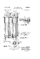
- FIG. 3 is an elevation view of the invention, showingthe outer appearance and adjustment "mechanisms, with the first optical means below a support plate 68 and the second optical means thereabove.
- FIG. 4 is an elevation view in cross section taken through the second optical means which introduces the two star images into the composite image.
- FIG. 5 is an elevation cross-sectional view taken through the line VV of FIG. 3, particularly showing the first optical means which introduces the basic reference markings and azimuth lines into the composite image, and the means for. viewing or photographingfthe composite image.
- FIG. 6 is a plan cross-sectional view taken through line VIVI of FIG. 3, f rther showing a cross-section of the optical sources of the first optical means.
- FIG. 7 is a detail plan view of the reference circle and azimuth adjusting rings for the first optical means viewed as indicated by line VlL-Vll in FIG. 5.
- REG. 8 is a cross-section taken through line VlIL-Vll of FIG. 7, showing the azimuth adjusting rings and optical sources of the first optical means.
- FIG. 9 is an exploded perspective view of the structure disclosed in FIGS. 7 and 8, showing the optical sources of the first optical means.
- FIG. 10 is a detailed cross-sectional view of the optical sources of the adjustable longitude lines.
- FIG. 11 is a detailed plan View of the optical sources of the adjustable longitude lines shown in the cross section of FIG. 10.
- FIG. l2.. is a side view of a portion of the longitude line adjusting mechanism taken on theline XlI-Xll of FIG. 10.
- FEB. 13 is a perspective view of the essential optical elements for forming the composite image and adjusting elements of the invention with the sources of the first optical means exploded.
- FIG. 14 is a sectional view of one of the two tubes supporting the altitude prisms and associated double Dove prism, with central portion of the tube omitted, showing the relationship of the double Dove prism and the azimuthally rotatable tube.
- PEG. 15 is a perspective sectional view of the mechanical arrangement interconnecting the double Dove psism and the tube supporting the altitude prism so that the double Dove prism will rotate half the angle and in the same direction to the altitude prism.
- the essential optical elements for this embodiment of the invention are shown in PEG. 13.
- bracket A Within bracket A are shown in exploded perspective the optical elements which constitute the optical sources of the. basic reference markings, the two azimuth lines and the two adjustable longitude lines.
- light reflecting wires 8 and 9 carried by ring 84 and disc 85 respectively are the optical sources, when illuminated by lamp 94, of the two azimuth lines.
- Transparent disc 83 in ring 32 carries the basic reference markings as light reflecting lines on the transparent disc, namely, circle 1', longitude line 5, latitude lines 3' and 2', as shown in this FIG. 13.
- These lines and circle within transparent disc 88 constitute optical sources when also illuminated by lamp 94.
- Wires 6' and 7 carried by ring 91 are the optical sources of the adjustable longitude lines. These wires 6' and 7 also constitute optical sources when illuminated by lamp Q4. It will be understood that rings 91, 82, 84 and disc when fitted together as shown in FIG. 8, wires 6' and 7', transparent disc 88, wire 8 and wire 9 lie as close together as possible so as to be substantially in the same optical plane.
- the light from azimuth line sources 9 and 8 azimuth circle source 1, latitude and longitude line sources 3' and 5 and latitude line sources 2 and i and longitude line sources 6' and 7 is focused by lens lit-i to form a real image.
- the light emerging from lens 104 is reflected downwardly by semi-transparent mirror 1G6 and to the right by mirror 189, When in the position shown in FIG. 13, through reversing prism 119 so that it may be viewed by an eye-piece composed of lenses 1% and 111.
- Mirror m9 may be moved out from the path between mirror 106 and photographic negative 99 so that the image formed by the lens we will be focused on photographic negative 99. This constitutes the first optical means for forming an image of the basic reference markings, two azimuth lines and adjustable longitude lines.
- the second optical means is shown in FIG. 13 above semi-transparent mirror 166 for introducing, into the image formed by lens 104, the images of the two stars chosen for observation.
- Prism Ztl is adjusted in azimuth and altitude in accordance with the azimuth and computed altitude forthe assume d position of one of the stars and the light from this star passes downwards, preferably through double Dove prism 62 rotatable in azimuth with prism 29 at half the angular rotation thereof and 'inthe same direction, through lens 65, is reflected by mirror 66 and 67 to pass through seim-transparent mirror 106 and by lens 65 is focused in the same optical plane as the image from lens 1454 with the star image located in the composite image on the azimuth line and spaced from the center ofthe azimuth circle in accordance with the differences between the computed and actual altitude, as described above with respect to a hand plot on a Universal Plotting Sheet.
- the image of the other star is introduced into the composite image by prism 21, adjusted with respect to the azimuth and computed altitude for this star, preferably double Dove prism 63 rotatable in azimuth with prism 21 at half the angular rotation. thereof and in the same direction, lens 64, semitransparent mirror 67, and semi-transparent mirror 1%.
- This arrangement constitutes the second optical means referred to above.
- FIGURE 3 There is shown in FIGURE 3, below supporting plate es, the housing for, and the dial that controls, the first optical means for providing to the composite image the basic reference markings, the two azimuth lines and the two adjustable longitude lines.
- Support plate 68 may be a suitable stabilized platform.
- Above plate 68 is the second optical means for providing to the composite image the images of the two stars.
- Below the first optical means is an eye-piece 112 for viewing the composite image and a camera 1% for photographing the composite image.
- the first optical means (below plate 68) has external controls generally indicated at 150 for setting the optical sources of the basic reference markings so that the longitude'lines extend north and south and latitude lines east and west, setting the two azimuth line sources in accordance with the azimuth of the two stars and control 130 for adjusting the two adjustable longitude lines in accordance with the latitude of the assumed position.
- the second optical means (above plate 68) has two prisms 2t) and 21 mounted at the top of their respective rotating tubes 36 and 31, which tubes can be turned about their vertical axes to direct the prisms in accordance with the azimuth angle of the respective stars. These prisms are also rotatable about horizontal axes to be set in accordance with the computed altitude of the respective stars.
- the external controls of the first optical means are set to orient the optical sources of the basic reference markings with azimuth circle center, longitude line, and three latitude lines, and adjustable longitude lines so that in the composite image the 0 mark of the circle represents north, the longitude lines extend north and south, and the latitude lines extend east and west; set to turn the two azimuth line sources so the two azimuth line images have the azimuth direction in the composite image on the azimuth circle corresponding to the azimuth direction of their respective stars; and set to adjust the two adjustable longitude line sources in accordance with the latitude of the assumed position.
- the two prisms are set to the azimuth angle and computed altitude of the two stars.
- the composite image formed by combining the images from the first optical means with the images of the two stars from the second optical means is viewed through the eyepiece or photographed as desired.
- the detailed structure and operation of the first optical means will now be described, particularly with reference to FIGS. 5 through 9.
- the optical sources a 98 is ring- 82.
- Rotatable ring 82 carries transparent disc 88, as most clearly shown in FIG. 9, with the light reflecting markings of the basic reference markings comprising latitude line 3, long to line azimuth circle 1' and latitude lines 2 and 4'.
- Transparent disc 88 is aflixed to side 82' of ring 82 to cover the central hole of ring 82.
- Ring 82 fits within groove 98 in the central opening in housing 98.
- Ring 97 fits within groove 98" in housing 98.
- Ring'97 which is affixed to housing 98 carries marker 72 with respect to which central scale 69 of rotatable ring 82 is.
- Ring 84 which carries light reflecting wire 8 as the optical source of one azimuth line, fits rotatably in groove 82 in ring 82 so that wire 8' is very close to the surface of disc 88 and so that the point about which wire 8' is rotatable coincides with the intersection of markings 3" and 5'.
- ring 84 is rotatable with respect to ring 82 so that wire 8' is rotatable about the center v of the azimuth circle marking on disc 88 with respect to azimuth angle which is read on scale 70 carried by ring 84 with respect to the 0 marking of scale 69' of ring 82.
- Ring 84 is. rotated by clamping ring thereto by clamp 76 which is tapered at end .76 to fit into a slit in ring 85 so that a portion of ring 85 is pressed against ring 84 to fix the two rings together.
- Ring 84 is set by moving both rings together to the proper azimuth reading on scale 70 at mark 73.'
- Ring 85 which carries wire .9, is adapted to fit rotatably within ring 84 with circular disc 85' afi'ixed to ring'85 fitting in groove 84' of 'ring 84 so that the outer.
- transparent disc 83 carries markings 73 and 74 which are angularly aligned with the 0 mark of scale 69 so that azimuth scales 70 and 71 can be readily set with respect to the 0 marking on scale 69, which 0 marking it will be understood to correspond with north.
- Ring 91 which carries within it the structure supto rotatable ring 82 by screws 89 and 90, as shown in- FIG. 8, so that wires 6 and 7. are closely adjacent to and parallel to longitude marking 5' on transparent disc 88. Ring 91'rotates with ring82 sothat wires'6' and 7 are always maintained parallel with longitude mark- 7 7 ing 5. Wires 6' and 7, markings 1', 2, 3', 4, and 5', and
- azimuth'wires 8' and 9' are all illuminated by lamp 94, as shown in FIGS. 5 and 13, to provide illuminated optical sources of these respective elements. located on door 95 having handle 96 so that the lamp may be conveniently replaced.
- the visible light from these optical sources is focused by lens 104 and directed to form an image (with mirror 109 in the dotted line position shown in FIG. 5) on photographic negative 99.
- FIGS. 8 and 9 carried directly below ro- V tatable circularelement or azimuth wheel 82 is circular housing 91, 'aflixed to wheel 82 as by screws 89 and 90.
- housing 91 Within housing 91 are two solid elements 92 and 93,-each having semi-circular cutouts 113 and 114 within which Elements 92 and 93 are slidably are wires 6' and 7'. mounted to be moved perpendicular to wires 6 and'7' along guide members 115 and 116 extending across circular housing 91 as particularly shown in FIG. 9, FIG. 10,
- Wires 6' and 7' are fixed to the upper part of elements 92 and 93 to fit closely beneath transparent disc 88 to provide sources for the longitude lines 6 and 7 in. the composite image shown in FIG. 2.
- the diameter 7 ofthe semi-circles 113 and 114 as here shown is larger than the diameter of the azimuth circle 1 on transparent disc 88.
- Wires 6' and 7' can be adjusted by moving elements 92 and 93 along guides 115 and 116 uniformly from the central position to.the maximum separation corresponding to the diameter of the azimuth circle on disc 88.
- I would correspond to a latitude of 90 at the poles.
- these wires are uniformly separated the maximum distance, they correspond to the longitudelines at the zero latitude, that is, at the equator. Uniformly separated at any distance therebetweenthey can be set to provide images of longitude lines 6" and 7" for any latitude between zero and 90.
- This setting is accomplished 'by providing moveable elements 92 and 93 with elements 121 and 122, respectively, carrying vertical grooves 123 and 124, respectively.
- pins 125 and 126 Adapted to be fit into grooves 123 and 124 are two pins 125 and 126. These are carried on element 127 (FIG. 11) afiixed to the end of shaft 128 extending through casing 98,,and rotatably held outward-by spring 131, and by means of shaft 128, pins 125 and 126 may be pushed into grooves 123 and 124, respectively, and with a turning of knob 130 through 90 elements 92 and 93' and wires 6' and 7' carried thereby may be moved from the 7 position corresponding to zero latitude or 90 latitude, or any latitude position therebetween. With this arrangement the wires 6' and 7' may be adjusted by knob 130 to correspond to any latitude.
- wires 6' and 7', respectively, is adapted to rotate ina.
- Lamp 94 is Knob 130 conveniently carries a scale 132 as seen in FIG, 10, so that the knob may be set in accordance with the latitude in degrees 7 -reference marking images.
- the first optical means is adjusted to set the basic reference markings to correspond with the directions on the earths surface, the two azimuth lines to correspond with the azimuth angles of the respective two stars chosen for observations, and the adjustable longitude lines in accordance with the latitude of the assumed position.
- Disc 88 carrying the basic reference markings is adjusted by hand knob 78 so that the marking on scale 69 causes the 0 marking on reference circle image 1' to correctly indicate north and so that longitude line image 5" extends north and south and latitude line image 3" extends east and west.
- this adjustment may be made by setting the 0 marking on scale 69 to correspond with marking 72. If-the instrument is orientated so that marking 72 indicates the forward direction of the ship or airplane, for example, then the heading will be set on scale 69 to correspond With marking '72 so that the 0 marking points north and the 0 marking on azimuth circle image 1 represents north with respect to the directions on the earths surface and the stars on which observations are to be made. It will be understood that the correct directions for the image of the basic reference markings is required so that the images of the stars 19" and 11" will be properly orientated directionally within the basic When scale 69 has been set, ring 82 may be fixed by turning setscrew 75.
- Ring 34 is turned to coincide with marker 73 on transparent ring 83 so as to set scale 70 at the proper azimuth for one of the stars.
- Disc 85 is turned to set scale 71 to coincide with marker 74, also carried by transparent ring83, so as to set scale 71 at the proper azimuth for the other star.
- Knob 130 is turned to set the two adjustable longitude lines in accordance with the latitude of the assumed position by setting this latitude on scale 132. With all these settings the composite image is provided as shown in FIG. 2 with the exception of stars 19" and 11".
- the second optical means provides to the composite image shown in FIG. 2, the images of 16" and 11" in the proper relationship within this composite image as the points for these stars would be plotted on a Universal Plotting Sheet in accordance with the well known procedure in celestial navigation such that falls on azimuth line 8" at a distance from center of azimuth 1" corresponding to the difference between the computed altitude and the observed altitude for one star, and 11" falls on azimuth line 9" at a distance from center 15" corresponding to the difference between the computed and observed altitude for the other star.
- double Dove prisms 62 and 63 are connected to altitude prism-s 20 and 21, respectively, through tubes 30 and 31, respectively, and through a gear arrangement so that each double Dove prism rotates half the angle of, and the same direction as, the altitude prism to which it is interconnected. This keeps the field of the star images in the proper position in the image while the altitude prisms are rotated in azimuth.
- Prisms 20 and 21 can be directed in azimuth to separate stars and adjusted in elevation 1Q angle according to the computed altitude of their respective stars for an assumed position.
- Prism 21 and its altitud adjusting mechanism are rigidly connected to outer tubing 31.
- Outer tubing 31 is rotatably supported by rotating ring 33, which is supported by stationary ring 35.
- Clamp 41 fixes ring 33 at any desired azimuth position in relation to stationary tube 37.
- Clamp 39 fixes outer tubing 31 at any desired azimuth in relation to rotating ring 33.
- Rotating ring 33 has a ships heading scale 45 around its periphery graduated in degrees from 0 to 360.
- Stationary ring 35 has an index marking 47 associated therewith.
- Rotatable ring 33 is first turned until the ships heading appears above the index 47 on stationary ring 35 so that the azimuth scale 43 for tube 31 will read zero when prism 21 is directed due north. Rotatable ring 33 is then clamped at this heading by clamp 41. Rotatable ring 33 has an index marking 49 which appears directly above 0 on the ships heading scale 45. After the ships heading scale 45 has been set to read the ships heading above index 47,-index 49 will then represent the azimuth of north so that when zero of scale 43 is set at index 49 prism 21 points north. It should be understood that the setting of the ships heading in the invention is only for the purpose of orienting the index 49 so that it reads 0 when the prism points north.
- Rotatable tube 31 is rotated until the chosen stars azimuth appears on scale 43 above index marking 49, and rotatable tube 31 is then clamped in this position by clamp 39.
- the azimuth setting of star scale 43 above index marking 49 which represents north, then positions prism 21 and its associated altitude adjusting mechanism so that they point in azimuth toward the chosen star.
- Prism 20 can be set to any desired azimuth angle in the same manner by its corresponding parts: rotatable tube 39, rotatable ring 32, stationary ring34, and stationary tube 36.
- FIGS. 14 and 15 The preferred arrangement for interconnecting the double Dove prism with the altitude prism is shown particularly in FIGS. 14 and 15.
- altitude prism 21 is rotated in azimuth by turning tube 31.
- gear teeth 160 inside of tube 31 are gear teeth 160, which interconnect with gear teeth 162 carried by the support 163 for double Dove prism 63 which rotates within tube 37.
- Gear teeth are interconnected with gear teeth 162 through a set of three gears 164, 165 and 166 such that movement of gear teeth 160 with rotation of tube 31 causes half the rotation of gear teeth 162 and double Dove prism 63 in the same direction.
- Wrigley Patent 2,505,819 which shows a double Dove prism rotatable about the same vertical axis as an entrance reflecting prism and the effect this has on the image.
- This same arrangement is also preferably applied to interconnect altitude prism 20 with double Dove prism 62.
- prism 21 is adjustable in altitude from zero to 90 by worm gear 27 which is driven by shaft 29, which can be turned by hand knob 133.
- Shaft 29 is attached to rotating tube 31 at its upper end by support 86, and at its lower end by support 151.
- the lower end of shaft 29 is threaded to receive rider 59, which moves up or down when the shaft 29 is turned. Rider 59 is held properly orientated by a groove assembly 18 which receives a tongue 17 attached to the rider.
- the lower end of shaft 29 is covered by a housing 61.
- an opening is cut into housing 61 parallel to shaft 29 to expose the position of rider 59.
- Marked on rider 59 is an index mark 53, which is visible through the opening in housing 61.
- Marked on housing V i1 7 61 along the edge of the opening is an altitude angle degree scale 51 graduated in degrees from to 90.
- shaft 29 is turned by hand knob 133 to adjust the altitude setting of prism 21, the rider 59 is moved correspondingly bythreads 57, and the position of index 53 in relation to degree scale 51 then indicates the degree settingof the prism 21, that. is, the altitudeof star 11".
- the scales of the altitude and azimuth adjustments described for the prisms 2t and 21 is such that the light from the stars will fall in the composite image on their respective azimuth line images at a point proportional to the difference between the star altitude scale setting and the actual'star altitude, such that when the dilference is zero each star image falls at the center of the reference circle image,'and when the difference is 1 each star image falls at the circumference 1" of the reference circle image.
- the lenses 64, 65 and 104 form images having such a relationship and the adjustments for prisms and 21 must be calibrated accordingly.
- eachstar image on its respective azimuth line provides directly the point through which a line of position can be drawn perpendicular to the star azimuth line to provide a line of position'as understood in celestial navigation, and the intersection of two lines of position drawn through the two star images perpendicular to their respective azimuth lines provides.
- an optical device useful in celestial navigation 7 for obtaining a composite representation of an image representing the point of assumed position and'the images of two stars simultaneously as plotted on a Universal Plotting Sheet in celestial navigation for the purpose of ob- V taining a fix, comprising a first optical means forminga first optical path and providing an image of a first star in a focal plane, the entrance optical aperture of said first opticaluneans being adjustable with respect to the altitude and azimuth of said'star, a second means'for forms L in ing an optical image of the point representing the assumed position and introducing said image into said first-optical path and thereby providing in said focal plane an image of a point representing the assumed position, and a third optical means forming a second optical path and introducing an image of'a second star into said first focal plane simultaneously with the image of said first star, the entrance optical aperture of said third optical means being of said star images spaced from the point of assumed posi-. 7
- said first means comprises a first optical means. adjustable in altitude and azimuth for alignment on saidfirst star in accordance with its azimuth and its altitude calculated for the assumed position and .a second optical means associated with said first optical means to' form the image of said first star in a first focal plane
- said third means comprises a first optical means adjustable in altitude and azimuth for alignment on said second star in accordance with its azimuth and its altitude calculated for the assumed position, a second optical means associated with said first optical means for forming the image of said second star in a second focal plane, and means for combining said second focal plane with said first focal plane so that the imagesof said two stars appear in the same focal plane.
- said first means comprises an optical means adjustable in altitude and azimuth for alignment on said first star in accordance with its azimuth and its altitude calculated for the assumed position and a lens associated with said' optical means to form the image of said first star 'in'a first focal plane
- said third means comprises an optical means adjustable in altitude and azimuth for align-. ment on said second star in accordance with itsazimuth and its altitude calculated for the assumed position, a
- said means for combining said second focal plane with said first focal plane comprises a light transmitting and reflecting mirror in the path of the light from said first mentioned lens and a reflecting mirror in the path of V altitude and azimuth 'for alignment on said second 'star' in accordance with its azimuth and its altitude calculated for the assumed position, a lens associated with said prism to -form'the image of said second star in a second focal plane, and means for combining said second focal plane with said first focal of said two stars appear in the same focal plane.
- said-second means includes independent means providing plane so that the images '13 optical sources of two azimuth lines in said focal plane which by means of said lens provide in said composite image, images of an azimuth line for each of said two stars passing through the image of each star and the image of the point representing the assumed position.
- said first means comprises a first optical means adjustable in altitude and azimuth for alignment on said first star in accordance with its azimuth and its altitude calculated for the assumed position and second optical means associated with said first optical means to form the image of said first star in a first focal plane
- said second means comprises an optical source for said basic reference markings, an optical means for forming an image thereof in a second focal plane, and means for combining said second focal plane with said first focal plane so that the images of said first star and said basic reference markings appear in the same focal plane
- said third means comprises a first optical means adjustable in altitude and azimuth for alignment on said second star in accordance with its azimuth and its altitude calculated for the assumed position, a second optical means associated with said first optical means for forming the image of said second star in a third focal plane, and means for combining said third focal plane with said first focal plane so that the images of said two stars and the image of said basic reference markings appear in the same focal plane.
- said first means comprises a first optical means adjustable in altitude and azimuth for alignment on said first star in accordance -with its azimuth and its altitude calculated for the assumed position and a lens associated with said first optical means to form the image of said first star in a first focal plane
- said second means comprises an optical source for said basic reference markings, a lens for forming an image thereof in a second focal plane, and means for combining said second focal plane with said first focal plane so that the images of said first star and said basic reference markings appear in the same focal plane
- said third means comprises a first optical means adjustable in altitude and azimuth for alignment on said second star in accordance with its azimuth and its altitude calculated for the assumed position, .a lens associated with said first optical means for forming the image of said second star in a third focal plane, and means for combining said third focal plane with said first focal plane so that the images of said two stars and the image of said basic reference markings appear in the same focal plane.
- said means for combining said second focal plane with said first focal plane comprises a light transmit-ting and reflecting mirror in the path of the light from said first mentioned lens and a reflecting mirror in the path of the light from said second mentioned lens directing said light toward said reflecting and transmitting mirror
- said means for combining said third focal plane with said first focal plane comprises a light transmitting and reflecting mirror in the path of the light from said first mentioned light transmitting and reflecting mirror and in the path of the light from said second mentioned lens.
- said first means comprises a prism adjustable in altitude and azimuth for alignment on said first star in accordance with its azimuth and its altitude calculated for the assumed position and a lens associated with said prism to form the image of asid first star in a first focal plane
- said second means comprises an optical source for said basic reference markings, a lens for forming an image thereof in a second focal plane, and means for combining said second focal plane with said first focal plane so that the images of said first star and said basic reference markings appear in the same focal plane
- said third means comprises a prism adjustable in altitude and azimuth for alignment on said second star in accordance with its azimuth and its altitude calculated for the assumed position, a lens associated with said prism for forming the image of said second star in a third focal plane, and means for combining said third focal plane with said first focal plane so that the images of said two stars and the image of said basic reference markings appear in the same focal plane.
- said second means comprises an optical source of said basic reference markings and an optical means producing an image thereof in said focal plane, said basic reference markings including a point representing the assumed position latitude and longitude lines intersecting at said point, an azimuth circle with center at said point having a radius corresponding to one degree of latitude, two latitude lines at the points where said longitude line intersects said circle, and in which said second means has associated therewith independent means providing optical sources of two adjustable longitude lines which by means of said lens provide in said composite image, images of two longitude lines adjustable in spacing in accordance with the latitude of the assumed position.
- said second means comprises an optical source of said basic reference markings and an optical means producing an image thereof in said focal plane, said basic reference markings including a point representing the assumed position latitude and longitude lines intersecting at said point, an azimuth circle with center at said point having a radius corresponding to one degree of latitude, two latitude lines at the points where said longitude line intersects said circle, and in which said second means has associated therewith independent means providing optical sources of two adjustable longitude lines which by means of said lens provide in said composite image, images of two longitude lines adjustable in spacing in accordance with the latitude of the assumed position and independent means providing optical sources of two azimuth lines which by means of said lens provide in said composite image, images of an azimuth line for each of said two stars passing through the image of each star and the image of the point representing the assumed position.
- an optical device useful in celestial navigation for obtaining a composite of an indication representing the point of assumed position and the images of two stars simultaneously as plotted on a Universal Plotting Sheet in celestial navigation for the purpose of obtaining a fix, comprising a first optical means forming a first optical path and providing an image of a first star in a focal plane, the entrance optical aperture of said first optical means being adjustable with respect to the altitude and azimuth of said star, a second means providing an indication of the point of assumed position in said focal plane, and a third optical means forming a second optical path and introducing an image of a second star into said first optical path and thereby providing an image of a second star in said focal plane simultaneously with the image of said first star, the entrance optical aperture of said third optical means being adjustable with respect to the altitude and azimuth of said second star,
- said first, second and third means being structurally related in such a way that said indicationfof the point representing the assumed position, the image ofsaid first star, and the imageof said second star appea in said focal'plane as plotted on a Universal Plotting'Sheet with each of said star images spaced from the indication of the point of assumed'position a distance representing the difierence between the altitude for each star calculated for the assumed position and the observed altitudegfor each star, and a line from one star image through the indication of'the point of assumed position corresponds with the azimuth of said star and a line from the other star image through the indication of the point of assumed position corresponds with the azimuth of said other start 16.
- said first and third optical means comprise a reflecting prism rotatable, about a horizontal axis and adjustable with respect to altitude, reach of said prisms being-also rotatable about a vertical axis and means in the optical path from each prism maintaining the field of the star 7 a 7 i5 1 r 1 each double Dove prism rotates halt the azimuthalv angle of the altitude prism and in the. opposite'direction',
- said first and third optical means comprise a periscope having as the optical entrance aperture a reflecting element rotatable about the horizontal axis and a means for observing the image in said reflecting element, and
Landscapes
- Physics & Mathematics (AREA)
- Engineering & Computer Science (AREA)
- Radar, Positioning & Navigation (AREA)
- Remote Sensing (AREA)
- Astronomy & Astrophysics (AREA)
- Automation & Control Theory (AREA)
- General Physics & Mathematics (AREA)
- Instructional Devices (AREA)
Description
y 1962 M. R. PIERCE ET AL 3,046,830
OPTICAL NAVIGATIONAL DEVICE Filed June 17, 1958 8 Sheets-Sheet 5 INVENTORS Mme/6E Z M5265 JAMES 5. 5455220 ,4 TrazA/EM July 31, 1962 M. R. PIERCE ETAL OPTICAL NAVIGATIONAL DEVICE 8 Sheets-Sheet 6 Filed June 17, 1958 INVENTORS Audi/5 2. p/zeca ,4;
M. R. PIERCE ET AL 3,046,830
OPTICAL NAVIGATIONAL DEVICE July 31', 1962 Filed June 17, 1958 8 Sheets-Sheet '7 INVENTORS AfAfl/JE Z F/EECE AND JAA/fi; 6. f-hsszeo A free/vex July 31, 96 M.. R. PIERCE ETAL 3,046,830
OPTICAL NAVIGATIONAL DEVICE Filed June 17, 1958 8 Sheets-Sheet 8 12g 15 INVENTORS MflI/[f Z P/Eidf 44 a JA/Wif 5 1A55f20 3,045,830 OPTECAL NAVIGATIGNAL DEVKJE Maurice R. Pierce, 6400 Primrose Ave, Los Angeles, Qflii, and James S. Fassero, 4622 Loleta Ave., Eagie Roch, (Ialif.
Filed June 17, 1953, Ser. No. 742,535 18 Claims. (Cl. 88-27) This invention relates to an optical device useful in celestial navigation which provides, in a composite image, the images of two celestial bodies along with an image of the reference markings, used in obtaining a fix of position from the intersection of two lines of position derived from observation on and computations for two celestial bodies, as plotted on a Universal Plotting Sheet.
As well known in celestial navigation, a fix point of position is obtained from the intersection of two lines of position as plotted on a Universal Plotting Sheet, published by the Hydrographic Ofiice, in accordance with data obtained by computing the altitudes for two stars for an assumed position and observing the actual altitudes of two stars with a sextant, including a correction arising when the two observations are not simultaneous.
Although the Universal Plotting Sheet does not form a part of the invention, it is believed that the invention will be more easily understood by first briefly describing the known use of such a plotting sheet in obtaining a fix in connection with FIG. 1 of the drawings.
FIG. 1 shows a plot of a fix with two azimuth lines 8 and 9 and two lines of position 12 and 13 hand plotted on a Universal Plotting Sheet derived from azimuth and altitude observations on two stars by means of a sextant and from computations of their altitudes for an assumed position. The Universal Plotting Sheet contains the basic reference markings for the assumed position, particularly including longitude line 5 and latitude line 3 which intersect at 15, representing the assumed position, and an azimuth circle with radius of one degree of latitude marked in degrees from to 360. For convenience longitude line 5 is usually marked off in minutes. Longitude line 5 extends north and south as on a map and latitude line 3 east and west. On the azimuth circle 0 is north, 90 east, 180 south, and 270 west. Latitude lines 2 and 4 at the top and bottom of the circle are included for convenience. It will be understood that longitude line 5, latitude line 3 and azimuth circle 1 constitute the basic reference markings for the assumed position. In the illustration shown in FIG. 1 the assumed position is latitude 50 north and longitude 120 west.
In accordance with celestial navigation procedure, observations are made on the two stars to obtain azimuth direction and altitude of each, and, when the time differ erence between the two observations is significant, a correction is made for the time difierence so that the two values for the observations are those made simultaneously. The altitude of each of the two stars is computed for the assumed position and the difference between the computed and observed altitude obtained for each.
In hand plotting the fix two azimuth lines are drawn through the center 15 of the reference circle 1 to the circumference of the circle through the azimuth markings which correspond to the azimuth angle of the two stars chosen for observation. Thus, line 8 on FIG. 1 is the azimuth line drawn for a star having an azimuth angle of 120, and line 9 is an azimuth line drawn for the second star having an azimuth angle of 220. The altitude difference between the computed and observed altitude of each of the two stars, corrected to simultaneous observation, is marked ofi on the respective azimuth line at a distance measured in minutes from the center 15. The mark is made either in the direction of the star azimuth arrests or in the opposite direction depending on whether .the algebraic difference between the computed altitude and observed altitude is positive or negative that is, depending on whether the observed altitude is low or high compared to the computed altitude. In the example shown in FIG. 1, point 10 represents a negative difference of 18 minutes on the star whose azimuth is 120, that is, the assumed altitude is 18 minutes too high, and point 11 represents a positive difierence of 30 minutes on the star whose azimuth is 220, that is, the assumed altitude is 30 minutes too low. Longitude line 6 is drawn parallel to line 5 through the degree markings on azimuth circle 1 spaced 50 from the mark corresponding to latitude 50 N., for the assumed position, that is, through the 40 and 140 markings, and longitudeline 7 is drawn through the 220 and 320 markings. This gives the proper spacing between the longitude lines for the latitude of the assumed position.
Through each of the points 10 and 11 lines of position 12 and 13 are drawn perpendicular to the appropriate azimuth lines 8 and 9, respectively, and the intersection 14 of the two lines of position is the fix of position. In the example of FIG. 1 the fix shows the position to be latitude 504 north, longitude 46 west.
The two longitude lines 6 and 7 are" drawn in for the purpose of readily reading off the longitude of fix 14. The spacing of each of the two longitude lines 6 and 7 from longitude line 5 will vary from zero at the poles to one degree at the equator. The distance from longitude line 5 to each of the longitude lines 6 and 7 represents 60 minutes of longitude at the latitude of the assumed position. Hence, with these two lines 6 and 7 drawn in, the minutes from longitude line 6, if the fix is located between lines 6 and 5, or from line 5, if it is located between lines 5 and 7, can be readily obtained.
Usually it is not possible to obtain simultaneous altitude observations on the two stars. Corrections must then .be made for the time diiference between the two observations and this is undesirably time-consuming. Moreover, in high-speed aircraft with a lone pilot, it is not only desirable to obtain simultaneous observations on the two stars, but also to obtain as much of the entire plot for the fix as possible as rapidly as possible.
In accordance with the invention not only are the observations of the two stars made simultaneously, but also the images of the two celestial bodies are included in the composite image to provide directlythe two points, such as 10 and 11, in their desired location in the composite image as plotted on a Universal Plotting Sheet for locating the two lines of position and this is obtained without having to observe the altitudes with a sextant, without having to make a correction for lack of simultaneity of the observations, without subtracting to get the difierence between the computed and observed altitudes, and without plotting the points such as 10 and 11 from a calculation of the difference between such observed altitude and the altitude computed for the assumed position. Moreover, in accordance with the preferred arrangement of the invention, as much of the entire data as possible is provided in the composite image along with the images of the two stars, excepting only the two lines of position them selves, so that the fix can be quickly determined by simply drawing only the lines of position through the star images perpendicular to their respective azimuth lines.
Before describing the invention itself, it is believed that it will be more readily understood by a preliminary brief description of such a composite image obtained in accordance with the preferred arrangement of the invention as shown in FIG. 2, where all the data except the lines of position are obtained in the composite image provided by the optical system.
Patented July 31, 19 62 FIG. 2 shows such a composite image produced in I accordance with our invention under the same circumstances which were assumed for the hand plot in the example of FIG. 1.' The composite image contains a reference circle 1"; latitude lines 2", 3", and 4" longitude lines 5", 6", and 7";' and star azimuth lines 8" ,the double-prime correspond to' the elements in FIG. 1
having the same numbers.
In accordance with our invention we have devised an optical device or camera which will provide a composite real optical image, such as shown in FIG. 2, which can be viewed with an eye-piece or photographed. Means are included to produce an image of the basic reference markings for an assumed position, essentially including a latitude line and longitude line-intersecting at a point representing the assumed position, an azimuth circle with markings indicating compass directions, such as appear on a Universal Plotting Sheet, images of two independently adjustable azimuth lines, and the two star images on their respectve azimuth line images at a distance from the assumed position in the image corresponding to the difference between their computed and observed altitudes. Preferably, where it is desired to obtain as much of the usual plot for a fix as possible, means will also be provided for including im'a'ges of the two longitude lines in the composite image adjustable in accordance with the latitude of the assumed position. If desired, means may also be provided for including an image of a clock indicating the time that observations are made and also means providing an image of levels indicating the level of the device. Means are also provided for viewing or photographing this composite image.
Accordingly, it is an object of my invention to provide such an optical device which will quickly give a composite. image of the necessary information for a plot of -a fix for two celestial bodies, including images of the two celestial bodies on images of their azimuth lines in the composite image which are so related to the image of the reference markings thata'fix can be obtained directly from the composite image simply by drawing in the two lines of position through the. star images and perpendicular to the respectiveazimuth lines to obtain their intersection as the fix. a
It is a further object of the invention to provide'such :a device which will give such'a composite image containing all necessary information for. a plot of a fix of position from observations on two celestial bodies such as usually plotted on .a Universal Plotting Sheet, excepting only the lines of position, which can readily be drawnin the image to obtain the fix.
Other and further important objects and advantages of myinvention will be apparent to those skilled in the 7 optical sources in the focal plane of the real composite art from the following description and accompanying drawings.
my invention generally described, there is provided a combination of two optical means for providing the composite image, as referred to above. The first optical means introduces three images into the composite image; namely, (1) an image of the basic reference markings of an as sumed position for plotting a line of position, including the longitude and latitude lines intersecting at the point of the assumed, position and theazimuth circle with azimuth markings such asappears on a printed Universal Plotting Sheet as published by the Hydrographic Ofiice, (2) images of the two azimuth lines, and (3) images of the two adjustable longitude lines. The image (1) of the basic reference markings is rotatable in the plane of the composite image about the image 'of the point of the assumed position, that is, the intersection "15" of lines in the plane of the composite image about this point. lhe
two longitude line images (3) rotate with the image of the basic reference markings so that they are always parallel with the image of longitude line of the assumed 7 position. These two longitude line images are adjustable in their spacing from the image of the longitudeline for,
the assumed position in accordance with the latitudejof. the assumed position. This first optical means .comprises optical sources for these three images and a lens and mirror system for producing a real imageof these image.
The second optical means simultaneously introduces I the images of the two celestial bodies into the composite image, at azimuth positions in the composite image corresponding to their actual azimuths, and is so related to the first optical means that the images of each celestial body falls on its respective azimuth line image at a distance from the point of the assumed position, which, as on a plot on a Universal Plotting Sheet, represents the difference between the computed altitude and the observed altitude. The first and second optical means are so related that when the computed altitude of either celestial body is equal to its actual altitude, the image of the celestial body will fall at the point of the assumed position, and when the actual altitude is one degree different from the computed altitude, the image of' the celestial body will fall on the azimuth circle on its respective azimuth line image at the point where the azimuth line image intersects the azimuth circle image, and when the actual altitude is between zero and one degree different from the computed altitude, the star image will fallon its respective azimuth line image between the-two above mentioned points in accordance with the amount of the difference, in the'same manner as for plotting the points for the two stars on a Universal Plotting Sheet. This second optical means comprises two prisms, one for each of the two stars, independently rotatable in azimuth and altitude for training on each of the two stars, and lens and mirror system for forming images of these two stars in the same focal plane as for the real image produced by the first optical means so that the images of the two.
stars are in the desired composite image.
In addition to the first and second optical means described. above, means are also provided for viewing and for photographing the composite image.
My invention will be described and illustrated by reference. to the specific embodiment thereof shown in the accompanying-drawings in which:
FIG. 1 is arepresentation of a Universal Plot-ting Sheet such as published by the Hydrographic Ofiice with a fix of position hand plotted for two stars having azimuth angles of 120 and 220 respectively, with an assumed position of latitude 50 north and longitude 120 west, and, for this example, an actual position of latitude 504" north and longitude 12046' =west.
FIG. 2 is a composite image produced'by the invention for the same conditions assumed for the hand plot of FIG. 1.
FIG. 3 is an elevation view of the invention, showingthe outer appearance and adjustment "mechanisms, with the first optical means below a support plate 68 and the second optical means thereabove.
FIG. 4 is an elevation view in cross section taken through the second optical means which introduces the two star images into the composite image.
FIG. 5 is an elevation cross-sectional view taken through the line VV of FIG. 3, particularly showing the first optical means which introduces the basic reference markings and azimuth lines into the composite image, and the means for. viewing or photographingfthe composite image.
FIG. 6 is a plan cross-sectional view taken through line VIVI of FIG. 3, f rther showing a cross-section of the optical sources of the first optical means.
FIG. 7 is a detail plan view of the reference circle and azimuth adjusting rings for the first optical means viewed as indicated by line VlL-Vll in FIG. 5.
REG. 8 is a cross-section taken through line VlIL-Vll of FIG. 7, showing the azimuth adjusting rings and optical sources of the first optical means.
FIG. 9 is an exploded perspective view of the structure disclosed in FIGS. 7 and 8, showing the optical sources of the first optical means.
FIG. 10 is a detailed cross-sectional view of the optical sources of the adjustable longitude lines.
FIG. 11 is a detailed plan View of the optical sources of the adjustable longitude lines shown in the cross section of FIG. 10.
FIG. l2..is a side view of a portion of the longitude line adjusting mechanism taken on theline XlI-Xll of FIG. 10.
FEB. 13 is a perspective view of the essential optical elements for forming the composite image and adjusting elements of the invention with the sources of the first optical means exploded.
FIG. 14 is a sectional view of one of the two tubes supporting the altitude prisms and associated double Dove prism, with central portion of the tube omitted, showing the relationship of the double Dove prism and the azimuthally rotatable tube.
PEG. 15 is a perspective sectional view of the mechanical arrangement interconnecting the double Dove psism and the tube supporting the altitude prism so that the double Dove prism will rotate half the angle and in the same direction to the altitude prism.
The essential optical elements for this embodiment of the invention are shown in PEG. 13. Within bracket A are shown in exploded perspective the optical elements which constitute the optical sources of the. basic reference markings, the two azimuth lines and the two adjustable longitude lines. Thus light reflecting wires 8 and 9 carried by ring 84 and disc 85 respectively, are the optical sources, when illuminated by lamp 94, of the two azimuth lines. Transparent disc 83 in ring 32 carries the basic reference markings as light reflecting lines on the transparent disc, namely, circle 1', longitude line 5, latitude lines 3' and 2', as shown in this FIG. 13. These lines and circle within transparent disc 88 constitute optical sources when also illuminated by lamp 94. Wires 6' and 7 carried by ring 91 are the optical sources of the adjustable longitude lines. These wires 6' and 7 also constitute optical sources when illuminated by lamp Q4. It will be understood that rings 91, 82, 84 and disc when fitted together as shown in FIG. 8, wires 6' and 7', transparent disc 88, wire 8 and wire 9 lie as close together as possible so as to be substantially in the same optical plane. The light from azimuth line sources 9 and 8, azimuth circle source 1, latitude and longitude line sources 3' and 5 and latitude line sources 2 and i and longitude line sources 6' and 7 is focused by lens lit-i to form a real image. The light emerging from lens 104, however, is reflected downwardly by semi-transparent mirror 1G6 and to the right by mirror 189, When in the position shown in FIG. 13, through reversing prism 119 so that it may be viewed by an eye-piece composed of lenses 1% and 111. Mirror m9 may be moved out from the path between mirror 106 and photographic negative 99 so that the image formed by the lens we will be focused on photographic negative 99. This constitutes the first optical means for forming an image of the basic reference markings, two azimuth lines and adjustable longitude lines.
The second optical means is shown in FIG. 13 above semi-transparent mirror 166 for introducing, into the image formed by lens 104, the images of the two stars chosen for observation. Prism Ztl is adjusted in azimuth and altitude in accordance with the azimuth and computed altitude forthe assume d position of one of the stars and the light from this star passes downwards, preferably through double Dove prism 62 rotatable in azimuth with prism 29 at half the angular rotation thereof and 'inthe same direction, through lens 65, is reflected by mirror 66 and 67 to pass through seim-transparent mirror 106 and by lens 65 is focused in the same optical plane as the image from lens 1454 with the star image located in the composite image on the azimuth line and spaced from the center ofthe azimuth circle in accordance with the differences between the computed and actual altitude, as described above with respect to a hand plot on a Universal Plotting Sheet. In the same manner the image of the other star is introduced into the composite image by prism 21, adjusted with respect to the azimuth and computed altitude for this star, preferably double Dove prism 63 rotatable in azimuth with prism 21 at half the angular rotation. thereof and in the same direction, lens 64, semitransparent mirror 67, and semi-transparent mirror 1%. This arrangement constitutes the second optical means referred to above.
Thus by the combination of the first optical means and the second optical means a composite image is produced 1 on photographic negative 99 (with mirror 109 moved out Cir of position as shown at 169 by dotted lines in Fl- URE 5).
There is shown in FIGURE 3, below supporting plate es, the housing for, and the dial that controls, the first optical means for providing to the composite image the basic reference markings, the two azimuth lines and the two adjustable longitude lines. Support plate 68 may be a suitable stabilized platform. Above plate 68 is the second optical means for providing to the composite image the images of the two stars. Below the first optical means is an eye-piece 112 for viewing the composite image and a camera 1% for photographing the composite image.
The first optical means (below plate 68) has external controls generally indicated at 150 for setting the optical sources of the basic reference markings so that the longitude'lines extend north and south and latitude lines east and west, setting the two azimuth line sources in accordance with the azimuth of the two stars and control 130 for adjusting the two adjustable longitude lines in accordance with the latitude of the assumed position. The second optical means (above plate 68) has two prisms 2t) and 21 mounted at the top of their respective rotating tubes 36 and 31, which tubes can be turned about their vertical axes to direct the prisms in accordance with the azimuth angle of the respective stars. These prisms are also rotatable about horizontal axes to be set in accordance with the computed altitude of the respective stars.
In the use of the invention, the external controls of the first optical means are set to orient the optical sources of the basic reference markings with azimuth circle center, longitude line, and three latitude lines, and adjustable longitude lines so that in the composite image the 0 mark of the circle represents north, the longitude lines extend north and south, and the latitude lines extend east and west; set to turn the two azimuth line sources so the two azimuth line images have the azimuth direction in the composite image on the azimuth circle corresponding to the azimuth direction of their respective stars; and set to adjust the two adjustable longitude line sources in accordance with the latitude of the assumed position. The two prisms are set to the azimuth angle and computed altitude of the two stars. The composite image formed by combining the images from the first optical means with the images of the two stars from the second optical means is viewed through the eyepiece or photographed as desired. The detailed structure and operation of the first optical means will now be described, particularly with reference to FIGS. 5 through 9. As shown in FIGS. 5 and 6, and also in FIG. 3 below plate 68, the optical sources a 98 is ring- 82.
afiixed to housing 98 by screws 81. Rotatable ring 82 carries transparent disc 88, as most clearly shown in FIG. 9, with the light reflecting markings of the basic reference markings comprising latitude line 3, longitudine line azimuth circle 1' and latitude lines 2 and 4'. Transparent disc 88 is aflixed to side 82' of ring 82 to cover the central hole of ring 82. Ring 82 fits within groove 98 in the central opening in housing 98. Ring 97 fits within groove 98" in housing 98. Ring'97 which is affixed to housing 98 carries marker 72 with respect to which central scale 69 of rotatable ring 82 is. set to orientate the basic reference markings on transparent disc 88 in the composite image so that, correlated with the images of the stars from the prisms of the first optical means, the longitude lines extend north and south and the latitude lines east and west and so that the 0 marking on the azimuth circle points north. It will be understood that this may be accomplished by directing the device north and south andsetting the 0 on scale 69 to mark 72, or by orientating the device fore and aft 7 of the ship or plane and setting the heading on scale 69 opposite marker 72 so that the 0 mark on scale 69 points north. This adjustment isobtained by'rotating ring 82 by way of turning knob 78 afiixed' thereto and V is clamped in set position by knob 75, which is tapered at its end 75' to fit into a slit so that a portion of ring 82 expands against housing 98 to fix ring 82 in position.
7' porting adjustably longitude wires 6' and 7, is afiixed Ring 84, which carries light reflecting wire 8 as the optical source of one azimuth line, fits rotatably in groove 82 in ring 82 so that wire 8' is very close to the surface of disc 88 and so that the point about which wire 8' is rotatable coincides with the intersection of markings 3" and 5'. Thus ring 84 is rotatable with respect to ring 82 so that wire 8' is rotatable about the center v of the azimuth circle marking on disc 88 with respect to azimuth angle which is read on scale 70 carried by ring 84 with respect to the 0 marking of scale 69' of ring 82. That is, for example, a setting of 0 on scale 78 corresponding to 0 on scale 69 would represent an'azimuth of due north and a setting of on scale to correspond with the Q on the scale 69 would correspond with an azimuth of 60. Ring 84 is. rotated by clamping ring thereto by clamp 76 which is tapered at end .76 to fit into a slit in ring 85 so that a portion of ring 85 is pressed against ring 84 to fix the two rings together. Ring 84 is set by moving both rings together to the proper azimuth reading on scale 70 at mark 73.'
' surface of disc. 85' is substantially flush with the outer surface of ring 84'carrying scale 70. When clamp 76 is released ring 85 can be rotated independently of ring'84. Ring85 carries wire 9' and'when ring 85 is rotatably fit within ring 84 wire 9' is closely adjacent to wire 8 and, like wire 8, is rotatable about the center of azimuth circle '1' by turning knobr79 which turns' disc 85' and ring 85 so that the proper azimuth can be set on scale 71 at mark 74. Transparent ring 83 is affixed to the surface of ring 82 over scale 69 and'extends, as particularly shownin FIGS. 7 and 8, over scale 70 of ring 84 and scale 71 of disc 85. As shown in FIGS. 7 and 8, transparent disc 83 carries markings 73 and 74 which are angularly aligned with the 0 mark of scale 69 so that azimuth scales 70 and 71 can be readily set with respect to the 0 marking on scale 69, which 0 marking it will be understood to correspond with north. a
azimuth'wires 8' and 9' are all illuminated by lamp 94, as shown in FIGS. 5 and 13, to provide illuminated optical sources of these respective elements. located on door 95 having handle 96 so that the lamp may be conveniently replaced. The visible light from these optical sources is focused by lens 104 and directed to form an image (with mirror 109 in the dotted line position shown in FIG. 5) on photographic negative 99.
The detailed structure of the mechanism for adjusting the two wires 6' and 7, will now be explained in connection with FIGS. .9, l0, and-1l, and 12. As shown particularly in FIGS. 8 and 9, carried directly below ro- V tatable circularelement or azimuth wheel 82 is circular housing 91, 'aflixed to wheel 82 as by screws 89 and 90. Within housing 91 are two solid elements 92 and 93,-each having semi-circular cutouts 113 and 114 within which Elements 92 and 93 are slidably are wires 6' and 7'. mounted to be moved perpendicular to wires 6 and'7' along guide members 115 and 116 extending across circular housing 91 as particularly shown in FIG. 9, FIG. 10,
and FIG. 11, and extending through holes 117 and 118 in element 92 and holes 119 and 120 in element 93.
Wires 6' and 7' are fixed to the upper part of elements 92 and 93 to fit closely beneath transparent disc 88 to provide sources for the longitude lines 6 and 7 in. the composite image shown in FIG. 2. The diameter 7 ofthe semi-circles 113 and 114 as here shown is larger than the diameter of the azimuth circle 1 on transparent disc 88.
Wires 6' and 7' can be adjusted by moving elements 92 and 93 along guides 115 and 116 uniformly from the central position to.the maximum separation corresponding to the diameter of the azimuth circle on disc 88.
I would correspond to a latitude of 90 at the poles. When these wires are uniformly separated the maximum distance, they correspond to the longitudelines at the zero latitude, that is, at the equator. Uniformly separated at any distance therebetweenthey can be set to provide images of longitude lines 6" and 7" for any latitude between zero and 90. 9
This setting is accomplished 'by providing moveable elements 92 and 93 with elements 121 and 122, respectively, carrying vertical grooves 123 and 124, respectively.
' Adapted to be fit into grooves 123 and 124 are two pins 125 and 126. These are carried on element 127 (FIG. 11) afiixed to the end of shaft 128 extending through casing 98,,and rotatably held outward-by spring 131, and by means of shaft 128, pins 125 and 126 may be pushed into grooves 123 and 124, respectively, and with a turning of knob 130 through 90 elements 92 and 93' and wires 6' and 7' carried thereby may be moved from the 7 position corresponding to zero latitude or 90 latitude, or any latitude position therebetween. With this arrangement the wires 6' and 7' may be adjusted by knob 130 to correspond to any latitude.
wires 6' and 7', respectively, is adapted to rotate ina.
horizontal plane along with and affixed to azimuth wheel 82 carrying plate 88; and that, therefore, in accordance with the arrangement here shown the adjustment of the position of longitude wires 6 and 7' can be made only Lamp 94 is Knob 130 conveniently carries a scale 132 as seen in FIG, 10, so that the knob may be set in accordance with the latitude in degrees 7 -reference marking images.
9 when azimuth wheel 82 is in the position so that pins 125 and 126 can engage grooves 123 and 124, which as here shown is when th zero degree marking on the azimuth wheel 82 is as shown in FIG. 11.
In operation, the first optical means, the structural parts of which are described above, and shown particularly in FIGS. 5 and 9, is adjusted to set the basic reference markings to correspond with the directions on the earths surface, the two azimuth lines to correspond with the azimuth angles of the respective two stars chosen for observations, and the adjustable longitude lines in accordance with the latitude of the assumed position. Disc 88 carrying the basic reference markings is adjusted by hand knob 78 so that the marking on scale 69 causes the 0 marking on reference circle image 1' to correctly indicate north and so that longitude line image 5" extends north and south and latitude line image 3" extends east and west. If the instrument is orientated so that arrow marking 72 points north, then this adjustment may be made by setting the 0 marking on scale 69 to correspond with marking 72. If-the instrument is orientated so that marking 72 indicates the forward direction of the ship or airplane, for example, then the heading will be set on scale 69 to correspond With marking '72 so that the 0 marking points north and the 0 marking on azimuth circle image 1 represents north with respect to the directions on the earths surface and the stars on which observations are to be made. It will be understood that the correct directions for the image of the basic reference markings is required so that the images of the stars 19" and 11" will be properly orientated directionally within the basic When scale 69 has been set, ring 82 may be fixed by turning setscrew 75. Ring 34 is turned to coincide with marker 73 on transparent ring 83 so as to set scale 70 at the proper azimuth for one of the stars. Disc 85 is turned to set scale 71 to coincide with marker 74, also carried by transparent ring83, so as to set scale 71 at the proper azimuth for the other star. Knob 130 is turned to set the two adjustable longitude lines in accordance with the latitude of the assumed position by setting this latitude on scale 132. With all these settings the composite image is provided as shown in FIG. 2 with the exception of stars 19" and 11".
The second optical means provides to the composite image shown in FIG. 2, the images of 16" and 11" in the proper relationship within this composite image as the points for these stars would be plotted on a Universal Plotting Sheet in accordance with the well known procedure in celestial navigation such that falls on azimuth line 8" at a distance from center of azimuth 1" corresponding to the difference between the computed altitude and the observed altitude for one star, and 11" falls on azimuth line 9" at a distance from center 15" corresponding to the difference between the computed and observed altitude for the other star.
The detailed structure and operation of the second optical means, which introduces the two star images into the composite image, will be explained particularly in connection with FIGS. 3 and 4. Referring to FIG. 4, light from the two stars 10' and 11' passes first through prisms and 21, which are mounted on rotating tubes 30 and 31. Prisms 20 and 21 are rotatable in elevation angle by their respective worm gear elevation drives 25 and 27. Prisms 20 and 21 are rotatable in azimuth by their respective rotating tubes and 31. By an interconnecting mechanical arrangement, described in detail below, double Dove prisms 62 and 63 are connected to altitude prism- s 20 and 21, respectively, through tubes 30 and 31, respectively, and through a gear arrangement so that each double Dove prism rotates half the angle of, and the same direction as, the altitude prism to which it is interconnected. This keeps the field of the star images in the proper position in the image while the altitude prisms are rotated in azimuth. Prisms 20 and 21 can be directed in azimuth to separate stars and adjusted in elevation 1Q angle according to the computed altitude of their respective stars for an assumed position.
The operation of setting the prisms to the proper azi-' muth angle will be described by using prism 21 as an example. Prism 21 and its altitud adjusting mechanism are rigidly connected to outer tubing 31. Outer tubing 31 is rotatably supported by rotating ring 33, which is supported by stationary ring 35. Clamp 41 fixes ring 33 at any desired azimuth position in relation to stationary tube 37. Clamp 39 fixes outer tubing 31 at any desired azimuth in relation to rotating ring 33. Rotating ring 33 has a ships heading scale 45 around its periphery graduated in degrees from 0 to 360. Stationary ring 35 has an index marking 47 associated therewith. To direct prism 21 to the azimuth of any chosen star, rotatable ring 33 is first turned until the ships heading appears above the index 47 on stationary ring 35 so that the azimuth scale 43 for tube 31 will read zero when prism 21 is directed due north. Rotatable ring 33 is then clamped at this heading by clamp 41. Rotatable ring 33 has an index marking 49 which appears directly above 0 on the ships heading scale 45. After the ships heading scale 45 has been set to read the ships heading above index 47,-index 49 will then represent the azimuth of north so that when zero of scale 43 is set at index 49 prism 21 points north. It should be understood that the setting of the ships heading in the invention is only for the purpose of orienting the index 49 so that it reads 0 when the prism points north. It is important that the reading on scale 43 be 0 when the prism is directed north. Rotatable tube 31 is rotated until the chosen stars azimuth appears on scale 43 above index marking 49, and rotatable tube 31 is then clamped in this position by clamp 39. The azimuth setting of star scale 43 above index marking 49, which represents north, then positions prism 21 and its associated altitude adjusting mechanism so that they point in azimuth toward the chosen star. Prism 20 can be set to any desired azimuth angle in the same manner by its corresponding parts: rotatable tube 39, rotatable ring 32, stationary ring34, and stationary tube 36.
The preferred arrangement for interconnecting the double Dove prism with the altitude prism is shown particularly in FIGS. 14 and 15. As described above, altitude prism 21 is rotated in azimuth by turning tube 31. As shown in FIG. 15, inside of tube 31 are gear teeth 160, which interconnect with gear teeth 162 carried by the support 163 for double Dove prism 63 which rotates within tube 37. Gear teeth are interconnected with gear teeth 162 through a set of three gears 164, 165 and 166 such that movement of gear teeth 160 with rotation of tube 31 causes half the rotation of gear teeth 162 and double Dove prism 63 in the same direction. Reference is made to Wrigley Patent 2,505,819 which shows a double Dove prism rotatable about the same vertical axis as an entrance reflecting prism and the effect this has on the image. This same arrangement is also preferably applied to interconnect altitude prism 20 with double Dove prism 62.
The prism altitude adjusting mechanisms will be described using prism 21 as an example. Refer-ring to FIG. 4, prism 21 is adjustable in altitude from zero to 90 by worm gear 27 which is driven by shaft 29, which can be turned by hand knob 133. Shaft 29 is attached to rotating tube 31 at its upper end by support 86, and at its lower end by support 151. The lower end of shaft 29 is threaded to receive rider 59, which moves up or down when the shaft 29 is turned. Rider 59 is held properly orientated by a groove assembly 18 which receives a tongue 17 attached to the rider. The lower end of shaft 29 is covered by a housing 61.
Referring to FIG. 4, an opening is cut into housing 61 parallel to shaft 29 to expose the position of rider 59. Marked on rider 59 is an index mark 53, which is visible through the opening in housing 61. Marked on housing V i1 7 61 along the edge of the opening is an altitude angle degree scale 51 graduated in degrees from to 90. When shaft 29 is turned by hand knob 133 to adjust the altitude setting of prism 21, the rider 59 is moved correspondingly bythreads 57, and the position of index 53 in relation to degree scale 51 then indicates the degree settingof the prism 21, that. is, the altitudeof star 11".
Rigidly attachedto the bottom of shaft 29 below housing .61 is a disc on which is marked an altitude minute scale 55 graduated in minutes from 0 to 60. Marked on housing61 above scale 55 is an index mark M31. The minute reading appearing below index 101 on scale 55 indicates the altitude setting of prism 21 in minutes. Thus to set prism 21 to any desired altitude, hand knob 133 isturned until the desired altitude reading appears on the degree and minut scales opposite their respective indices. Prism 20 can be set to any desired altitude in the same manner by its corresponding parts.
. When prisms 20 and 21 are directed in azimuth and altitude toward their respectivestars, and 11", thestar light passes through prisms 20 and 21, through prisms 62 and 63 and stationary telephoto lenses 65 and 64 to mirrors 66 and 67. Mirror 66 is a totally reflecting mirror which directs the star light from telephoto lens .65 to mirror 67. Mirror 67 is a 50% reflecting mirror,
so thatstar light coming from lens 64- to mirror 67 is' passed. downward at half intensity. Star light coming from mirror 66 is reflected downward at'half intensity. Thus from mirror 67 star light from both stars is transmitted downward through mirror 106 shown in FIG. 13 and is combined with the reference images to form the composite image. The scales of the altitude and azimuth adjustments described for the prisms 2t and 21 is such that the light from the stars will fall in the composite image on their respective azimuth line images at a point proportional to the difference between the star altitude scale setting and the actual'star altitude, such that when the dilference is zero each star image falls at the center of the reference circle image,'and when the difference is 1 each star image falls at the circumference 1" of the reference circle image. For this purpose the lenses 64, 65 and 104 form images having such a relationship and the adjustments for prisms and 21 must be calibrated accordingly.
When the azimuth relationship of the images formed in the first optical means is adjusted-to correspond for a fix of position on two specific stars, and with the prisms 20 and 21 set to the star azimuths, the star images-10" and 11', will fall on their respective star azimuth lines 8" and-9" in the composite image, as illustrated in FIG. 2. Furthermore, when prisms 20 and 21 are set in altitude to the computed altitude of their respective stars Ill and 11' for the assumed position, the star images will fall on their respective azimuth lines' at a distance from the reference circle center 15" which is determined by the difierence between the computed and the actual star altitudes. Therefore, the position of eachstar image on its respective azimuth line provides directly the point through which a line of position can be drawn perpendicular to the star azimuth line to provide a line of position'as understood in celestial navigation, and the intersection of two lines of position drawn through the two star images perpendicular to their respective azimuth lines provides.
a fix of position as understood in celestial navigation.
We claim: 1. In an optical device, useful in celestial navigation 7 for obtaining a composite representation of an image representing the point of assumed position and'the images of two stars simultaneously as plotted on a Universal Plotting Sheet in celestial navigation for the purpose of ob- V taining a fix, comprising a first optical means forminga first optical path and providing an image of a first star in a focal plane, the entrance optical aperture of said first opticaluneans being adjustable with respect to the altitude and azimuth of said'star, a second means'for forms L in ing an optical image of the point representing the assumed position and introducing said image into said first-optical path and thereby providing in said focal plane an image of a point representing the assumed position, and a third optical means forming a second optical path and introducing an image of'a second star into said first focal plane simultaneously with the image of said first star, the entrance optical aperture of said third optical means being of said star images spaced from the point of assumed posi-. 7
tion a distance representing the difierence between the. altitude for each star calculated'for the assumed position and the observed altitude for each star, and a line from one star image through the point of assumed position corresponds withthe azimuth of said star and a line from the other star image through the point of assumed position corresponds with the azimuth of said other star.
2. An optical device as defined .in claim 1 in which said first means comprises a first optical means. adjustable in altitude and azimuth for alignment on saidfirst star in accordance with its azimuth and its altitude calculated for the assumed position and .a second optical means associated with said first optical means to' form the image of said first star in a first focal plane, and" said third means comprises a first optical means adjustable in altitude and azimuth for alignment on said second star in accordance with its azimuth and its altitude calculated for the assumed position, a second optical means associated with said first optical means for forming the image of said second star in a second focal plane, and means for combining said second focal plane with said first focal plane so that the imagesof said two stars appear in the same focal plane.
. 3. An optical device as defined in claim 1 in which said first means comprises an optical means adjustable in altitude and azimuth for alignment on said first star in accordance with its azimuth and its altitude calculated for the assumed position and a lens associated with said' optical means to form the image of said first star 'in'a first focal plane, and saidthird means comprises an optical means adjustable in altitude and azimuth for align-. ment on said second star in accordance with itsazimuth and its altitude calculated for the assumed position, a
lens associated with said optical means for forming the; image of said second star in a second focal plane, and
means for combining said second focal plane with said first focal plane so that the images of said two stars appear in the same focal plane.
4. An optical device as defined in claim 3 in which said means for combining said second focal plane with said first focal plane comprises a light transmitting and reflecting mirror in the path of the light from said first mentioned lens and a reflecting mirror in the path of V altitude and azimuth 'for alignment on said second 'star' in accordance with its azimuth and its altitude calculated for the assumed position, a lens associated with said prism to -form'the image of said second star in a second focal plane, and means for combining said second focal plane with said first focal of said two stars appear in the same focal plane. 1
6. An optical device as defined in claim 1 in which said-second means includes independent means providing plane so that the images '13 optical sources of two azimuth lines in said focal plane which by means of said lens provide in said composite image, images of an azimuth line for each of said two stars passing through the image of each star and the image of the point representing the assumed position.
7. An optical device as defined in claim 6 in which said independent means for providing said azimuth lines are rotatable about the means providing for the point of assumed position in said focal plane so that said azimuth lines are adjustable in accordance With the azimuth of the respective stars.
8. An optical device as defined in claim 1 in which said first means comprises a first optical means adjustable in altitude and azimuth for alignment on said first star in accordance with its azimuth and its altitude calculated for the assumed position and second optical means associated with said first optical means to form the image of said first star in a first focal plane, said second means comprises an optical source for said basic reference markings, an optical means for forming an image thereof in a second focal plane, and means for combining said second focal plane with said first focal plane so that the images of said first star and said basic reference markings appear in the same focal plane, and said third means comprises a first optical means adjustable in altitude and azimuth for alignment on said second star in accordance with its azimuth and its altitude calculated for the assumed position, a second optical means associated with said first optical means for forming the image of said second star in a third focal plane, and means for combining said third focal plane with said first focal plane so that the images of said two stars and the image of said basic reference markings appear in the same focal plane.
9. An optical device as defined in claim 1 in which said first means comprises a first optical means adjustable in altitude and azimuth for alignment on said first star in accordance -with its azimuth and its altitude calculated for the assumed position and a lens associated with said first optical means to form the image of said first star in a first focal plane, said second means comprises an optical source for said basic reference markings, a lens for forming an image thereof in a second focal plane, and means for combining said second focal plane with said first focal plane so that the images of said first star and said basic reference markings appear in the same focal plane, and said third means comprises a first optical means adjustable in altitude and azimuth for alignment on said second star in accordance with its azimuth and its altitude calculated for the assumed position, .a lens associated with said first optical means for forming the image of said second star in a third focal plane, and means for combining said third focal plane with said first focal plane so that the images of said two stars and the image of said basic reference markings appear in the same focal plane.
10. An optical device as defined in claim 9 in which said means for combining said second focal plane with said first focal plane comprises a light transmit-ting and reflecting mirror in the path of the light from said first mentioned lens and a reflecting mirror in the path of the light from said second mentioned lens directing said light toward said reflecting and transmitting mirror, and said means for combining said third focal plane with said first focal plane comprises a light transmitting and reflecting mirror in the path of the light from said first mentioned light transmitting and reflecting mirror and in the path of the light from said second mentioned lens.
11. An optical device as defined in claim 1 in which said first means comprises a prism adjustable in altitude and azimuth for alignment on said first star in accordance with its azimuth and its altitude calculated for the assumed position and a lens associated with said prism to form the image of asid first star in a first focal plane, said second means comprises an optical source for said basic reference markings, a lens for forming an image thereof in a second focal plane, and means for combining said second focal plane with said first focal plane so that the images of said first star and said basic reference markings appear in the same focal plane, and said third means comprises a prism adjustable in altitude and azimuth for alignment on said second star in accordance with its azimuth and its altitude calculated for the assumed position, a lens associated with said prism for forming the image of said second star in a third focal plane, and means for combining said third focal plane with said first focal plane so that the images of said two stars and the image of said basic reference markings appear in the same focal plane.
12. An optical device as defined in claim 1 in which said second means comprises an optical source of said basic reference markings and an optical means producing an image thereof in said focal plane, and in which said second means has associated therewith independent means providing optical sources of two adjustable longitude lines which by means of said lens provide in said composite image, images of two longitude lines adjustable in spacing in accordance with the'latitude of the assumed position.
13. An optical device as defined in claim 1 in which said second means comprises an optical source of said basic reference markings and an optical means producing an image thereof in said focal plane, said basic reference markings including a point representing the assumed position latitude and longitude lines intersecting at said point, an azimuth circle with center at said point having a radius corresponding to one degree of latitude, two latitude lines at the points where said longitude line intersects said circle, and in which said second means has associated therewith independent means providing optical sources of two adjustable longitude lines which by means of said lens provide in said composite image, images of two longitude lines adjustable in spacing in accordance with the latitude of the assumed position.
14. An optical device as defined in claim 1 in which said second means comprises an optical source of said basic reference markings and an optical means producing an image thereof in said focal plane, said basic reference markings including a point representing the assumed position latitude and longitude lines intersecting at said point, an azimuth circle with center at said point having a radius corresponding to one degree of latitude, two latitude lines at the points where said longitude line intersects said circle, and in which said second means has associated therewith independent means providing optical sources of two adjustable longitude lines which by means of said lens provide in said composite image, images of two longitude lines adjustable in spacing in accordance with the latitude of the assumed position and independent means providing optical sources of two azimuth lines which by means of said lens provide in said composite image, images of an azimuth line for each of said two stars passing through the image of each star and the image of the point representing the assumed position.
15. In an optical device, useful in celestial navigation for obtaining a composite of an indication representing the point of assumed position and the images of two stars simultaneously as plotted on a Universal Plotting Sheet in celestial navigation for the purpose of obtaining a fix, comprising a first optical means forming a first optical path and providing an image of a first star in a focal plane, the entrance optical aperture of said first optical means being adjustable with respect to the altitude and azimuth of said star, a second means providing an indication of the point of assumed position in said focal plane, and a third optical means forming a second optical path and introducing an image of a second star into said first optical path and thereby providing an image of a second star in said focal plane simultaneously with the image of said first star, the entrance optical aperture of said third optical means being adjustable with respect to the altitude and azimuth of said second star,
Y 1-5- 7 said first, second and third means being structurally related in such a way that said indicationfof the point representing the assumed position, the image ofsaid first star, and the imageof said second star appea in said focal'plane as plotted on a Universal Plotting'Sheet with each of said star images spaced from the indication of the point of assumed'position a distance representing the difierence between the altitude for each star calculated for the assumed position and the observed altitudegfor each star, and a line from one star image through the indication of'the point of assumed position corresponds with the azimuth of said star and a line from the other star image through the indication of the point of assumed position corresponds with the azimuth of said other start 16. In an optical device as defined in claim 1 in which said first and third optical means comprise a reflecting prism rotatable, about a horizontal axis and adjustable with respect to altitude, reach of said prisms being-also rotatable about a vertical axis and means in the optical path from each prism maintaining the field of the star 7 a 7 i5 1 r 1 each double Dove prism rotates halt the azimuthalv angle of the altitude prism and in the. opposite'direction',
; 18. In an optical device as defined in claim 1 inwhich said first and third optical means comprise a periscope having as the optical entrance aperture a reflecting element rotatable about the horizontal axis anda means for observing the image in said reflecting element, and
in the optical path between said reflecting element and said means for observ ng said image'a means maintaining the field of view in the proper position as said re-' fleeting element is rotated in azimuth about said vertical axis. 7
References Cited in the file of this patent UNITED STATES PATENTS 886,722 Neumayer May 5, 1908 1,160,184 .Mackensen Nov. 16, 1915' 2,064,062 Hagner Dec. 15, 1936 2,471,686 Hiltner May 31, 1949 2,505,819 Wrigley May 2, 1950 2,688,896 Tripp Sept. 14,1954 2,930,545 Houle et al Mar. 29, 1960 p FOREIGN PATENTS 840,326 France 4 Jan. 16, 1939 610,561 Great Britain Oct. 18, 1948
Priority Applications (1)
| Application Number | Priority Date | Filing Date | Title |
|---|---|---|---|
| US742535A US3046830A (en) | 1958-06-17 | 1958-06-17 | Optical navigational device |
Applications Claiming Priority (1)
| Application Number | Priority Date | Filing Date | Title |
|---|---|---|---|
| US742535A US3046830A (en) | 1958-06-17 | 1958-06-17 | Optical navigational device |
Publications (1)
| Publication Number | Publication Date |
|---|---|
| US3046830A true US3046830A (en) | 1962-07-31 |
Family
ID=24985210
Family Applications (1)
| Application Number | Title | Priority Date | Filing Date |
|---|---|---|---|
| US742535A Expired - Lifetime US3046830A (en) | 1958-06-17 | 1958-06-17 | Optical navigational device |
Country Status (1)
| Country | Link |
|---|---|
| US (1) | US3046830A (en) |
Cited By (2)
| Publication number | Priority date | Publication date | Assignee | Title |
|---|---|---|---|---|
| US4294541A (en) * | 1979-06-18 | 1981-10-13 | Abler William L | Bi-periscopic instrument for use in determining terrestrial positions through celestial observation |
| US4462684A (en) * | 1981-10-09 | 1984-07-31 | Abler William L | Single wheel celestial navigator |
Citations (9)
| Publication number | Priority date | Publication date | Assignee | Title |
|---|---|---|---|---|
| US886722A (en) * | 1907-02-12 | 1908-05-05 | Firm Of Optische Anstalt C P Goerz Ag | Telescope. |
| US1160184A (en) * | 1914-07-23 | 1915-11-16 | Zeiss Carl Fa | Sighting device. |
| US2064062A (en) * | 1935-01-30 | 1936-12-15 | Position Finder Corp | Navigating instrument |
| FR840326A (en) * | 1937-11-16 | 1939-04-24 | Camera to take stock | |
| GB610561A (en) * | 1945-04-12 | 1948-10-18 | William Burnell Durkee | Improvements in sextant-type instruments |
| US2471686A (en) * | 1945-09-24 | 1949-05-31 | Walter F Hiltner | Celestial navigation instrument |
| US2505819A (en) * | 1945-07-26 | 1950-05-02 | Sperry Corp | Panoramic sextant having stabilized reticle |
| US2688896A (en) * | 1950-04-20 | 1954-09-14 | Farrand Optical Co Inc | Navigation instrument |
| US2930545A (en) * | 1956-01-23 | 1960-03-29 | Gen Scient Projects Inc | Automatic celestial navigation control system |
-
1958
- 1958-06-17 US US742535A patent/US3046830A/en not_active Expired - Lifetime
Patent Citations (9)
| Publication number | Priority date | Publication date | Assignee | Title |
|---|---|---|---|---|
| US886722A (en) * | 1907-02-12 | 1908-05-05 | Firm Of Optische Anstalt C P Goerz Ag | Telescope. |
| US1160184A (en) * | 1914-07-23 | 1915-11-16 | Zeiss Carl Fa | Sighting device. |
| US2064062A (en) * | 1935-01-30 | 1936-12-15 | Position Finder Corp | Navigating instrument |
| FR840326A (en) * | 1937-11-16 | 1939-04-24 | Camera to take stock | |
| GB610561A (en) * | 1945-04-12 | 1948-10-18 | William Burnell Durkee | Improvements in sextant-type instruments |
| US2505819A (en) * | 1945-07-26 | 1950-05-02 | Sperry Corp | Panoramic sextant having stabilized reticle |
| US2471686A (en) * | 1945-09-24 | 1949-05-31 | Walter F Hiltner | Celestial navigation instrument |
| US2688896A (en) * | 1950-04-20 | 1954-09-14 | Farrand Optical Co Inc | Navigation instrument |
| US2930545A (en) * | 1956-01-23 | 1960-03-29 | Gen Scient Projects Inc | Automatic celestial navigation control system |
Cited By (2)
| Publication number | Priority date | Publication date | Assignee | Title |
|---|---|---|---|---|
| US4294541A (en) * | 1979-06-18 | 1981-10-13 | Abler William L | Bi-periscopic instrument for use in determining terrestrial positions through celestial observation |
| US4462684A (en) * | 1981-10-09 | 1984-07-31 | Abler William L | Single wheel celestial navigator |
Similar Documents
| Publication | Publication Date | Title |
|---|---|---|
| US2266741A (en) | Panoramic sextant | |
| US3752591A (en) | Sextant with digital readout and night viewing capability | |
| US2404746A (en) | Hand held low altitude bomb sight | |
| US2758377A (en) | Navigation instrument | |
| US2389142A (en) | Gyro-stabilized sextant | |
| US2039878A (en) | Apparatus for finding the course along any definite great circle | |
| US3046830A (en) | Optical navigational device | |
| US2817994A (en) | Aerial viewing apparatus | |
| US2162698A (en) | Bomb sight | |
| US3184854A (en) | Position plotter | |
| US2189790A (en) | Sextant | |
| US1743979A (en) | Mary elizabeth davis | |
| US1784929A (en) | Aerial navigation instrument | |
| US2205357A (en) | Visible course and position indicator | |
| US2566312A (en) | Celestial navigation instrument | |
| US2276284A (en) | Drift meter | |
| US2471686A (en) | Celestial navigation instrument | |
| US2995972A (en) | Polaris circle grid | |
| US2487809A (en) | Combined attitude and directional instrument for aircraft | |
| US3046857A (en) | Apparatus for use in aerial photography | |
| US2407467A (en) | Apparatus for determining geographic positions celestially | |
| US2424257A (en) | Telescopic dive bombsight | |
| US2976760A (en) | Automatic tacheometer | |
| US2544851A (en) | Performance recording instrument for direction indicators | |
| US2671388A (en) | Method and apparatus for determining tip and tilt in aerial survey photography |