US302136A - Grain-meter - Google Patents
Grain-meter Download PDFInfo
- Publication number
- US302136A US302136A US302136DA US302136A US 302136 A US302136 A US 302136A US 302136D A US302136D A US 302136DA US 302136 A US302136 A US 302136A
- Authority
- US
- United States
- Prior art keywords
- grain
- toes
- toe
- valves
- scale
- Prior art date
- Legal status (The legal status is an assumption and is not a legal conclusion. Google has not performed a legal analysis and makes no representation as to the accuracy of the status listed.)
- Expired - Lifetime
Links
Images

Classifications
-
- G—PHYSICS
- G01—MEASURING; TESTING
- G01G—WEIGHING
- G01G13/00—Weighing apparatus with automatic feed or discharge for weighing-out batches of material
- G01G13/24—Weighing mechanism control arrangements for automatic feed or discharge
- G01G13/242—Twin weighing apparatus; weighing apparatus using single load carrier and a plurality of weigh pans coupled alternately with the load carrier; weighing apparatus with two or more alternatively used weighing devices
- G01G13/243—Twin weighing apparatus; weighing apparatus using single load carrier and a plurality of weigh pans coupled alternately with the load carrier; weighing apparatus with two or more alternatively used weighing devices using a single load carrier
- G01G13/244—Twin weighing apparatus; weighing apparatus using single load carrier and a plurality of weigh pans coupled alternately with the load carrier; weighing apparatus with two or more alternatively used weighing devices using a single load carrier with a single weighing receptacle divided into two or more alternatively used sections
- G01G13/245—Twin weighing apparatus; weighing apparatus using single load carrier and a plurality of weigh pans coupled alternately with the load carrier; weighing apparatus with two or more alternatively used weighing devices using a single load carrier with a single weighing receptacle divided into two or more alternatively used sections the weighing receptacles being rockable or oscillating
Definitions
- My invention is in the nature of an improvement upon a grain-weigher for which Letters Patent were granted me April 15, 1872, (reissued May 25, 1880,) May 18, 1880, May 17, 1881, and August 2,1881, and relates to the manner of opening and closing'the valves of the grainspout.
- Letters Patent 2 machine is shown in which the grain-valves are opened and closed by the rise and fall of a scale-beam.
- the valves are opened by a positive connection between arms secured to the valve-shaft and to the scale-beam,wlender in others the arms on the valve-shaft rest upon certain projections on or of the scale-beam, and rise and fall with the scale-bea1n.
- the scale-beam sustains the weight of the valves while the spout is open, and when the valves close this weight is removed from the beam, and extraneous weights are required to furnish a load on the scale-beam equal to or greater than that of the grain-valves,as illustrated in my patents of May 18, 1880, and May 17, 1881, by what I term balance-bobs, to force the beam down after the valves close under the grain-spout.
- Figure 1 is an elevation of a grain weigher or scale containing my present improvement
- Fig. 2 an elevation of the front end or side of grainspout
- Figs. 3, 4, and 5 are end elevations of a portion of the grain-spout, and of the devices for operating the grain-valves.
- A is the frame of scale or weigher, B, the balance-beam; O, the suspenders, one on each side of grain-bucket D; E, the weight balancing the empty bucket; E, the grain-weight; F, the supplemental beam; F, the supplemental weight; F the poising-weight; G, the grainspout; H, the main valve, which (as fully eX- plained in several of the Letters Patent re i'erred to) first closes under the grain-spoutG and reduces the opening thereof to the smallest convenient aperture (in width) through which the grain being weighed will certainly run; H, the supplemental valve, which finally passes under the grain-spout and forms a posi tive cut-off of the flow of grain through spout G to bucket D.
- d is a sector secured .to the ends of bucket D, with which a latch, c, pivoted to an arm on suspender O, engages to retain the bucket D in position to receive grain from spout G.
- a is a detentone on each side of machine secured to side frame, A, which arreststhe descent of latch c and raises it clear of holdingcontact with sector cl, permitting the bucket -D to swing or oscillate onits bearings and dis charge the weighed grain from one compartment, while presenting the opposite compartment under the grain-spout for the next suc- ,ceeding load.
- Patent referred to and need not further be alluded to, excepting such as are material to a description of the operation of the present improvemcnt.
- J is the customary valve-shaft mounted in bearin gs G G upon the spout G, upon which shaft are hung the valves H H by arms h h, and actuated by a system of fixed and loose clutches, 7L2 h, as shown in Fig. 2.
- the clutches 7r swing-loose on shaft J; but the clutches h are secured rigidly to the shaft.
- both ends of shaft J are secured toes K, the upper ends of which form liftingtoes, and the lower ends form holdingtoes; or the lifting-toe and holding-toe may each be of a separate piece and independently secured to valve-shaft J; but I prefer to make the two toes in one piece, as shown, constructing the end K as a lifting-toe and the end I as a holding-toe.
- the arcs of motion oftlie toes K, K or K, and of the supplemental valve H, are the same, and as the toes K and arm h of supplemental valve II are rigidly secured to valve-shaft J, it follows that the angular motion of both is simultaneous and equal.
- the toes K, K", pawls L, and stops M constitute thevalve-operating mechanism.
- the pawls L and lifting-toes K open the valves 11 H upon the rise of the beam 15, the point of pawl L passing above and clear of the point of toe K, as shown in Fig. 3, when the valves II II and toes K K gravitate downward through their are of motion until arrested by contact of holding-toe K with the stop M, same figure. Directly the major part of the load ofgrain is taken into bucket D, the bucket and beam B descend until the supplemental weight F rests upon the beam.
- the pawls L and toes K K are in duplicate upon opposite sides of machine, to insure greater certainty in the action of the mechanism; but one set of these elements is sufficient for the described purpose.
- the pawl L an d toes K K may take various forms; but those which I have shown are the simplest and cheapest of construction, and from experience the most reliable in operation.
- a valve-open ating mechanism consisting of a pawl, L, mounted upon the scale-beam, lifting-toe K, and ho1ding-toe K, secured to the valve-shaft, and stop M, secured to the scale-beam, when arranged and operating substantially as dcscribed.
- a gravity-pawl, L pivoted to the scale-beam, and a lifting-toe, K, secured to the valveshaft, so arranged and operating with relation to each other that upon the descent of the scale-beam the pawl engages with the lifting toe automatically, and upon the rise of the scale-beam the pawl raises the lilting-toe through its full are of motion and passes clear of said toe, substantiallv as described.
Landscapes
- Physics & Mathematics (AREA)
- General Physics & Mathematics (AREA)
- Adjustment And Processing Of Grains (AREA)
Description
2 Sheets-Sheet 1.
(No Model.)
J. W. HILL GRAIN METER No, 302,136. Patented July 15,1884.
' v entor,
n. D. C.
N. PETERi Phclu-Uflwgraphe 2 Sheets-Sheet 2.
(No Model.)
J. W. HILL.
GRAIN METER.
Patented July 15, 1884.
llull NITED STATES PA ENT rinse.
JOHN W. BILL, OF CINCINNATI, OHIO. I
GRAIN-METER.
SPECIFICATION forming part of Letters Patent No. 302,136, dated July 15, 1884:.
Application filed April 80, 1884.
(No model.)
v of Ohio, have invented certain new and useful Improvements in Grain-Meters, of which the followingis a specification.
My invention is in the nature of an improvement upon a grain-weigher for which Letters Patent were granted me April 15, 1872, (reissued May 25, 1880,) May 18, 1880, May 17, 1881, and August 2,1881, and relates to the manner of opening and closing'the valves of the grainspout. In all my former Letters Patent 2 machine is shown in which the grain-valves are opened and closed by the rise and fall of a scale-beam. In some the valves are opened by a positive connection between arms secured to the valve-shaft and to the scale-beam,wliile in others the arms on the valve-shaft rest upon certain projections on or of the scale-beam, and rise and fall with the scale-bea1n. In all my former machines, however, the scale-beam sustains the weight of the valves while the spout is open, and when the valves close this weight is removed from the beam, and extraneous weights are required to furnish a load on the scale-beam equal to or greater than that of the grain-valves,as illustrated in my patents of May 18, 1880, and May 17, 1881, by what I term balance-bobs, to force the beam down after the valves close under the grain-spout.
To furnish a mechanism or system of simple devices which will cause the valves to be opened by the rise of the bucket end of the beam, and hold these valves open until they are automatically closed or permitted to close by the descent of the bucket end of the beam without imposing a load upon the beam during the time of charging the grain-bucket, is the object of this invention. This I accomplish in the following manner: Upon the forward or bucket end of the beam, either outside or inside the pivotrbearings, I mount gravitypawls, which, upon the rise of the beam, engage withlifting-toes on the ends of valveshaft, and roll these toes upward until the points of the pawls pass clear of the points of the toes,when thelatter arerelea'sed and gravitate downward until their motion is arrested by holding-toes on the valve-shaft coming, in contact with stops on the beam. IVhen the hold- 1 ing-toes first strike against the stops, the valves are entirely clear of the mouth of grain-spout, and thelatter wide open for the passage of the grain. Directly the major quantity of grain is taken into the bucket, the latter descends until the stops release the holding-toes and allow the main valve to close, when projections on the holding-toes strike against the stops, and arrest further motion of the toes and of the grain-valves untilthe full quantity of grain is taken into the bucket, when the beam and stops descend, releasing the holding-toes, and permitting the supplemental valve to close under the grain-spout. The beam in its descent draws the pawls over the points of the lifting-toes, when they fall by gravity into position, to again raise these toes upon the rising of the beam.
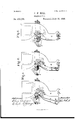
In the accompanying drawings, Figure 1 is an elevation of a grain weigher or scale containing my present improvement; Fig. 2, an elevation of the front end or side of grainspout. Figs. 3, 4, and 5 are end elevations of a portion of the grain-spout, and of the devices for operating the grain-valves.
Similar letters of reference indicate similar parts.
A is the frame of scale or weigher, B, the balance-beam; O, the suspenders, one on each side of grain-bucket D; E, the weight balancing the empty bucket; E, the grain-weight; F, the supplemental beam; F, the supplemental weight; F the poising-weight; G, the grainspout; H, the main valve, which (as fully eX- plained in several of the Letters Patent re i'erred to) first closes under the grain-spoutG and reduces the opening thereof to the smallest convenient aperture (in width) through which the grain being weighed will certainly run; H, the supplemental valve, which finally passes under the grain-spout and forms a posi tive cut-off of the flow of grain through spout G to bucket D.
d is a sector secured .to the ends of bucket D, with which a latch, c, pivoted to an arm on suspender O, engages to retain the bucket D in position to receive grain from spout G.
a is a detentone on each side of machine secured to side frame, A, which arreststhe descent of latch c and raises it clear of holdingcontact with sector cl, permitting the bucket -D to swing or oscillate onits bearings and dis charge the weighed grain from one compartment, while presenting the opposite compartment under the grain-spout for the next suc- ,ceeding load.
The devices already described are fully shown and explained in the former Letters.
Patent referred to, and need not further be alluded to, excepting such as are material to a description of the operation of the present improvemcnt.
Referring to Fig. 2, ct seq, J is the customary valve-shaft mounted in bearin gs G G upon the spout G, upon which shaft are hung the valves H H by arms h h, and actuated by a system of fixed and loose clutches, 7L2 h, as shown in Fig. 2. The clutches 7r swing-loose on shaft J; but the clutches h are secured rigidly to the shaft.
Upon both ends of shaft J are secured toes K, the upper ends of which form liftingtoes, and the lower ends form holdingtoes; or the lifting-toe and holding-toe may each be of a separate piece and independently secured to valve-shaft J; but I prefer to make the two toes in one piece, as shown, constructing the end K as a lifting-toe and the end I as a holding-toe. The arcs of motion oftlie toes K, K or K, and of the supplemental valve H, are the same, and as the toes K and arm h of supplemental valve II are rigidly secured to valve-shaft J, it follows that the angular motion of both is simultaneous and equal.
L are gravity-pawls pivoted one on each side of beam 13, at Z, and striking against stops Z) upon the beam M are stops secured to the beam B by serewsm. These stops maybe adjustable, if desired.
The toes K, K", pawls L, and stops M constitute thevalve-operating mechanism. The pawls L and lifting-toes K open the valves 11 H upon the rise of the beam 15, the point of pawl L passing above and clear of the point of toe K, as shown in Fig. 3, when the valves II II and toes K K gravitate downward through their are of motion until arrested by contact of holding-toe K with the stop M, same figure. Directly the major part of the load ofgrain is taken into bucket D, the bucket and beam B descend until the supplemental weight F rests upon the beam. Meanwhile the stop M has descended with the beam until the holding-toe is released, when the valves H II swing under the spout G, and the projection It onholding-toelT strikcs against the stop M, as shown in Fig. 4. During this movement the main valve II has closed against the stops 9 on spout G. Directly theiinal quantity of grain is taken into the bucket D, the bucket and beam 13, and consequently the stops M, descend lower, releasing the holding-toe K and permitting it to gravitate to the position shown in Fig. 5, and the supplemental valve II to close under the spout G. During the descent of the beam 13 the pawl L has drawn over the point of lifting-toe K, as shown in Fig. 5, in position to roll the toe upward into the position shown in Fig. 3, when the bucket D and beam 13 rise. The pawls L and toes K K are in duplicate upon opposite sides of machine, to insure greater certainty in the action of the mechanism; but one set of these elements is sufficient for the described purpose. The pawl L an d toes K K may take various forms; but those which I have shown are the simplest and cheapest of construction, and from experience the most reliable in operation.
I have shown and described my present invention as part of an automatic weigher containing two valves, one for the partial suppression of the stream from spout G, and the other for the final and complete cutoff; but I do not wish to limit it to a weigher having two valves, for it is just as applicable and useful to a machine with a single valve, as shown in my original patent of April 15, 1873, (reissued May 25, 1880.) In the latter case, however, the projection 7. 011 holdingtoe K would be omitted; otherwise the devices would be constructed and operated as shown and described.
It is obvious that the described devices will be as applicable to'nmchincs for weighing other commodities as for the weighing of grain.
Having described my invention, what I claim is 1. In an automatic weigher, a valve-open ating mechanism consisting of a pawl, L, mounted upon the scale-beam, lifting-toe K, and ho1ding-toe K, secured to the valve-shaft, and stop M, secured to the scale-beam, when arranged and operating substantially as dcscribed.
2. In combination with the scale-beam 1 and valveshal't J of an automatic weigher, the gravity-pawl L, pivoted to the scale-beam, and the lifting-toe K, secured to the valve shaft, for the purpose of imparting an upward rolling motion to the said shaft upon the rise of the scale-beam, substantially as described.
3. In combination with the scale beam I3 and valve-shaft J of an automatic weigher, the stop M, secured to the scale-bean1, and the holding-toe K, secured to the val ve-shaft, for the purpose of regulating the downward rolling motion of said shalt during the dcscent of the Sealebeam, substantially as described.
4. In combination with the scalebeam B and valveshal't J of an automatic weigher, a gravity-pawl, L, pivoted to the scale-beam, and a lifting-toe, K, secured to the valveshaft, so arranged and operating with relation to each other that upon the descent of the scale-beam the pawl engages with the lifting toe automatically, and upon the rise of the scale-beam the pawl raises the lilting-toe through its full are of motion and passes clear of said toe, substantiallv as described.
In testimony whereof I have signed my name to the foregoing specification in the presence of two subscribing witnesses.
JOHN \V. HILL.
IVitnesses:
Guns. Annnnsoiv, CHARLES S. Gili moun.
ITS
Publications (1)
| Publication Number | Publication Date |
|---|---|
| US302136A true US302136A (en) | 1884-07-15 |
Family
ID=2371309
Family Applications (1)
| Application Number | Title | Priority Date | Filing Date |
|---|---|---|---|
| US302136D Expired - Lifetime US302136A (en) | Grain-meter |
Country Status (1)
| Country | Link |
|---|---|
| US (1) | US302136A (en) |
-
0
- US US302136D patent/US302136A/en not_active Expired - Lifetime
Similar Documents
| Publication | Publication Date | Title |
|---|---|---|
| US302136A (en) | Grain-meter | |
| US554029A (en) | Automatic weighing-machine | |
| US694222A (en) | Weighing-machine. | |
| US632284A (en) | Automatic weighing-machine. | |
| US41906A (en) | Improvement in grain-weighers | |
| US490710A (en) | Charles j | |
| US214953A (en) | Improvement in grain-meters | |
| US403988A (en) | H- cooley | |
| US994265A (en) | Grain-weighing scale. | |
| US585785A (en) | reisert | |
| US548855A (en) | thompson | |
| US409702A (en) | Caster | |
| US607461A (en) | Automatic weighing-machine | |
| US413322A (en) | Stacy b | |
| US746200A (en) | Automatic weighing-machine. | |
| US600038A (en) | Weighing-machine | |
| US615196A (en) | Automatic weighing-machine | |
| US585970A (en) | Weighing-machine | |
| US421912A (en) | Automatic grain-scales | |
| US600035A (en) | Automatic weighing-machine | |
| US377606A (en) | Automatic grain-scale | |
| US505769A (en) | Jacob c | |
| US465535A (en) | Automatic grain-scale | |
| US1300313A (en) | Weigher. | |
| US585979A (en) | Automatic weighing-machine |