US3014591A - Laundry machine - Google Patents
Laundry machine Download PDFInfo
- Publication number
- US3014591A US3014591A US767717A US76771758A US3014591A US 3014591 A US3014591 A US 3014591A US 767717 A US767717 A US 767717A US 76771758 A US76771758 A US 76771758A US 3014591 A US3014591 A US 3014591A
- Authority
- US
- United States
- Prior art keywords
- speed
- basket
- machine
- clothes
- sheave
- Prior art date
- Legal status (The legal status is an assumption and is not a legal conclusion. Google has not performed a legal analysis and makes no representation as to the accuracy of the status listed.)
- Expired - Lifetime
Links
- XLYOFNOQVPJJNP-UHFFFAOYSA-N water Substances O XLYOFNOQVPJJNP-UHFFFAOYSA-N 0.000 description 26
- 238000005406 washing Methods 0.000 description 18
- 230000033001 locomotion Effects 0.000 description 14
- 239000004020 conductor Substances 0.000 description 10
- 238000001035 drying Methods 0.000 description 9
- 230000000694 effects Effects 0.000 description 9
- 238000000605 extraction Methods 0.000 description 8
- 239000007788 liquid Substances 0.000 description 8
- 230000007246 mechanism Effects 0.000 description 7
- 238000010438 heat treatment Methods 0.000 description 5
- 230000001133 acceleration Effects 0.000 description 4
- 230000009471 action Effects 0.000 description 4
- 230000007423 decrease Effects 0.000 description 4
- 230000002411 adverse Effects 0.000 description 3
- 238000010276 construction Methods 0.000 description 3
- 238000010981 drying operation Methods 0.000 description 3
- 239000004575 stone Substances 0.000 description 3
- 230000003247 decreasing effect Effects 0.000 description 2
- 230000000994 depressogenic effect Effects 0.000 description 2
- 238000012986 modification Methods 0.000 description 2
- 230000004048 modification Effects 0.000 description 2
- 230000004044 response Effects 0.000 description 2
- 238000013459 approach Methods 0.000 description 1
- 238000005452 bending Methods 0.000 description 1
- 230000005540 biological transmission Effects 0.000 description 1
- 230000008859 change Effects 0.000 description 1
- 150000001875 compounds Chemical class 0.000 description 1
- 230000001419 dependent effect Effects 0.000 description 1
- 239000004744 fabric Substances 0.000 description 1
- CPLXHLVBOLITMK-UHFFFAOYSA-N magnesium oxide Inorganic materials [Mg]=O CPLXHLVBOLITMK-UHFFFAOYSA-N 0.000 description 1
- 239000000395 magnesium oxide Substances 0.000 description 1
- AXZKOIWUVFPNLO-UHFFFAOYSA-N magnesium;oxygen(2-) Chemical compound [O-2].[Mg+2] AXZKOIWUVFPNLO-UHFFFAOYSA-N 0.000 description 1
- 238000000034 method Methods 0.000 description 1
- 230000005012 migration Effects 0.000 description 1
- 238000013508 migration Methods 0.000 description 1
- 230000005855 radiation Effects 0.000 description 1
- 230000009467 reduction Effects 0.000 description 1
Images


Classifications
-
- D—TEXTILES; PAPER
- D06—TREATMENT OF TEXTILES OR THE LIKE; LAUNDERING; FLEXIBLE MATERIALS NOT OTHERWISE PROVIDED FOR
- D06F—LAUNDERING, DRYING, IRONING, PRESSING OR FOLDING TEXTILE ARTICLES
- D06F34/00—Details of control systems for washing machines, washer-dryers or laundry dryers
- D06F34/14—Arrangements for detecting or measuring specific parameters
- D06F34/16—Imbalance
-
- D—TEXTILES; PAPER
- D06—TREATMENT OF TEXTILES OR THE LIKE; LAUNDERING; FLEXIBLE MATERIALS NOT OTHERWISE PROVIDED FOR
- D06F—LAUNDERING, DRYING, IRONING, PRESSING OR FOLDING TEXTILE ARTICLES
- D06F33/00—Control of operations performed in washing machines or washer-dryers
- D06F33/30—Control of washing machines characterised by the purpose or target of the control
- D06F33/48—Preventing or reducing imbalance or noise
-
- D—TEXTILES; PAPER
- D06—TREATMENT OF TEXTILES OR THE LIKE; LAUNDERING; FLEXIBLE MATERIALS NOT OTHERWISE PROVIDED FOR
- D06F—LAUNDERING, DRYING, IRONING, PRESSING OR FOLDING TEXTILE ARTICLES
- D06F2103/00—Parameters monitored or detected for the control of domestic laundry washing machines, washer-dryers or laundry dryers
- D06F2103/26—Imbalance; Noise level
Definitions
- This invention relates to laundry machines of the type which provide a centrifugal extraction of liquid from clothes, and more particularly to such machines which incorporate vibration sensitive arrangements for preventing operation at speeds capable of causing vibrations harmful to the machine.
- Laundry machines of the type generally provided for domestic use frequently include a centrifugal extraction of liquid from washed clothes by rotating the clothes receptacle or basket at high speed. In most cases the washing of the clothes is provided in the same machine, using the same receptacle as that in which the clothes are contained during the centrifugal liquid extraction step.
- washing machines of the type which provide a clothes basket rotatable on a vertical axis
- some type of washing means movable independently of the hasket positioned within the basket for the washing and rinsing operation, and the basket itself is rotated at high speed for the centrifugal liquid extraction
- the type of Washing machine which provides the clothes basket rotatable on a non-vertical (usually horizontal) axis
- the usual procedure is to effect the washing and rinsing operation by rotating the basket at an appropriate speed to make the clothes proceed in a tumbling pattern within the basket, and then rotating the basket at high speed to extract the liquid from the clothes.
- those domestic laundry machines generally of the non-vertical axis type, which combine the washing and centrifugal extraction steps with a heat drying step subsequent to the spin operation.
- any unbalance present during the high speed centrifugal extraction operation tends to cause undesirable vibration of the machine and consequent strain on the various parts of the machine, as well as a possible walking of the machine, i.e., movement of the machine across the floor.
- a further object of the invention is to achieve such a result by providing at least one intermediate speed below the normally provided centrifuging speed at which the transmission may operate if the vibrations are too. severe to permit the regular centrifuging speed to be attained without adverse effect.
- Another object of the invention is to provide for a spin operation at the maximum allowable speed after an acceptable minimum speed is reached, with a redistribution of the clothes being provided if the unbalance is sensed below the acceptable minimum speed
- Yet a further object of the invention is to provide an improved laundry machine which provides a predetermined maximum number for the attempts at balanced clothes redistribution, and then provides centrifuging at the maximum allowable speed.
- a laun-. dry machine which includes a rotatable clothes basket with suitable drive means for rotating the basket.
- the drive means is formed so as to accelerate the basket toward a maximum centrifuging speed in the usual manner; the drive means is also formed, according to our inven-. tion, so as to operate the basket at at least one intermediate centrifuging speed in addition to the usual maximum centrifuging speed.
- we provide means for sensing vibrations of the basket which result usually from unbalanced distribution of the clothes therewithin, and means responsive to the sensing of vibrations of the predetermined magnitude to stop acceleration of the basket and provide operation thereof at an intermediate centrifuging speed.
- FIGURE 1 is a front elevational view of a laundry machine, specifically a combination washerdryer, of the type which may incorporate my improved speed control arrangement;
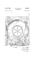
- FIGURE 2 is a rear elevational view of the combination washer-dryer, with the rear panel removedand with tion washer-dryer, partly in section and with certain surfaces broken away to show details;
- FIGURE 4 is a fragmentary view in cross section along line 44 in FIGURE 2, with the clothes basket and tub of the machine removed in order to illustrate details of the drive of the machine;
- FIGURE is an enlarged fragmentary plan view of a portion of the control mechanism shown in FIGURE 4;
- FIGURE 6 is a view along line 66 in FIGURE. 5;
- FIGURE 7 is a schematic illustration depicting a circuit which incorporates our invention.
- FIGURE 8 is an enlarged front elevational view of the vibration sensing arrangement provided as a component of our inventive combination.
- FIGURES l, 2 and 3 of the drawings there is shown, by way of illustration, a combination clothes washing and drying machine.
- the invention is not restricted to this particular type of laundry machine; however, the invention finds particular application in this type of machine because it usually provided a clothes basket rotatable on a generally horizontal axis, and because the inclusion of components from both washing and drying machines puts space at a high premium, i.e., the clearances between operating parts are small and there is consequently only a small leeway for vibrations.
- Section 1 is supported on a base and toe-board assembly 2 and carries a separate top 3 on which is supported a backsplash panel 4 which may, as shown, be mounted on posts 5.
- Control panel 4 is provided with appropriate control devices such as, for instance, dials 6 which may be provided for controlling various types of washing and drying sequences, and various drying temperatures, and such as buttons 7 which may control various other functions, such as water temperature, omission of dryer function, etc.
- the machine is of the horizontal type, that is, it has a substantially cylindrical clothes basket or receptacle 10 mounted for rotation on a generally horizontal axis within an outer enclosing tub structure 11.
- Basket 10 comprises a cylindrical shell or wall 12 which is closed at its rear end by means of a suitable wall or plate 13.
- the basket also includes a front wall 14 which is formed so as to define an access or loading opening 15 in registry with an opening 16 in wrap-around section 1 provided for door 8.
- the basket is rotatably supported by a shaft 17 which is mounted in an elongated bearing 18 supported from rear wall 19 of tub 11.
- the tub is also provided with an opening 20 aligned with opening 16 and opening 15 so that clothes may be placed into and removed from the basket when door 8 is opened.
- the door seals against a suitable gasket 21 during operation of the machine.
- the drive from the motor to the basket includes a pulley 23 which is secured to the motor. shaft so as to rotate therewith and over which passes a belt 24 driving an adjustable sheave assembly 25.
- the adjustable sheave assembly includes a shaft 26 to which are rigidly securedtwo sheave plates 27 and 28; an intermediate sheave plate 29 is keyed on shaft 26 so as to be movable along the shaft to varying distances from plates 27 and 28. It will be observed (FIGURE 3) that sheave plate 27 has a sloping surface 30 which, in cooperation with a sloping surface 31 on movable sheave plate 29, forms a groove 32 of adjustable width.
- movable sheave plate 29 is provided with a sloping surface 33 which cooperates with a sloping surface 34 on rigidly secured sheave plate 28 to form a second groove 35 of adjustable width. Since belt 24 has a predetermined width, it can be seen that movement of sheave plate 29 relative to sheave plate 27 will cause the belt 24 to seat in groove 32 at a distance from the center of shaft 26 which is determined by the distance of sheave plate 29 from sheave plate 27.
- the linear speed of belt 24 is constant, assuming the speed of motor 22 to be substantially constant, and therefore the rotation speed of the adjustable sheave assembly 25 is dependent on the effective sheave diameter provided by the cooperation of sheave plates 27 and 29.
- sheave assembly 25 is rotating at a relatively low speed. If sheave plate 29 is moved to the left as viewed in FIGURE 3, away from sheave plate 27, then belt 24 will move in radially toward shaft 26 as groove 32 widens, and will cause a greater rotational speed of the sheave assembly 25 for a given rotational speed of pulley 23 by motor 22.
- a second belt 36 is driven in groove 35 by the sheave formed by the cooperation of sheave plates 29 and 28.
- belt 36 has to move in radially toward shaft 26 a substantial amount before it seats on the surfaces 33 and 34 of sheave plates 29 and 28 respectively. This means that for a given rotational speed of the adjustable sheave assembly (as imparted to it by belt 24), belt 35 will be travelling at a relatively low rate of linear speed. If sheave plate 29 is moved to the left so that belt 36 is forced outwardly in groove 35, then for a given rotational speed of the sheave assembly a relatively high linear speed of belt 36 is provided.
- Belt 36 passes over a sheave 37 which forms part of a unitary assembly with a sheave 38 which drives the belt 39.
- belt 39 drives a sheave or pulley 40 which is rigidly secured to the end of shaft 17 so as to rotate basket 10.
- adjustable sheave assembly 25 is mounted on an arm 41 which is pivotably secured on a pin 42 within a bracket 43 secured to the base 2 of the machine.
- a spring 44 has one end 45 secured to the machine base and has its other end 46 secured to an arm 47, also secured to assembly 25, so as to bias it to the left.
- chain member 49 At the outer end 48 of arm 47 there is secured a chain member 49.
- chain member 49 At its other end (FIGURE 4), chain member 49 is secured to a pulley 50 operated through a small electric motor and gear train assembly 51. It will be seen that when pulley 50 is caused to rotate by assembly 51 it will wind up chain 49, and through arm 47 pull the entire adjustable sheave assembly to the right.
- the assembly of sheaves 37 and 38 is also movably mounted on a linkage arrangement 52 pivotably secured on a pin 53 mounted within a bracket 54 secured to the base.
- the linkage arrangement includes two arms 55 and 56 which are pivotably secured together through a pin 57.
- a spring 58 secured at one end, 59 to the base 2 of the machine is secured at its other end 60 to the assembly of sheaves 37 and 38 so as to bias them downwardly and to the right as viewed in FIGUREZ in order to effect a belt tensioning function for the belts 36 and 39.
- the proportioning of the various parts of the drive assembly above described is such as to provide an appropriate range of speeds. For instance, when the parts are in their position shown, a tumbling speed of approximately 47 rpm. is provided to the basket 10 while in the other extreme position a centrifuging speed of approximately 350 rpm. is provided to the basket.
- Machines of the type illustrated generally include appropriate means to heat the clothes during the drying portion of the cycle, and also to warm the wash water during the washing portion of the cycle when so desired.
- a heater assembly including two heaters 61 and 62. These heaters are mounted within the upper portion of tub 11 so that when energized they heat basket 10.
- the heating elements are preferably of the sheathed type in which a resistance wire is maintained in spaced relation with a sheath by a highly compressed granulated heat-conducting electrically-insulating compound such as magnesium oxide.
- the rotating basket serves as an active heat trans.- fer means between the heating element and the water or other washing liquid.
- the heaters When the heaters are energized during the drying cycle, the heat transferred to the clothes basket is then passed on to the clothes to cause vapor migration out of the clothes. Since the outer cylindrical wall of the basket is perforated by a great many small spaced openings 63 (FIGURE 3) some of the heat from the heating elements passes directly to the clothes by radiation.
- the means whereby water is admitted to and discharged from the tub 11 during operation of the machine isparticularly shown in FIGURE 2.
- the water supply means includes connections 64 and 65 through which hot and cold water is supplied to the machine forthe washing operation.
- a valve controlled by a solenoid 66 admits hot water to the machine and a valve controlled by an opposed solenoid 67 admits cold water to the machine.
- the hot and cold water valves. under the control of the solenoids 66 and 67. discharge through a common outlet conduit 68, through a suitable air gap, and then into a funnel 69 to a sump 70 formed at the bottom of tub 11.
- connection may be made through a suitable conduit 71, a portion of which is shown adjacent the sump in FIG- URE 2.
- the air gap provided by the funnel 69 makes it impossible for the water to be syphoned from the machine and to contaminate the incoming water supply line.
- a pressure actuated sensing device or water level control 72 controls both solenoids 66 and 67 to maintain the proper water level in the machine during the washing operation. Sensing device 72 is connected to the interior of tub 11 by a suitable line 74.
- the illustrated machine is of the type which uses cold water during the drying cycle for condensing the moisture extracted from the clothes. admitted tothe machine through an additional solenoid actuated valve controlled by a solenoid 75 which is energized during the drying operation so that the valve passes water at a slow rate sufficient to condense from the air the moisture vaporized from the clothes. As shown, the condenser water valve discharges into a conduit 76.
- vent trap 78 The condenser water is which is of the type commonly provided in connection with machines of this type in order to seal up the tub and basket from atmosphere during the heat drying of the clothes while leaving the tub vented to atmosphere at other times.
- An appropriate construction for vent trap 78 is, for instance, fully described and claimed in Patent 2,800,008Raczynski, issued on July 23, 1957 and assigned to the General Electric Company, owner of the present invention.
- the condenser water flows into the tub 11 through an opening 79 and then flows in a thin sheet down the lower left wall 80 of the tub (FIGURE 2) so as to cool a substantial portion of the area of the side wall and provide a large cool surface for condensing the moisture extracted from the clothes.
- a suitable discharge hose 81 leads from the sump to a motor driven drain pump 82 which may, as shown in FIGURE 4, be driven directly' from motor 22 and which discharges through an outlet 83 to a conduit 84 (FIGURE 2)'leading to a drain valve 85 controlled by an appropriate solenoid (not shown). Since pump 82 is continuously operated by motor 22, the draining of water from the sump 70 is controlled by the drain valve, draining occurring upon energization of the solenoid associated with the drain valve.
- tub 11 is supported from base 2 by means of a plurality of brackets or arms 86 which are mounted on upstanding plates 87 fixedly attached to the base. Four of these arms are provided, two being secured to each 1 side of the tub. The arms on the opposite sides of the near its front and near its rear on each side thereof.
- the arms 86 can be secured directly to the wall of tub 11, preferably, and as shown, the arms 86 are attached thereto by means of suitable brackets 88. With the tub 11 supported in the manner shown, it is able to vibrate sideways in a plane parallel to the front of the machine if the basket 10 should be unbalanced during a high speed rotation thereof.
- the arms 86 are relatively long compared to their width, and they flex so as to allow slight sideways vibration of the tub relative to the base 2. However, the arms are effective substantially to prevent vibration of the tub both from front to rear and in the vertical direction since they are not at all flexible in these directions.
- the sensing means may be conventionally formed to include a depending bracket 89 secured to the tub 11 as shown in FIGURES 1 and 8.
- the bracket being secured to the tub 11 and therefore to' the moving system mounted on arms 86, is movable in response to vibration caused by unbalances within the rotating basket 10.
- the bracket causes actuation of a button 90 of a switch 91 to cause an appropriate control sequence as explained herebelow.
- a suitable transmitting means is interposed between the bracket 89 and button 90 of switch 91.
- Motion transmitting means 92 includes an 7 tub. This motion transmitting construction is fully described and illustrated in Patent 2,832,208Stone, issued on April 29, 1958 and assigned to the General Electric Company, owner of the present invention.
- Actuation of button 90 causes energization of an auxiliary timer motor 96 (as will be further described, as to circuitry, in connection with FIGURE 7) which drives a star wheel 97 through suitable reduction gear means (not shown).
- the star wheel 97 rotates counterclockwise, as viewed in FIGURES 1 and 8, and is adapted to engage the upper end of a leaf spring 98 which is fixedly mounted at its lower end on the switch mounting bracket. As the star wheel 97 rotates, it bends the upper end of the leaf spring 98 to the right; this bending of the spring continues until such time as the spring is bent far enough for the engaging arm of the star wheel to slip over its top. At that time the spring snaps in the opposite direction, striking button 99 of switch 91 to cause de-energization of motor 96.
- bracket 89 transmits its motion through scissors members 93 and 94 to actuate button 90 of switch 91.
- this de-energizes motor 51 so that spring 44 pulls adjustable sheave assembly 25 back to the position shown in the figures so that a redistribution of the clothes occurs at tumble speed.
- auxiliary motor 96 is rotating star wheel 97 so that after an appropriate period, generally in the vicinity of 20 seconds, the star wheel will cause the spring member 98 to actuate button 99 of switch 91.
- this re-energizes motor 51 and thus the drive accelerates the basket once again towards maximum spin speed.
- a linkage member 100 has at its outer end an elongated slot 101 into which extends a pin 102 formed as part of arm 41.
- pin 102 When adjustable sheave assembly 25 is moved to the right by energization of motor 51 pin 102 will, after a small amount of such movement, engage the end of slot 101 and start to push the member 100 to the right, as viewed in FIGURE 2 (to the left in FIGURE 6).
- Linkage member 100 is pivotably secured by a pin 103 to a plate 104 of an assembly generally indicated at 105 which is pivotably mounted by a pin 106 to a bracket 107 secured to base 2. It will readily be seen that motion of link member 100 as described causes clockwise motion of assembly 105 about pin- 106 as viewed in FIGURE 2 (counterclockwise as viewed in FIGURE 6).
- a ratchet member 108 is slidably and pivotably mounted on member 104 by means of a pin 109 extending from member 104 through a slot 110 formed in the ratchet member 108.
- Ratchet wheel 111 has enough friction in sliding on member 104 to prevent relative motion except as actuated by the ratchet member 108.
- a member 112 having a switch actuating portion 113 is secured to move counterclockwise with ratchet wheel 111 as the assembly 105 is pivoted around.
- Actuating part 113 engages an arm member 114 which presses in the button 115 of a switch indicated generally at 115.
- the sheave assembly 25 has to be moved substantially its full extent to the right (as viewed in FIGURE 2).
- the assembly 105 When the assembly 25 is in tumble speed position, the assembly 105 is so arranged that the end of the ratchet 108 comes into engagement with a flange 117 formed on bracket 107. Each time the assembly 105 returns completely to its tumble position, flange 117 causes the ratchet 108 to be pushed against the action of spring a, with pin 109, sliding in slot 110. Because of the engagement of the ratchet 108 with the teeth of the ratchet wheel, and because the length of slot 110 is such as to allow ratchet 108 to move slightly more than the width of one tooth, this causes the ratchet wheel to be pushed around the width of one ratchet tooth relative to member 104. Clutch arrangement 117a secures member 112 to ratchet wheel 111 for counterclockwise movement of the ratchet wheel so that the movement of the wheel by ratchet 108 carries member 112 with it.
- a solenoid member is mounted on the base 2 and is pivotably connected by a pin 119 and extending arm 120, which are secured to movable core 121, to the member 112 carrying switch actuator 113.
- the solenoid When the solenoid is not energized, it of course has no effect on the operation of link member 100 and assembly 105, i.e., assembly 105 is completely under the control of link member 100.
- the solenoid 118 When the solenoid 118 is energized, it snaps the solenoid plunger 121 back into the solenoid, pulling with it arm 120. This exerts a clockwise pull on member 112; due to the action of friction clutch 117a, member 112 is then rotated relative to ratchet wheel 111 back to its starting position as shown in FIGURE 6. Ratchet wheel 111 is prevented from moving at this time as a result of the engagement of the teeth thereof with ratchet 108.
- Control 125 in addition to performing the functions specifically described in FIGURE 7, is also normally arranged to control the other electrical components of the machine including, for instance, a motor 22, solenoids 66, 67 and 75, heating elements 61 and 62, etc.
- control 125 has been omitted to retain as much clarity as possible in the specific features contributing to the applicants invention.
- a conductor 126 extends to switch 91 described in connection with the unbalance sensing arrangement of FIGURES 1 and 8.
- switch arm 127 of the switch is in the position shown, that is, in engagement with conductor 128.
- switch arm 127 moves down to a position where it engages contact 129.
- an energizing circuit is completed through conductor 130 to motor 51 to cause acceleration of the basket by movement of sheave assembly 25 to the right as viewed in FIGURE 2.
- the circuit for motor 51 is completed back to conduc'tor 124 through a conductor 131.
- switch arm 127 moves down into engagement with contact 129 (see FIGURE 6) a circuit is completed through a conductor 132, auxiliary timer motor 96 (FIGURE 1) and conductor 133, back to conductors 131 and 124.
- Switch 116 is in series with a solenoid 134 and a conductor 135, so that when the switch is open the solenoid coil is de-energized.
- motor 96 causes the de-energization of motor 51 to continue for a predetermined amount of time, generally on the order of 20 seconds, and then causes switch arm 127 to be moved back into engagement with contact 123.
- a circuit is completed through control 125- to cause energization of auxiliary motor 51 to accelerate the basket. If the unbalance sensing means indicates that the vibrations are excessive at any time, switch arm 127 is moved from the position shown into engagement with contact 129.
- switch 116 With switch 116 open, this provides, under control of motor 96, a period of redistribution and then again energizes motor 51 for another attempt at spin speed.
- the open position of switch 116 to start with is insured by causing the solenoid 118 to be energized prior to each spin operation; as explained in connection with FIGURE 6, this energization of solenoid 118 returns the member 112 to a position where actuator 113.has a maximum distance to travel before switch 116 is closed. That is, switch 116 does not become closed until approximately the maximum spin speed provided by the machine.
- the solenoid 118 is de-energized, its sole function being to return the actuating member 113 to its initial position for the commencement of each spin cycle.
- each attempt at redistribution causes actuator 113- to move closer to member 114 so that less travel of sheave assembly 125 is necessary before the switch 116 is closed.
- the larger the number of unsuccessfulredistribution attempts the lower the speed at which the switch 116 closes.
- the switch will be closed as soon as assembly 25 moves sufiiciently to effect, through linkage member 100, any movement of actuator 113.
- the mechanism of FIGURES 5 and 6 is in effect a counting device, providing certain closing of switch 116 after a predetermined number of balancing attempts.
- an indication that the clothes load is not of the easiest kind to balance is used to provide a decrease in the minimum speed at which the spin operation may be conducted.
- a second operation of the unbalance mechanism will decrease the minimum permissible spin speed a like amount further, and so on until the speed is finally decreased to the extent where, even though the type of clothes load may be one where the unbalance is continually severe, a spin operation will be provided at the maximum speed which is possible Without causing damage to the machine, or walking of the machine.
- a laundry machine including a rotatable clothes basket, drive means for rotating said basket, said drive means being formed to accelerate said basket toward a maximum centrifuging speed and being also formed to operate said basket at at least one intermediate centrifuging speed, sequence control means causing said drive means to provide a centrifuging speed to said basket for a predetermined centrifuging cycle means for sensing vibrations of said basket resulting from unbalanced distribution of the clothes therewithin during centrifuging thereof, and means responsive to sensing of vibrations of a predetermined magnitude to stop acceleration of said basket and provide operation continuously at an intermediate centrifuging speed for the remainder of said centrifuging cycle.
- a laundry machine including a rotatable clothes basket, drive means for rotating said basket, said drive means including a variable speed belt drive comprising a belt and a pair of rotatable sheave plates forming a groove between them, at least one of said sheave plates being axially movable relative to the other thereby to vary the distance from the center of rotation thereof at which said belt seats in said groove so as to vary the output speed of said belt, means for moving at least one of said sheave plates relative to the other so as to accelerate said basket toward a maximum centrifuging speed, means for sensing vibrations of said basket resulting from unbalanced distribution of the clothes therewithin, and means responsive to sensing of vibrations of a predetermined magnitude to lock said sheave plates axially relative to each other thereby to provide operation thereof substantially at the speed at which said predetermined vibrations were sensed.
- a variable speed belt drive comprising a belt and a pair of rotatable sheave plates forming a groove between them, at least one of said shea
- a laundry machine including a rotatable clothes basket, drive means for rotating said basket including a variable speed belt drive comprising a pair of rotatable sheave plates forming a belt-receiving groove between them, at least one of said sheave plates being axially movable relative to the other thereby to vary the width of said groove, belt means seated within said groove at varying distances from the center of rotation of said sheave plates depending upon their axial position relative to each other, electric motor means for moving at least one of said sheave plates relative to the other to accelerate said basket toward a maximum centrifuging speed, means for sensing vibration of said basket resulting from unbalanced distribution of the clothes therewithin, switch means having first and second operative positions, said switch means having said first position prior to the sensing of vibrations of said predetermined magnitude, said sensing means moving said switch means to said second position thereof upon sensing vibrations of said predetermined magnitude, and means for locking said sheave plates axially relative to each other, said switch means being operative to energize
- said switch means being operative in said second position after an appropriate minimum centrifuging speed is reached to energize said locking means thereby to provide for a centrifuging operation at an intermediate spin speed.
- said locking means comprises cam means secured to said motor and having a plurality of recesses, and an electrically operated cam follower operative when seated in one of said recesses to lock said motor to provide a constant basket speed.
- a laundry machine including a rotatable clothes basket, drive means for rotating said basket, drive control means formed to accelerate said basket toward a maximum centrifuging speed, means for sensing vibrations of said basket resulting from unbalanced distribution of the clothes therewithin, means for slowing said clothes basket down for redistribution of the clothes therewithin when said predetermined magnitude of vibrations occurs, speed locking means for stopping acceleration of said basket and providing operation thereof at an intermediate centrifuging speed when said predetermined magnitude of vibrations is sensed, and speed responsive means for making said speed locking means operable and said slowing means inoperable as a predetermined minimum speed is reached.
- said speed responsive means comprises a switch member having two operative positions and movable from the first of said positions to the second of said positions at said predetermined minimum speed, said first position of said switch means permitting energizing of said slowing means upon operation of said sensing means, said second position of said switch means permitting energizing of said locking means upon operation of said sensing means.
Landscapes
- Engineering & Computer Science (AREA)
- Textile Engineering (AREA)
- Control Of Washing Machine And Dryer (AREA)
Description
Dec. 26, 1961 A. M. STONE ETAL 3,014,591
LAUNDRY MACHINE Filed Oct. 16, 1958 4 Sheets-Sheet 2 INVENTORS F-l AIDAN M. arena 5 JOSEPH c. WORST Y w P W THEIR ATTORNEY A. M. STONE ETAL 3,014,591
LAUNDRY MACHINE 4 Sheets-Sheet 3 Dec. 26, 1961 Filed Oct. 16, 1958 IN VEN TORS STONE WORST AIDAN M- 8 J'OSEPH B Qu 4W THEIR ATTORNEY \T.- 3 2 1 u r J 4 Lo 3 2 O0 00 M 0 O8 8 a 0 o v 0 n 2 v o 0 0 o 0 c I I J O a Q s P O 6/@( 6 8 8 o O 0 Km 08 l. u 0 00 "n 3,014,591 I LAUNDRY MACHINE Aidan M. Stone and Joseph C. Worst, Louisville, Ky., assignors to General Electric Company, a corporation of New York Filed Oct. 16, 1958, Ser. No. 767,717 7 Claims. (Cl. 210-444) This invention relates to laundry machines of the type which provide a centrifugal extraction of liquid from clothes, and more particularly to such machines which incorporate vibration sensitive arrangements for preventing operation at speeds capable of causing vibrations harmful to the machine.
Laundry machines of the type generally provided for domestic use frequently include a centrifugal extraction of liquid from washed clothes by rotating the clothes receptacle or basket at high speed. In most cases the washing of the clothes is provided in the same machine, using the same receptacle as that in which the clothes are contained during the centrifugal liquid extraction step. Such machines are generally of two main types: in washing machines of the type which provide a clothes basket rotatable on a vertical axis, there is generally provided some type of washing means movable independently of the hasket positioned within the basket for the washing and rinsing operation, and the basket itself is rotated at high speed for the centrifugal liquid extraction; in the type of Washing machine which provides the clothes basket rotatable on a non-vertical (usually horizontal) axis, the usual procedure is to effect the washing and rinsing operation by rotating the basket at an appropriate speed to make the clothes proceed in a tumbling pattern within the basket, and then rotating the basket at high speed to extract the liquid from the clothes. There are, of course, also those domestic laundry machines, generally of the non-vertical axis type, which combine the washing and centrifugal extraction steps with a heat drying step subsequent to the spin operation.
In machines which provide for washing and rinsing operations prior to the spin operation, and in those machines which provide a heat drying operation subsequent to the spin, the unbalances within the basket during such operations are so small as to be negligible. In vertical axis machines, there is normally no rotation of the basket at all during these operations, and in machines having a basket rotatable on a non-vertical axis the tumbling is generally conducted at speeds in the vicinity of 47 r.p.m. (the speed being a function of the basket diameter) where the vibrations are small and harmless. However, in both types of machines, any unbalance present during the high speed centrifugal extraction operation tends to cause undesirable vibration of the machine and consequent strain on the various parts of the machine, as well as a possible walking of the machine, i.e., movement of the machine across the floor. This is particularly true where the hasket is rotatable on a non-vertical axis, and, as is common, is supported in cantilever fashion at one end only.
To preclude the harm which may result from operation of the machine during the existence of the undesirable vibrations, most laundry machines of the general type described above are provided with unbalance mechanisms which may operate in a variety of ways to preclude harm to the machine through excessive vibration caused by high speed rotation with an unbalanced load in the basket. For instance, in some cases controls are actuated by the unbalance switch to return the clothes receptacle to its low speed for a brief period of time to give the clothes a chance to redistribute themselves, thereafter again attempting the high speed of rotation. Another alternative is simply to shut the machine off if an unbalance is sensed by the unbalance switch.
Patented Dec. 26, 1961 ice 2 In the first of the two foregoing pos'sible approaches, there is of course some degree of liquid removed, r'e= gardless of what happens. However, if the unbalance should be such that it continues to remain uncorrected throughout the time allotted'for the spin operation, the clothes will be exceedingly wet at'the end of the spin operation. If the machine is shut off completely, as in the second possibility set forth above, then of course the operator has to return to the machine and. start it up again. In addition to this, the second possibility is also open to the same objection as the first, that is, that the particular type of clothes load may preclude a distribution of the clothes good enough to permit the regular centrifuging speed to be attained even though several attempts be made.
It is therefore an object of the present invention to provide an improved laundry machine construction which insures some degree of centrifugal extraction regardless of continued poor distribution of the clothes in the basket.
A further object of the invention is to achieve such a result by providing at least one intermediate speed below the normally provided centrifuging speed at which the transmission may operate if the vibrations are too. severe to permit the regular centrifuging speed to be attained without adverse effect.
Another object of the invention is to provide for a spin operation at the maximum allowable speed after an acceptable minimum speed is reached, with a redistribution of the clothes being provided if the unbalance is sensed below the acceptable minimum speed Yet a further object of the invention is to provide an improved laundry machine which provides a predetermined maximum number for the attempts at balanced clothes redistribution, and then provides centrifuging at the maximum allowable speed.
In accordance with the invention, we provide a laun-. dry machine which includes a rotatable clothes basket with suitable drive means for rotating the basket. The drive means is formed so as to accelerate the basket toward a maximum centrifuging speed in the usual manner; the drive means is also formed, according to our inven-. tion, so as to operate the basket at at least one intermediate centrifuging speed in addition to the usual maximum centrifuging speed. In cooperation with the other parts of the machine, we provide means for sensing vibrations of the basket which result usually from unbalanced distribution of the clothes therewithin, and means responsive to the sensing of vibrations of the predetermined magnitude to stop acceleration of the basket and provide operation thereof at an intermediate centrifuging speed. other words, inability of the machine to distribute the clothes so that they are sufliciently balanced for the desirable highest possible centrifuging speed to be provided will cause a lower speed centrifuging spin action so that a substantial amount of liquid is removed from the cloth despite the unbalance. i
The subject matter which we regard as our invention is particularly pointed out and distinctly claimed in the concluding portion of this specification. Our invention itself, however, may best be understood by reference to the following description taken in conjunction with the accompanying drawings.
In the drawings, FIGURE 1 is a front elevational view of a laundry machine, specifically a combination washerdryer, of the type which may incorporate my improved speed control arrangement;
FIGURE 2 is a rear elevational view of the combination washer-dryer, with the rear panel removedand with tion washer-dryer, partly in section and with certain surfaces broken away to show details;
FIGURE 4 is a fragmentary view in cross section along line 44 in FIGURE 2, with the clothes basket and tub of the machine removed in order to illustrate details of the drive of the machine; I
FIGURE is an enlarged fragmentary plan view of a portion of the control mechanism shown in FIGURE 4;
FIGURE 6 is a view along line 66 in FIGURE. 5;
FIGURE 7 is a schematic illustration depicting a circuit which incorporates our invention; and
FIGURE 8 is an enlarged front elevational view of the vibration sensing arrangement provided as a component of our inventive combination.
Referring now to FIGURES l, 2 and 3 of the drawings, there is shown, by way of illustration, a combination clothes washing and drying machine. It will of course be understood that the invention is not restricted to this particular type of laundry machine; however, the invention finds particular application in this type of machine because it usually provided a clothes basket rotatable on a generally horizontal axis, and because the inclusion of components from both washing and drying machines puts space at a high premium, i.e., the clearances between operating parts are small and there is consequently only a small leeway for vibrations.
In the machine shown, the operating elements of the machine are included within an outer cabinet structure having a central wrap-around section 1. Section 1 is supported on a base and toe-board assembly 2 and carries a separate top 3 on which is supported a backsplash panel 4 which may, as shown, be mounted on posts 5. Control panel 4 is provided with appropriate control devices such as, for instance, dials 6 which may be provided for controlling various types of washing and drying sequences, and various drying temperatures, and such as buttons 7 which may control various other functions, such as water temperature, omission of dryer function, etc. Access to the interior of the machine is provided by a door 8 formed in section 1, mounted on concealed hinges and opened by means of a latch control 96 As best shown in FIGURE 3, the machine is of the horizontal type, that is, it has a substantially cylindrical clothes basket or receptacle 10 mounted for rotation on a generally horizontal axis within an outer enclosing tub structure 11. Basket 10 comprises a cylindrical shell or wall 12 which is closed at its rear end by means of a suitable wall or plate 13. The basket also includes a front wall 14 which is formed so as to define an access or loading opening 15 in registry with an opening 16 in wrap-around section 1 provided for door 8. The basket is rotatably supported by a shaft 17 which is mounted in an elongated bearing 18 supported from rear wall 19 of tub 11. The tub is also provided with an opening 20 aligned with opening 16 and opening 15 so that clothes may be placed into and removed from the basket when door 8 is opened. The door seals against a suitable gasket 21 during operation of the machine.
Referring now to FIGURES 2, 3 and 4, during the operation of the machine the basket 10 is driven from an electric motor 22. The drive from the motor to the basket includes a pulley 23 which is secured to the motor. shaft so as to rotate therewith and over which passes a belt 24 driving an adjustable sheave assembly 25. The adjustable sheave assembly includes a shaft 26 to which are rigidly securedtwo sheave plates 27 and 28; an intermediate sheave plate 29 is keyed on shaft 26 so as to be movable along the shaft to varying distances from plates 27 and 28. It will be observed (FIGURE 3) that sheave plate 27 has a sloping surface 30 which, in cooperation with a sloping surface 31 on movable sheave plate 29, forms a groove 32 of adjustable width. Similarly, on its other side movable sheave plate 29 is provided with a sloping surface 33 which cooperates with a sloping surface 34 on rigidly secured sheave plate 28 to form a second groove 35 of adjustable width. Since belt 24 has a predetermined width, it can be seen that movement of sheave plate 29 relative to sheave plate 27 will cause the belt 24 to seat in groove 32 at a distance from the center of shaft 26 which is determined by the distance of sheave plate 29 from sheave plate 27. The linear speed of belt 24 is constant, assuming the speed of motor 22 to be substantially constant, and therefore the rotation speed of the adjustable sheave assembly 25 is dependent on the effective sheave diameter provided by the cooperation of sheave plates 27 and 29. When the sheave plates 29 and 27 are in the position shown in the figures, sheave assembly 25 is rotating at a relatively low speed. If sheave plate 29 is moved to the left as viewed in FIGURE 3, away from sheave plate 27, then belt 24 will move in radially toward shaft 26 as groove 32 widens, and will cause a greater rotational speed of the sheave assembly 25 for a given rotational speed of pulley 23 by motor 22.
A second belt 36 is driven in groove 35 by the sheave formed by the cooperation of sheave plates 29 and 28. When adjustable sheave plate 29 is in the position shown so that groove 35 is quite wide, belt 36 has to move in radially toward shaft 26 a substantial amount before it seats on the surfaces 33 and 34 of sheave plates 29 and 28 respectively. This means that for a given rotational speed of the adjustable sheave assembly (as imparted to it by belt 24), belt 35 will be travelling at a relatively low rate of linear speed. If sheave plate 29 is moved to the left so that belt 36 is forced outwardly in groove 35, then for a given rotational speed of the sheave assembly a relatively high linear speed of belt 36 is provided. Thus, by controlling the position of sheave plate 29, an infinite variety of speeds between the two limits of position of the sheave plates may be provided, with the arrangement shown in FIGURE 3 providing the lowest output speed to belt 36, since belt 24 is causing the lowest rate of rotation of sheave assembly 25, and since rotation of. the sheave assembly 25 is causing the lowest linear speed of belt 36. The highest rate of speed will be provided as sheave plate 29 is moved as far as possible to the left, in which case belt 24 moves inwardly as far as possible to provide the highest rotational speed of the assembly 25 for a given linear speed of belt 24, and the output linear speed of belt 36 is the highest possible for a given rotational speed of assembly 25.
Returning now to the adjustable sheave assembly 25, and with particular reference to FIGURE 2, it will be observed that the assembly is mounted on an arm 41 which is pivotably secured on a pin 42 within a bracket 43 secured to the base 2 of the machine. A spring 44 has one end 45 secured to the machine base and has its other end 46 secured to an arm 47, also secured to assembly 25, so as to bias it to the left. At the outer end 48 of arm 47 there is secured a chain member 49. At its other end (FIGURE 4), chain member 49 is secured to a pulley 50 operated through a small electric motor and gear train assembly 51. It will be seen that when pulley 50 is caused to rotate by assembly 51 it will wind up chain 49, and through arm 47 pull the entire adjustable sheave assembly to the right. Since belt 24 cannot stretch it will be apparent that when this occurs belt 24 will move inwardly within groove 32 forcing sheave 29 to the left (as viewed in FIGURE 3) to effect an increase in the speed transmitted to pulley 40 and basket 10. When motor and gear train assembly 51 is shut off, the spring 44 overcomes the motor and pulls the adjustable sheave 25 back to the position shown in the figures to reduce the speed.
The assembly of sheaves 37 and 38 is also movably mounted on a linkage arrangement 52 pivotably secured on a pin 53 mounted within a bracket 54 secured to the base. The linkage arrangement includes two arms 55 and 56 which are pivotably secured together through a pin 57. A spring 58 secured at one end, 59 to the base 2 of the machine is secured at its other end 60 to the assembly of sheaves 37 and 38 so as to bias them downwardly and to the right as viewed in FIGUREZ in order to effect a belt tensioning function for the belts 36 and 39.
The proportioning of the various parts of the drive assembly above described is such as to provide an appropriate range of speeds. For instance, when the parts are in their position shown, a tumbling speed of approximately 47 rpm. is provided to the basket 10 while in the other extreme position a centrifuging speed of approximately 350 rpm. is provided to the basket.
Machines of the type illustrated generally include appropriate means to heat the clothes during the drying portion of the cycle, and also to warm the wash water during the washing portion of the cycle when so desired. To effect this function, there is provided in the machine a heater assembly including two heaters 61 and 62. These heaters are mounted within the upper portion of tub 11 so that when energized they heat basket 10. The heating elements are preferably of the sheathed type in which a resistance wire is maintained in spaced relation with a sheath by a highly compressed granulated heat-conducting electrically-insulating compound such as magnesium oxide. When the heaters are energized during the washing cycle, they heat the water by first heating the basket; then, as the basket dips into the wash water at the bottom of the tub, it in turn heats the water. In other words, the rotating basket serves as an active heat trans.- fer means between the heating element and the water or other washing liquid. When the heaters are energized during the drying cycle, the heat transferred to the clothes basket is then passed on to the clothes to cause vapor migration out of the clothes. Since the outer cylindrical wall of the basket is perforated by a great many small spaced openings 63 (FIGURE 3) some of the heat from the heating elements passes directly to the clothes by radiation.
The means whereby water is admitted to and discharged from the tub 11 during operation of the machine isparticularly shown in FIGURE 2. The water supply means includes connections 64 and 65 through which hot and cold water is supplied to the machine forthe washing operation. A valve controlled by a solenoid 66 admits hot water to the machine and a valve controlled by an opposed solenoid 67 admits cold water to the machine. The hot and cold water valves. under the control of the solenoids 66 and 67. discharge through a common outlet conduit 68, through a suitable air gap, and then into a funnel 69 to a sump 70 formed at the bottom of tub 11.
The connection may be made through a suitable conduit 71, a portion of which is shown adjacent the sump in FIG- URE 2. The air gap provided by the funnel 69 makes it impossible for the water to be syphoned from the machine and to contaminate the incoming water supply line. A pressure actuated sensing device or water level control 72 controls both solenoids 66 and 67 to maintain the proper water level in the machine during the washing operation. Sensing device 72 is connected to the interior of tub 11 by a suitable line 74.
The illustrated machine is of the type which uses cold water during the drying cycle for condensing the moisture extracted from the clothes. admitted tothe machine through an additional solenoid actuated valve controlled by a solenoid 75 which is energized during the drying operation so that the valve passes water at a slow rate sufficient to condense from the air the moisture vaporized from the clothes. As shown, the condenser water valve discharges into a conduit 76. From this conduit the water flows through an appropriate air gap (not shown) and then through another conduit (not shown) tothe inlet 77 of a vent trap 78 The condenser water is which is of the type commonly provided in connection with machines of this type in order to seal up the tub and basket from atmosphere during the heat drying of the clothes while leaving the tub vented to atmosphere at other times. An appropriate construction for vent trap 78 is, for instance, fully described and claimed in Patent 2,800,008Raczynski, issued on July 23, 1957 and assigned to the General Electric Company, owner of the present invention. From the vent trap 78, the condenser water flows into the tub 11 through an opening 79 and then flows in a thin sheet down the lower left wall 80 of the tub (FIGURE 2) so as to cool a substantial portion of the area of the side wall and provide a large cool surface for condensing the moisture extracted from the clothes.
The wash and rinse water used during the washing portion of the operation, and the condenser water and the moisture extracted from the clothes during the drying operation, are discharged from the machine through the sump 70 mounted at the bottom of the tub. A suitable discharge hose 81 leads from the sump to a motor driven drain pump 82 which may, as shown in FIGURE 4, be driven directly' from motor 22 and which discharges through an outlet 83 to a conduit 84 (FIGURE 2)'leading to a drain valve 85 controlled by an appropriate solenoid (not shown). Since pump 82 is continuously operated by motor 22, the draining of water from the sump 70 is controlled by the drain valve, draining occurring upon energization of the solenoid associated with the drain valve.
Referring now primarily to FIGURES 1 and 2 it will be observed that tub 11 is supported from base 2 by means of a plurality of brackets or arms 86 which are mounted on upstanding plates 87 fixedly attached to the base. Four of these arms are provided, two being secured to each 1 side of the tub. The arms on the opposite sides of the near its front and near its rear on each side thereof.
Although the arms 86 can be secured directly to the wall of tub 11, preferably, and as shown, the arms 86 are attached thereto by means of suitable brackets 88. With the tub 11 supported in the manner shown, it is able to vibrate sideways in a plane parallel to the front of the machine if the basket 10 should be unbalanced during a high speed rotation thereof. The arms 86 are relatively long compared to their width, and they flex so as to allow slight sideways vibration of the tub relative to the base 2. However, the arms are effective substantially to prevent vibration of the tub both from front to rear and in the vertical direction since they are not at all flexible in these directions.
Means are provided for sensing the amount of sideways vibration thereby' to prevent that vibration from ever becoming great enough to damage the machine, or to cause it to move on the floor. The sensing means may be conventionally formed to include a depending bracket 89 secured to the tub 11 as shown in FIGURES 1 and 8. The bracket, being secured to the tub 11 and therefore to' the moving system mounted on arms 86, is movable in response to vibration caused by unbalances within the rotating basket 10. When the magnitude of vibration of bracket 89 reaches a predetermined level, the bracket causes actuation of a button 90 of a switch 91 to cause an appropriate control sequence as explained herebelow.
A suitable transmitting means, generally indicated at 92', is interposed between the bracket 89 and button 90 of switch 91. Motion transmitting means 92 includes an 7 tub. This motion transmitting construction is fully described and illustrated in Patent 2,832,208Stone, issued on April 29, 1958 and assigned to the General Electric Company, owner of the present invention.
Actuation of button 90 causes energization of an auxiliary timer motor 96 (as will be further described, as to circuitry, in connection with FIGURE 7) which drives a star wheel 97 through suitable reduction gear means (not shown). The star wheel 97 rotates counterclockwise, as viewed in FIGURES 1 and 8, and is adapted to engage the upper end of a leaf spring 98 which is fixedly mounted at its lower end on the switch mounting bracket. As the star wheel 97 rotates, it bends the upper end of the leaf spring 98 to the right; this bending of the spring continues until such time as the spring is bent far enough for the engaging arm of the star wheel to slip over its top. At that time the spring snaps in the opposite direction, striking button 99 of switch 91 to cause de-energization of motor 96.
With the unbalance sensing arrangement described, when the unpredetermined magnitude of vibration is reached bracket 89 transmits its motion through scissors members 93 and 94 to actuate button 90 of switch 91. As will be more fully described herebelow in connection with the circuit of FIGURE 7, this de-energizes motor 51 so that spring 44 pulls adjustable sheave assembly 25 back to the position shown in the figures so that a redistribution of the clothes occurs at tumble speed. At the same time, as stated, auxiliary motor 96 is rotating star wheel 97 so that after an appropriate period, generally in the vicinity of 20 seconds, the star wheel will cause the spring member 98 to actuate button 99 of switch 91. In addition to de-energization of motor 96, this re-energizes motor 51 and thus the drive accelerates the basket once again towards maximum spin speed.
Referring now to FIGURES 2, and 6, a linkage member 100 has at its outer end an elongated slot 101 into which extends a pin 102 formed as part of arm 41. With this connection, when adjustable sheave assembly 25 is moved to the right by energization of motor 51 pin 102 will, after a small amount of such movement, engage the end of slot 101 and start to push the member 100 to the right, as viewed in FIGURE 2 (to the left in FIGURE 6). Linkage member 100 is pivotably secured by a pin 103 to a plate 104 of an assembly generally indicated at 105 which is pivotably mounted by a pin 106 to a bracket 107 secured to base 2. It will readily be seen that motion of link member 100 as described causes clockwise motion of assembly 105 about pin- 106 as viewed in FIGURE 2 (counterclockwise as viewed in FIGURE 6).
A ratchet member 108 is slidably and pivotably mounted on member 104 by means of a pin 109 extending from member 104 through a slot 110 formed in the ratchet member 108. A spring 110a secured between the ratchet member 108 and member 104 biases the ratchet member down into engagement with a ratchet Wheel 111. Ratchet wheel 111 has enough friction in sliding on member 104 to prevent relative motion except as actuated by the ratchet member 108. A member 112 having a switch actuating portion 113 is secured to move counterclockwise with ratchet wheel 111 as the assembly 105 is pivoted around. Actuating part 113 engages an arm member 114 which presses in the button 115 of a switch indicated generally at 115. In order for member 113 to cause depression of button 115 with the parts in the position shown, the sheave assembly 25 has to be moved substantially its full extent to the right (as viewed in FIGURE 2).
When the assembly 25 is in tumble speed position, the assembly 105 is so arranged that the end of the ratchet 108 comes into engagement with a flange 117 formed on bracket 107. Each time the assembly 105 returns completely to its tumble position, flange 117 causes the ratchet 108 to be pushed against the action of spring a, with pin 109, sliding in slot 110. Because of the engagement of the ratchet 108 with the teeth of the ratchet wheel, and because the length of slot 110 is such as to allow ratchet 108 to move slightly more than the width of one tooth, this causes the ratchet wheel to be pushed around the width of one ratchet tooth relative to member 104. Clutch arrangement 117a secures member 112 to ratchet wheel 111 for counterclockwise movement of the ratchet wheel so that the movement of the wheel by ratchet 108 carries member 112 with it.
This then has the result of moving actuating member 113 around toward member 114 a little, so that the assembly 105 does not have to rotate as much in a counterclockwise direction (as viewed in FIGURE 6) the next time before the switch button is depressed. In other words, every time there is an attempt at spin speed so that sheave assembly 25 causes link member 100 to rotate assembly 105 about pin 106, and the attempt fails because of unbalances so that the assembly is returned to its tumble position, ratchet 108 moves wheel 111 around one tooth and consequently member 113 has to travel that much less before there is actuation of button 115.
A solenoid member, generally indicated at 118, is mounted on the base 2 and is pivotably connected by a pin 119 and extending arm 120, which are secured to movable core 121, to the member 112 carrying switch actuator 113. When the solenoid is not energized, it of course has no effect on the operation of link member 100 and assembly 105, i.e., assembly 105 is completely under the control of link member 100. When the solenoid 118 is energized, it snaps the solenoid plunger 121 back into the solenoid, pulling with it arm 120. This exerts a clockwise pull on member 112; due to the action of friction clutch 117a, member 112 is then rotated relative to ratchet wheel 111 back to its starting position as shown in FIGURE 6. Ratchet wheel 111 is prevented from moving at this time as a result of the engagement of the teeth thereof with ratchet 108.
Having now explained the operation of the drive means ofthe machine, the operation of the vibration sensing mechanism, and the operation of the mechanism of FIG- URES 5 and 6, we will now describe the operation of the entire vibration controlling system, referring to FIG- URE 7.
Power is supplied to the components of the machine through a pair of conductors 123 and 124 which are connected in the usual manner across an appropriate source of alternating current power. Conductors 123 and 124 energize the components through a control 125 which may be of the conventional type, as well known in the art. It will be understood that control 125, in addition to performing the functions specifically described in FIGURE 7, is also normally arranged to control the other electrical components of the machine including, for instance, a motor 22, solenoids 66, 67 and 75, heating elements 61 and 62, etc. However, the connection and control of these components by control 125 has been omitted to retain as much clarity as possible in the specific features contributing to the applicants invention. From control 125, a conductor 126 extends to switch 91 described in connection with the unbalance sensing arrangement of FIGURES 1 and 8. After the button 99 of switch 91 has been depressed, switch arm 127 of the switch is in the position shown, that is, in engagement with conductor 128. When the button 90 of switch 91 is actuated, switch arm 127 moves down to a position where it engages contact 129. When the switch arm 127 engages contact 128, an energizing circuit is completed through conductor 130 to motor 51 to cause acceleration of the basket by movement of sheave assembly 25 to the right as viewed in FIGURE 2. The circuit for motor 51 is completed back to conduc'tor 124 through a conductor 131. When switch arm 127 moves down into engagement with contact 129 (see FIGURE 6) a circuit is completed through a conductor 132, auxiliary timer motor 96 (FIGURE 1) and conductor 133, back to conductors 131 and 124. Switch 116 is in series with a solenoid 134 and a conductor 135, so that when the switch is open the solenoid coil is de-energized.
The operation of motor 96 causes the de-energization of motor 51 to continue for a predetermined amount of time, generally on the order of 20 seconds, and then causes switch arm 127 to be moved back into engagement with contact 123. Thus, in effect, what occurs is that after the appropriate Washing, rinsing and draining operation, when the machine control 12 5 designates that the time is appropriate for spin, a circuit is completed through control 125- to cause energization of auxiliary motor 51 to accelerate the basket. If the unbalance sensing means indicates that the vibrations are excessive at any time, switch arm 127 is moved from the position shown into engagement with contact 129. With switch 116 open, this provides, under control of motor 96, a period of redistribution and then again energizes motor 51 for another attempt at spin speed. The open position of switch 116 to start with is insured by causing the solenoid 118 to be energized prior to each spin operation; as explained in connection with FIGURE 6, this energization of solenoid 118 returns the member 112 to a position where actuator 113.has a maximum distance to travel before switch 116 is closed. That is, switch 116 does not become closed until approximately the maximum spin speed provided by the machine. At all other times the solenoid 118 is de-energized, its sole function being to return the actuating member 113 to its initial position for the commencement of each spin cycle.
Each time there is an unbalancesuflicient to cause a deenergization of motor 51, redistribution of the clothes, and another attempt at high speed spin, the assembly 105 (FIGURE 6) has been moved counterclockwise and then returned to its previous position to cause rotation of ratchet wheel 111 by ratchet 108. Thus, each attempt at redistribution causes actuator 113- to move closer to member 114 so that less travel of sheave assembly 125 is necessary before the switch 116 is closed. In other words, the larger the number of unsuccessfulredistribution attempts, the lower the speed at which the switch 116 closes. In fact, after a predetermined number of attempts, the switch will be closed as soon as assembly 25 moves sufiiciently to effect, through linkage member 100, any movement of actuator 113. Thus, the mechanism of FIGURES 5 and 6 is in effect a counting device, providing certain closing of switch 116 after a predetermined number of balancing attempts.
When switch 116 finally closes, movement of switch arm 127 to engage contact 129 energizes the solenoid 134. Energization o-f solenoid 134 causes a plunger member 135a to move down into one of the recessed portions 136 of a cam member 137 which is directly connected to the shaft of motor 51; engagement of plunger 135a in a recess 136 of cam 137 looks the motor 51 in a predetermined position so that neither energization of the motor 51 nor operation of spring 44 can change the speed. In other Words, the speed is precluded from further variation until motor 96 causes arm 127 to return to contact 128 deenergizing solenoid 134. If the unbalance condition has improved because of extraction of water, motor 51 will again increase the spin speed, otherwise the unbalance switch will immediately again be tripped to re-energize motor 96 and solenoid 134. Thus, the spin operation is carried out, under such circumstances, at the reduced speed determined by solenoid 134, throughout the period allotted by timer 125 for the spin operation, unless the unbalance decreases; in this event, the speed increases until energization of solenoid 134 causes cam 137 to be locked at a new position corresponding to a higher spin speed.
Thus, to summarize, if the balance of the clothes load is such that maximum spin speed is permissible, motor 51 Will move sheave assembly 25 over to its farthest extent to accelerate the basket to the maximum speed which is provided by the machine. However, if before maximum spin speed is reached, there is an unbalance sufiicient to cause a slowing'back to tumble and redistribution, the member 113 (FIGURE 6) is moved to an extent Where a little less than maximum speed on the next attempt will cause closing of switch 116 and, therefore, a complete centrifuging operation at a speed between that at which the switch closes and maximum speed, depending upon the instant when the unbalance switch trips after switch 116' closes. If, however, the unbalance switch should again trip before switch 116 closes, there will be a redistribution and another adjustment of member 113 to decrease the minimum permissible centrifuging speed still further. 7
Thus, an indication that the clothes load is not of the easiest kind to balance, by the requirement for a first slowing and redistribution, is used to provide a decrease in the minimum speed at which the spin operation may be conducted. A second operation of the unbalance mechanism will decrease the minimum permissible spin speed a like amount further, and so on until the speed is finally decreased to the extent where, even though the type of clothes load may be one where the unbalance is continually severe, a spin operation will be provided at the maximum speed which is possible Without causing damage to the machine, or walking of the machine. In the extreme case, this will occur only when the number of unbalance trips has been such as to actually close switch 116 as soon as assembly 25 accelerates into the spin range, i.e., the mechanism of FIGURES 5 and 6, in addition to its function of gradually decreasing the minimum acceptable speed, will in such a case also have performed a counting function as well, ensuring spin after a predetermined maximum number of unsuccessful attempts.
The concept and structure providing for an intermediate speed spin when the vibrations would be harmful at full speed, and the concept and basic structure for providing a predetermined minimum speed before ensuring spin action at the maximum safe speed constitute our joint invention and are claimed in this application. The specific concept of progressively lowering the minimum permissible spin speed in response to each unsuccessful spin attempt, and the structure for carrying out that concept, constitute the invention of Aidan M. Stone alone, and are claimed in application Serial Number 767,716 filed concurrently herewith now Patent No. 2,963,159 dated December 6, 1960.
While in accordance with the patent statutes We have shown what at present is considered to be the preferred embodiment of the invention, it will be obvious to those skilled in the art that various changes and modifications may be made therein without departing from the invention, and we therefore aim in the appended claims to cover all such changes and modifications as fall within the true spirit and scope of the invention.
What we claim as new and desire to secure by Letters Patent of the United States is:
1. A laundry machine including a rotatable clothes basket, drive means for rotating said basket, said drive means being formed to accelerate said basket toward a maximum centrifuging speed and being also formed to operate said basket at at least one intermediate centrifuging speed, sequence control means causing said drive means to provide a centrifuging speed to said basket for a predetermined centrifuging cycle means for sensing vibrations of said basket resulting from unbalanced distribution of the clothes therewithin during centrifuging thereof, and means responsive to sensing of vibrations of a predetermined magnitude to stop acceleration of said basket and provide operation continuously at an intermediate centrifuging speed for the remainder of said centrifuging cycle.
2. A laundry machine including a rotatable clothes basket, drive means for rotating said basket, said drive means including a variable speed belt drive comprising a belt and a pair of rotatable sheave plates forming a groove between them, at least one of said sheave plates being axially movable relative to the other thereby to vary the distance from the center of rotation thereof at which said belt seats in said groove so as to vary the output speed of said belt, means for moving at least one of said sheave plates relative to the other so as to accelerate said basket toward a maximum centrifuging speed, means for sensing vibrations of said basket resulting from unbalanced distribution of the clothes therewithin, and means responsive to sensing of vibrations of a predetermined magnitude to lock said sheave plates axially relative to each other thereby to provide operation thereof substantially at the speed at which said predetermined vibrations were sensed.
3. The apparatus defined in claim 2 wherein said means for moving at least one of said sheave plates relative to the other comprise a gear motor assembly, and said means for locking said sheave plates in a predetermined axial relation comprise means for locking said gear motor assembly against rotation.
4. A laundry machine including a rotatable clothes basket, drive means for rotating said basket including a variable speed belt drive comprising a pair of rotatable sheave plates forming a belt-receiving groove between them, at least one of said sheave plates being axially movable relative to the other thereby to vary the width of said groove, belt means seated within said groove at varying distances from the center of rotation of said sheave plates depending upon their axial position relative to each other, electric motor means for moving at least one of said sheave plates relative to the other to accelerate said basket toward a maximum centrifuging speed, means for sensing vibration of said basket resulting from unbalanced distribution of the clothes therewithin, switch means having first and second operative positions, said switch means having said first position prior to the sensing of vibrations of said predetermined magnitude, said sensing means moving said switch means to said second position thereof upon sensing vibrations of said predetermined magnitude, and means for locking said sheave plates axially relative to each other, said switch means being operative to energize said motor in said first position thereof,
12 said switch means being operative in said second position after an appropriate minimum centrifuging speed is reached to energize said locking means thereby to provide for a centrifuging operation at an intermediate spin speed.
5. The apparatus defined in claim 4 wherein said locking means comprises cam means secured to said motor and having a plurality of recesses, and an electrically operated cam follower operative when seated in one of said recesses to lock said motor to provide a constant basket speed.
6. A laundry machine including a rotatable clothes basket, drive means for rotating said basket, drive control means formed to accelerate said basket toward a maximum centrifuging speed, means for sensing vibrations of said basket resulting from unbalanced distribution of the clothes therewithin, means for slowing said clothes basket down for redistribution of the clothes therewithin when said predetermined magnitude of vibrations occurs, speed locking means for stopping acceleration of said basket and providing operation thereof at an intermediate centrifuging speed when said predetermined magnitude of vibrations is sensed, and speed responsive means for making said speed locking means operable and said slowing means inoperable as a predetermined minimum speed is reached.
7. The apparatus defined in claim 6 wherein said speed responsive means comprises a switch member having two operative positions and movable from the first of said positions to the second of said positions at said predetermined minimum speed, said first position of said switch means permitting energizing of said slowing means upon operation of said sensing means, said second position of said switch means permitting energizing of said locking means upon operation of said sensing means.
References Cited in the file of this patent UNITED STATES PATENTS 2,292,815 Bariffi Aug. 11, 1942 2,780,086 Dunlap Feb. 5, 1957 2,784,584 Worst Mar. 12, 1957 2,807,952 Bochan et a1. Oct. 1, 1957 2,807,963 Osterhus et al. Oct. 1, 1957 2,841,003 Coulee July 1, 1958 2,950,009 Bochan Aug. 23, 1960 FOREIGN PATENTS 699,794 Great Britain Nov. 18, 1953,
[Ofiicial Gazette December 1, 1.964.]
Notice of Adverse Decision in Interference In Interference No. 93,342 involving Patent No. 3,014,591, A. M. Stone and J. C. Worst, Laundry machine, final judgment adverse to the patentees was rendered Nov. 5, 196%, as to claims 1 and. '2.
[Ofiicz'al Gazette Decembea" 22, 1964.]
Priority Applications (2)
| Application Number | Priority Date | Filing Date | Title |
|---|---|---|---|
| US767717A US3014591A (en) | 1958-10-16 | 1958-10-16 | Laundry machine |
| FR807565A FR1238652A (en) | 1958-10-16 | 1959-10-15 | Washing machine improvements |
Applications Claiming Priority (3)
| Application Number | Priority Date | Filing Date | Title |
|---|---|---|---|
| US1238652XA | 1958-10-16 | 1958-10-16 | |
| US767717A US3014591A (en) | 1958-10-16 | 1958-10-16 | Laundry machine |
| US767716A US2963159A (en) | 1958-10-16 | 1958-10-16 | Laundry machine |
Publications (1)
| Publication Number | Publication Date |
|---|---|
| US3014591A true US3014591A (en) | 1961-12-26 |
Family
ID=31499210
Family Applications (1)
| Application Number | Title | Priority Date | Filing Date |
|---|---|---|---|
| US767717A Expired - Lifetime US3014591A (en) | 1958-10-16 | 1958-10-16 | Laundry machine |
Country Status (2)
| Country | Link |
|---|---|
| US (1) | US3014591A (en) |
| FR (1) | FR1238652A (en) |
Cited By (7)
| Publication number | Priority date | Publication date | Assignee | Title |
|---|---|---|---|---|
| US3098372A (en) * | 1962-05-31 | 1963-07-23 | Gen Electric | Clothes washing machine having unbalance sensing means |
| US3172848A (en) * | 1962-04-27 | 1965-03-09 | Centrifugal extraction machine having speed control means responsive to unbalanced weight distribution | |
| US3336766A (en) * | 1965-09-09 | 1967-08-22 | Robertshaw Controls Co | Washing machine system and parts therefor |
| DE2939340A1 (en) * | 1979-09-28 | 1981-04-16 | Ako-Werke Gmbh & Co., 7988 Wangen | Spin drying control - allows drive to be restarted when imbalance is corrected |
| US5085064A (en) * | 1989-06-20 | 1992-02-04 | Mitsubishi Jukogyo Kabushiki Kaisha | Drum type washing and dehydrating machine |
| US6422047B1 (en) | 2000-05-04 | 2002-07-23 | Maytag Corporation | Washing machine with unbalance detection and control system |
| US20100117378A1 (en) * | 2007-04-25 | 2010-05-13 | Sang Won Seo | Doorlock device for an electric home appliance |
Citations (8)
| Publication number | Priority date | Publication date | Assignee | Title |
|---|---|---|---|---|
| US2292815A (en) * | 1940-09-21 | 1942-08-11 | Gen Electric | Washing machine |
| GB699794A (en) * | 1950-02-20 | 1953-11-18 | Alfred Edward Chapman | Improvements in or relating to washing machines |
| US2780086A (en) * | 1954-12-10 | 1957-02-05 | Charles M Dunlap | Time delay switch |
| US2784584A (en) * | 1956-03-12 | 1957-03-12 | Gen Electric | Resetting device for vibration switches of laundry machines |
| US2807952A (en) * | 1955-08-03 | 1957-10-01 | Gen Electric | Adjustable vibration sensing means for laundry machines |
| US2807963A (en) * | 1954-03-31 | 1957-10-01 | Westinghouse Electric Corp | Multiple speed transmission |
| US2841003A (en) * | 1955-01-17 | 1958-07-01 | Gen Electric | Control circuits for automatic clothes washing machines |
| US2950009A (en) * | 1958-08-04 | 1960-08-23 | Gen Electric | Unbalance correcting arrangement for laundry machines |
-
1958
- 1958-10-16 US US767717A patent/US3014591A/en not_active Expired - Lifetime
-
1959
- 1959-10-15 FR FR807565A patent/FR1238652A/en not_active Expired
Patent Citations (8)
| Publication number | Priority date | Publication date | Assignee | Title |
|---|---|---|---|---|
| US2292815A (en) * | 1940-09-21 | 1942-08-11 | Gen Electric | Washing machine |
| GB699794A (en) * | 1950-02-20 | 1953-11-18 | Alfred Edward Chapman | Improvements in or relating to washing machines |
| US2807963A (en) * | 1954-03-31 | 1957-10-01 | Westinghouse Electric Corp | Multiple speed transmission |
| US2780086A (en) * | 1954-12-10 | 1957-02-05 | Charles M Dunlap | Time delay switch |
| US2841003A (en) * | 1955-01-17 | 1958-07-01 | Gen Electric | Control circuits for automatic clothes washing machines |
| US2807952A (en) * | 1955-08-03 | 1957-10-01 | Gen Electric | Adjustable vibration sensing means for laundry machines |
| US2784584A (en) * | 1956-03-12 | 1957-03-12 | Gen Electric | Resetting device for vibration switches of laundry machines |
| US2950009A (en) * | 1958-08-04 | 1960-08-23 | Gen Electric | Unbalance correcting arrangement for laundry machines |
Cited By (7)
| Publication number | Priority date | Publication date | Assignee | Title |
|---|---|---|---|---|
| US3172848A (en) * | 1962-04-27 | 1965-03-09 | Centrifugal extraction machine having speed control means responsive to unbalanced weight distribution | |
| US3098372A (en) * | 1962-05-31 | 1963-07-23 | Gen Electric | Clothes washing machine having unbalance sensing means |
| US3336766A (en) * | 1965-09-09 | 1967-08-22 | Robertshaw Controls Co | Washing machine system and parts therefor |
| DE2939340A1 (en) * | 1979-09-28 | 1981-04-16 | Ako-Werke Gmbh & Co., 7988 Wangen | Spin drying control - allows drive to be restarted when imbalance is corrected |
| US5085064A (en) * | 1989-06-20 | 1992-02-04 | Mitsubishi Jukogyo Kabushiki Kaisha | Drum type washing and dehydrating machine |
| US6422047B1 (en) | 2000-05-04 | 2002-07-23 | Maytag Corporation | Washing machine with unbalance detection and control system |
| US20100117378A1 (en) * | 2007-04-25 | 2010-05-13 | Sang Won Seo | Doorlock device for an electric home appliance |
Also Published As
| Publication number | Publication date |
|---|---|
| FR1238652A (en) | 1960-08-12 |
Similar Documents
| Publication | Publication Date | Title |
|---|---|---|
| US2311924A (en) | Cleaning machine | |
| US2892334A (en) | Combination washer and dryer | |
| US2881633A (en) | Combination washer-dryer drive mechanism | |
| US3014591A (en) | Laundry machine | |
| US2990706A (en) | Combination washer and dryer | |
| US2950009A (en) | Unbalance correcting arrangement for laundry machines | |
| US2750782A (en) | Laundry apparatus | |
| US2784584A (en) | Resetting device for vibration switches of laundry machines | |
| US3055203A (en) | Automatic washer-dryer including a pre-spin impulse speed and unbalance switch means | |
| US2983129A (en) | Combination washer dryer | |
| US2963159A (en) | Laundry machine | |
| US3112187A (en) | Control system for clothes dryers | |
| US2970464A (en) | Combination washer and dryer with improved clothes receptacle | |
| US3098372A (en) | Clothes washing machine having unbalance sensing means | |
| US2904982A (en) | Combination washer-dryer construction | |
| US2920470A (en) | Unbalance control arrangement for laundry machines of the type including a centrifugal extraction operation | |
| US3111830A (en) | Automatic clothes washing machine with lid switch control | |
| US2869247A (en) | Control system for clothes dryers | |
| US2832208A (en) | Adjustable vibration sensing means for laundry machine | |
| US2943472A (en) | Unbalance sensing arrangement for machines having a centrifugal liquid extraction step | |
| US3014590A (en) | Unbalance and motor overload correcting system for use in laundry machines | |
| US2975902A (en) | Means for improving clothes distribution in a machine having a centrifugal liquid extraction step | |
| US2967621A (en) | Unbalance correcting system for use in laundry machines | |
| US2887862A (en) | Material dispensing system for combination clothes washing and drying machines | |
| US3346115A (en) | Method and apparatus for centrifugal extraction |