US3014293A - Cutting edge for loader buckets or the like - Google Patents
Cutting edge for loader buckets or the like Download PDFInfo
- Publication number
- US3014293A US3014293A US82484A US8248461A US3014293A US 3014293 A US3014293 A US 3014293A US 82484 A US82484 A US 82484A US 8248461 A US8248461 A US 8248461A US 3014293 A US3014293 A US 3014293A
- Authority
- US
- United States
- Prior art keywords
- cutting edge
- corner
- bucket
- hardened
- edges
- Prior art date
- Legal status (The legal status is an assumption and is not a legal conclusion. Google has not performed a legal analysis and makes no representation as to the accuracy of the status listed.)
- Expired - Lifetime
Links
- 238000005520 cutting process Methods 0.000 title description 19
- 238000003466 welding Methods 0.000 description 7
- 238000005452 bending Methods 0.000 description 5
- 238000000034 method Methods 0.000 description 3
- 229910000760 Hardened steel Inorganic materials 0.000 description 2
- 238000005304 joining Methods 0.000 description 2
- 238000005266 casting Methods 0.000 description 1
- 238000007796 conventional method Methods 0.000 description 1
- 230000008030 elimination Effects 0.000 description 1
- 238000003379 elimination reaction Methods 0.000 description 1
- 238000005242 forging Methods 0.000 description 1
- 238000010438 heat treatment Methods 0.000 description 1
- 238000003754 machining Methods 0.000 description 1
- 230000035515 penetration Effects 0.000 description 1
- 230000003313 weakening effect Effects 0.000 description 1
Images
Classifications
-
- E—FIXED CONSTRUCTIONS
- E02—HYDRAULIC ENGINEERING; FOUNDATIONS; SOIL SHIFTING
- E02F—DREDGING; SOIL-SHIFTING
- E02F3/00—Dredgers; Soil-shifting machines
- E02F3/04—Dredgers; Soil-shifting machines mechanically-driven
- E02F3/28—Dredgers; Soil-shifting machines mechanically-driven with digging tools mounted on a dipper- or bucket-arm, i.e. there is either one arm or a pair of arms, e.g. dippers, buckets
- E02F3/36—Component parts
- E02F3/40—Dippers; Buckets ; Grab devices, e.g. manufacturing processes for buckets, form, geometry or material of buckets
Definitions
- This invention relates to the cutting edges of buckets such as used on tractor mounted loaders or other earth moving machines and is directed particularly to the elimination of weak or soft portions in the cutting edge which result from welding or bending.
- Cutting edges for earth moving tools are conventionally made of hardened steel.
- buckets they comprise a straight section contiguous with the horizontal earth engaging edge of the bucket, and two sections contiguous with the edges of the side walls which meet the horizontal edge. Welding these sections together reduces their hardness because of the heat of welding creating soft areas subject to rapid wear and stress risers which lead to cracks or fractures in the surface.
- Bending the three sections from a single piece of stock also has disadvantages. Bending prior to hardening creates difliculties in the hardening process and bending after hardening requires heating which reduces hardness. Bending also reduces thickness at the corners of the bucket which are subject to the highest rate of wear and produces a rounded corner which is not adaptable to fastening means for teeth sometimes used on cutting edges.
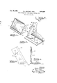
- FIG. 1 is a perspective view of a typical loader bucket with a cutting edge constructed in accordance with the present invention
- FIG. 2 is an enlarged fragmentary sectional view of one corner of the bucket illustrated in 'FIG. 1;
- FIG. 3 is a view in side elevation looking from the outer side of a corner bit which forms a part of the cutting edge of the present invention
- FIG. 4 is a front elevation of the same corner bit
- FIG. 5 is a cross sectional view taken on the line V--V of 'FIG. 2.
- the typical bucket illustrated in FIG. 1 has what will be termed for the purposes of the present description a bottom and sides 1-1 when it is in its digging or loading position, which is the position in which the cutting edges are employed.
- the forward edge of the bottom 10 as well as the forward edges of the sides .11, which are first to engage the earth in a digging operation, are reinforced by hardened steel plates welded in place, and when these plates are formed in the conventional manner of a single straight member for the bottom and two straight members for the sides, corner welds soften and tend to weaken them where they are joined and where they are subjected to the highest rate of wear. 7
- the present invention provides a straight hardened cutting edge 12 for the forward edge of the bottom of the red States Patent 0 3,014,293 Patented Dec. 26, 1961 "ice bucket and two corner bits generally indicated at 14 for the lower forward portions of the side edges of the bucket.
- the vertically extending portions of the corner bits may be of any desired length, and for practical purposes they are just sufiiciently long to insure that their upper ends are above the position where the edges are subjected to a high rate of wear.
- Hardened members 15 may be employed as continuation of the corner bits 14 and are the same in cross sectional configuration and joined to them as by Welding shown at 16 in FIG. 2 above the area of the greatest wear. :The corner bits as shown in FIGS.
- the bottom cutting edge 12 has its rear portion cut away adjacent the ends to receive the horizontal portion -17 of the corner bits as is best shown in FIG. 2, and the corner bits are welded to the bottom portion as shown at 19, the weld being spaced from the forward earth engaging edge of the member 12.
- a double V type weld may be provided for by forming the lower edges of the corner bits with chamfers as indicated at 20 in FIGS. 3 and 4, and similarly treating the edges of the recess in the member 1 2 to which the corner bits are welded.
- the entire assembly is welded to the forward edge of the bottom of the bucket, preferably on both sides as indicated at 22 and 23 in FIG.
- corner bits may be made by any conventional process, such as casting, forging or machining and may be hardened as a unit, while the long straight edge of the bottom member 12 is readily hardened by conventional heat treating methods and apparatus.
- a cutting edge for the bottom and contiguous sides of a loader bucket or the like which comprises a straight hardened member extending forwardly from the bottom and having recesses in its rear edge adjacent both ends, and two end bits each comprising a hardened angular member with one portion extending forwardly from a side of the bucket, and one portion lying within one of said recesses.
- a cutting edge for the bottom and contiguous sides of a loader bucket or the like which comprises a straight hardened member extending forwardly from the bottom and having recesses in its rear edge adjacent both ends, and two end bits each comprising a hardened'angular member with one portion extending forwardly from a side of the bucket, and one portion lying within one of said recesses and a line of welding joining said last portion to the straight hardened member within said recess with all of said welding disposed rearwardly of the forward cutting edge of said straight member.
- a cutting edge for the bottom and contiguous sides of a loader bucket or the like comprising a hardened member welded to and extending forwardly from each side and having a short angularly related portion in the plane of and extending forwardly from the bottom admember and to said angularly related portions of the side members.
Landscapes
- Engineering & Computer Science (AREA)
- Mechanical Engineering (AREA)
- Mining & Mineral Resources (AREA)
- Civil Engineering (AREA)
- General Engineering & Computer Science (AREA)
- Structural Engineering (AREA)
- Component Parts Of Construction Machinery (AREA)
- Shovels (AREA)
Description
1961 c. E. BOATMAN ETAL 3,014,293
CUTTING EDGE FOR LOADER BUCKETS OR THE LIKE Filed Jan. 13, 1961 INVENTORS Charles. E. Boafman BY Mar! 14/ Clark Eugene L.He/+on g ?-2 M TORNE'YS Z fornia Filed Jan. 13, 1961, Ser. No. 82,484 3 Claims. (Cl. 37-141) This invention relates to the cutting edges of buckets such as used on tractor mounted loaders or other earth moving machines and is directed particularly to the elimination of weak or soft portions in the cutting edge which result from welding or bending.
Cutting edges for earth moving tools are conventionally made of hardened steel. In buckets they comprise a straight section contiguous with the horizontal earth engaging edge of the bucket, and two sections contiguous with the edges of the side walls which meet the horizontal edge. Welding these sections together reduces their hardness because of the heat of welding creating soft areas subject to rapid wear and stress risers which lead to cracks or fractures in the surface. Bending the three sections from a single piece of stock also has disadvantages. Bending prior to hardening creates difliculties in the hardening process and bending after hardening requires heating which reduces hardness. Bending also reduces thickness at the corners of the bucket which are subject to the highest rate of wear and produces a rounded corner which is not adaptable to fastening means for teeth sometimes used on cutting edges.
It is the object of the present invention to provide an improved cutting edge for buckets or the like which is constructed of multiple hardened parts secured to each other and to the bucket by means so positioned as to avoid any weakening of the parts at points which are subjected to a high rate of wear in use.
Further and more specific objects and advantages of the invention and the manner in which it is carried into practice are made apparent in the following specification wherein reference is made to the accompanying drawmg.
In the drawing:
FIG. 1 is a perspective view of a typical loader bucket with a cutting edge constructed in accordance with the present invention;
FIG. 2 is an enlarged fragmentary sectional view of one corner of the bucket illustrated in 'FIG. 1;
FIG. 3 is a view in side elevation looking from the outer side of a corner bit which forms a part of the cutting edge of the present invention;
FIG. 4 is a front elevation of the same corner bit; and
FIG. 5 is a cross sectional view taken on the line V--V of 'FIG. 2.
The typical bucket illustrated in FIG. 1 has what will be termed for the purposes of the present description a bottom and sides 1-1 when it is in its digging or loading position, which is the position in which the cutting edges are employed. The forward edge of the bottom 10 as well as the forward edges of the sides .11, which are first to engage the earth in a digging operation, are reinforced by hardened steel plates welded in place, and when these plates are formed in the conventional manner of a single straight member for the bottom and two straight members for the sides, corner welds soften and tend to weaken them where they are joined and where they are subjected to the highest rate of wear. 7
The present invention provides a straight hardened cutting edge 12 for the forward edge of the bottom of the red States Patent 0 3,014,293 Patented Dec. 26, 1961 "ice bucket and two corner bits generally indicated at 14 for the lower forward portions of the side edges of the bucket. The vertically extending portions of the corner bits may be of any desired length, and for practical purposes they are just sufiiciently long to insure that their upper ends are above the position where the edges are subjected to a high rate of wear. Hardened members 15 may be employed as continuation of the corner bits 14 and are the same in cross sectional configuration and joined to them as by Welding shown at 16 in FIG. 2 above the area of the greatest wear. :The corner bits as shown in FIGS. 3 and 4, have a horizontal portion 17 and an upstanding portion 18 and the horizontal portion is of less width than the bottom cutting edge 12. The bottom cutting edge 12 has its rear portion cut away adjacent the ends to receive the horizontal portion -17 of the corner bits as is best shown in FIG. 2, and the corner bits are welded to the bottom portion as shown at 19, the weld being spaced from the forward earth engaging edge of the member 12. A double V type weld may be provided for by forming the lower edges of the corner bits with chamfers as indicated at 20 in FIGS. 3 and 4, and similarly treating the edges of the recess in the member 1 2 to which the corner bits are welded. The entire assembly is welded to the forward edge of the bottom of the bucket, preferably on both sides as indicated at 22 and 23 in FIG. 2, and the corner bits, as well as the upward extensions 18 thereof, are welded to the forward edges of the side walls 11 by a corner weld such as indicated at 24 in FIG. 5. The leading edges of all of the cutting members are beveled, as is conventional, to facilitate penetration of the earth, and as may be seen from the drawing, no welds or bends which create undesirable weak areas intercept any of these leading edges with the exception of the weld 16 which as previously stated is located in an area subject only to a low rate of wear.
One of the advantages of the invention resides in the fact that the corner bits may be made by any conventional process, such as casting, forging or machining and may be hardened as a unit, while the long straight edge of the bottom member 12 is readily hardened by conventional heat treating methods and apparatus.
While joining of the several parts has been described herein as by welding, the invention is applicable to cutting edge parts joined by other conventional methods such as riveting or bolting.
We claim:
1. A cutting edge for the bottom and contiguous sides of a loader bucket or the like which comprises a straight hardened member extending forwardly from the bottom and having recesses in its rear edge adjacent both ends, and two end bits each comprising a hardened angular member with one portion extending forwardly from a side of the bucket, and one portion lying within one of said recesses.
2. A cutting edge for the bottom and contiguous sides of a loader bucket or the like which comprises a straight hardened member extending forwardly from the bottom and having recesses in its rear edge adjacent both ends, and two end bits each comprising a hardened'angular member with one portion extending forwardly from a side of the bucket, and one portion lying within one of said recesses and a line of welding joining said last portion to the straight hardened member within said recess with all of said welding disposed rearwardly of the forward cutting edge of said straight member.
3. A cutting edge for the bottom and contiguous sides of a loader bucket or the like comprising a hardened member welded to and extending forwardly from each side and having a short angularly related portion in the plane of and extending forwardly from the bottom admember and to said angularly related portions of the side members.
References Cited in the file of this patent UNITED STATES PATENTS Page July 21, 1925 Robin et al. Sept. 8, 1931 M. Ma-M hi
Priority Applications (1)
| Application Number | Priority Date | Filing Date | Title |
|---|---|---|---|
| US82484A US3014293A (en) | 1961-01-13 | 1961-01-13 | Cutting edge for loader buckets or the like |
Applications Claiming Priority (1)
| Application Number | Priority Date | Filing Date | Title |
|---|---|---|---|
| US82484A US3014293A (en) | 1961-01-13 | 1961-01-13 | Cutting edge for loader buckets or the like |
Publications (1)
| Publication Number | Publication Date |
|---|---|
| US3014293A true US3014293A (en) | 1961-12-26 |
Family
ID=22171514
Family Applications (1)
| Application Number | Title | Priority Date | Filing Date |
|---|---|---|---|
| US82484A Expired - Lifetime US3014293A (en) | 1961-01-13 | 1961-01-13 | Cutting edge for loader buckets or the like |
Country Status (1)
| Country | Link |
|---|---|
| US (1) | US3014293A (en) |
Cited By (13)
| Publication number | Priority date | Publication date | Assignee | Title |
|---|---|---|---|---|
| US3243906A (en) * | 1963-10-14 | 1966-04-05 | Allis Chalmers Mfg Co | Excavating bucket structure |
| US3281972A (en) * | 1963-10-23 | 1966-11-01 | Sandor R Kerestes | Removable blade |
| US3736675A (en) * | 1971-01-13 | 1973-06-05 | Caterpillar Tractor Co | Corner construction for loader buckets or the like |
| US3941262A (en) * | 1974-02-01 | 1976-03-02 | Caterpillar Tractor Co. | Pivotally disposable bucket |
| US3984928A (en) * | 1975-07-11 | 1976-10-12 | Caterpillar Tractor Co. | Corner reinforcement for various sized loader buckets |
| US4127952A (en) * | 1977-06-20 | 1978-12-05 | Caterpillar Tractor Co. | Replaceable adapter for an earthworking tool |
| US4132181A (en) * | 1977-05-23 | 1979-01-02 | Ace Service Incorporated | Fertilizer applying knife assembly |
| US4360982A (en) * | 1981-03-02 | 1982-11-30 | J. I. Case Company | Bucket with removable cutting plate |
| USD344526S (en) | 1992-06-22 | 1994-02-22 | Vme Industries Sweden Ab | Excavating shovel |
| USD357260S (en) | 1992-06-22 | 1995-04-11 | Vme Industries Sweden Ab | Tilting bucket for material handling machines |
| USD554159S1 (en) * | 2006-08-16 | 2007-10-30 | Caterpillar Inc | Bucket base edge shroud system |
| US20220412042A1 (en) * | 2021-06-28 | 2022-12-29 | Caterpillar Inc. | Dipper lip |
| WO2023229832A1 (en) * | 2022-05-24 | 2023-11-30 | Caterpillar Inc. | Wing shroud |
Citations (2)
| Publication number | Priority date | Publication date | Assignee | Title |
|---|---|---|---|---|
| US1546791A (en) * | 1924-08-21 | 1925-07-21 | John W Page | Scraper bucket |
| US1822423A (en) * | 1929-12-28 | 1931-09-08 | G H Williams Company | Earth handling structure |
-
1961
- 1961-01-13 US US82484A patent/US3014293A/en not_active Expired - Lifetime
Patent Citations (2)
| Publication number | Priority date | Publication date | Assignee | Title |
|---|---|---|---|---|
| US1546791A (en) * | 1924-08-21 | 1925-07-21 | John W Page | Scraper bucket |
| US1822423A (en) * | 1929-12-28 | 1931-09-08 | G H Williams Company | Earth handling structure |
Cited By (15)
| Publication number | Priority date | Publication date | Assignee | Title |
|---|---|---|---|---|
| US3243906A (en) * | 1963-10-14 | 1966-04-05 | Allis Chalmers Mfg Co | Excavating bucket structure |
| US3281972A (en) * | 1963-10-23 | 1966-11-01 | Sandor R Kerestes | Removable blade |
| US3736675A (en) * | 1971-01-13 | 1973-06-05 | Caterpillar Tractor Co | Corner construction for loader buckets or the like |
| US3941262A (en) * | 1974-02-01 | 1976-03-02 | Caterpillar Tractor Co. | Pivotally disposable bucket |
| US3984928A (en) * | 1975-07-11 | 1976-10-12 | Caterpillar Tractor Co. | Corner reinforcement for various sized loader buckets |
| US4132181A (en) * | 1977-05-23 | 1979-01-02 | Ace Service Incorporated | Fertilizer applying knife assembly |
| US4127952A (en) * | 1977-06-20 | 1978-12-05 | Caterpillar Tractor Co. | Replaceable adapter for an earthworking tool |
| US4360982A (en) * | 1981-03-02 | 1982-11-30 | J. I. Case Company | Bucket with removable cutting plate |
| USD344526S (en) | 1992-06-22 | 1994-02-22 | Vme Industries Sweden Ab | Excavating shovel |
| USD357260S (en) | 1992-06-22 | 1995-04-11 | Vme Industries Sweden Ab | Tilting bucket for material handling machines |
| USD554159S1 (en) * | 2006-08-16 | 2007-10-30 | Caterpillar Inc | Bucket base edge shroud system |
| US20220412042A1 (en) * | 2021-06-28 | 2022-12-29 | Caterpillar Inc. | Dipper lip |
| US11926987B2 (en) * | 2021-06-28 | 2024-03-12 | Caterpillar Inc. | Dipper lip |
| WO2023229832A1 (en) * | 2022-05-24 | 2023-11-30 | Caterpillar Inc. | Wing shroud |
| US12460394B2 (en) | 2022-05-24 | 2025-11-04 | Caterpillar Inc. | Wing shroud |
Similar Documents
| Publication | Publication Date | Title |
|---|---|---|
| US3014293A (en) | Cutting edge for loader buckets or the like | |
| US3203488A (en) | Ripper tooth | |
| US3805423A (en) | Bi-metal ripper tip for digging teeth | |
| US3536147A (en) | Replaceable ripper tip assembly | |
| US4047312A (en) | Corner tooth assembly | |
| US3281972A (en) | Removable blade | |
| US4043060A (en) | Combination strengthened loader bucket and replaceable cutting edge | |
| US2148925A (en) | Method of repointing a worn excavator tooth | |
| US3049824A (en) | Digging tip | |
| US3063176A (en) | Replaceable ripper tip | |
| JPS6047128A (en) | Structure of abrasion part | |
| US1927818A (en) | Ripper tooth | |
| WO1997020111A1 (en) | High strength earth working tooth | |
| US2740212A (en) | Rooter tooth assembly | |
| US4204349A (en) | Corner tooth construction | |
| US2227674A (en) | Dipper tooth assembly | |
| US2397521A (en) | Rooter for excavators | |
| US3736675A (en) | Corner construction for loader buckets or the like | |
| US2369285A (en) | Dipper tooth | |
| US1716432A (en) | Excavating scoop | |
| US1522860A (en) | Teeth for excavating and dredging buckets | |
| US4098013A (en) | Digging tooth with replaceable cutting edge | |
| US2718162A (en) | Bucket tooth repointing | |
| US4027409A (en) | Ground engaging element having a controlled cutting edge | |
| US2990633A (en) | Dipper teeth |