US3003306A - Sprocket chain separator with means for measuring the desired length of chain - Google Patents
Sprocket chain separator with means for measuring the desired length of chain Download PDFInfo
- Publication number
- US3003306A US3003306A US70176157A US3003306A US 3003306 A US3003306 A US 3003306A US 70176157 A US70176157 A US 70176157A US 3003306 A US3003306 A US 3003306A
- Authority
- US
- United States
- Prior art keywords
- chain
- sprocket
- link
- detector
- switch
- Prior art date
- Legal status (The legal status is an assumption and is not a legal conclusion. Google has not performed a legal analysis and makes no representation as to the accuracy of the status listed.)
- Expired - Lifetime
Links
- 230000000994 depressogenic effect Effects 0.000 description 4
- 238000000926 separation method Methods 0.000 description 4
- 230000003111 delayed effect Effects 0.000 description 2
- 238000005259 measurement Methods 0.000 description 2
- 238000000034 method Methods 0.000 description 2
- 230000003405 preventing effect Effects 0.000 description 2
- 238000004064 recycling Methods 0.000 description 2
- 241000518994 Conta Species 0.000 description 1
- 101100066738 Neurospora crassa (strain ATCC 24698 / 74-OR23-1A / CBS 708.71 / DSM 1257 / FGSC 987) fkr-5 gene Proteins 0.000 description 1
- 229910000746 Structural steel Inorganic materials 0.000 description 1
- 208000027697 autoimmune lymphoproliferative syndrome due to CTLA4 haploinsuffiency Diseases 0.000 description 1
- 150000001768 cations Chemical class 0.000 description 1
- 238000010276 construction Methods 0.000 description 1
- 230000001276 controlling effect Effects 0.000 description 1
- 238000010586 diagram Methods 0.000 description 1
- 230000007257 malfunction Effects 0.000 description 1
- 238000004080 punching Methods 0.000 description 1
- 230000001105 regulatory effect Effects 0.000 description 1
- 239000002699 waste material Substances 0.000 description 1
Images


Classifications
-
- B—PERFORMING OPERATIONS; TRANSPORTING
- B25—HAND TOOLS; PORTABLE POWER-DRIVEN TOOLS; MANIPULATORS
- B25B—TOOLS OR BENCH DEVICES NOT OTHERWISE PROVIDED FOR, FOR FASTENING, CONNECTING, DISENGAGING OR HOLDING
- B25B27/00—Hand tools, specially adapted for fitting together or separating parts or objects whether or not involving some deformation, not otherwise provided for
- B25B27/14—Hand tools, specially adapted for fitting together or separating parts or objects whether or not involving some deformation, not otherwise provided for for assembling objects other than by press fit or detaching same
- B25B27/22—Hand tools, specially adapted for fitting together or separating parts or objects whether or not involving some deformation, not otherwise provided for for assembling objects other than by press fit or detaching same positioning sprocket chains, endless tracks, antiskid chains
-
- Y—GENERAL TAGGING OF NEW TECHNOLOGICAL DEVELOPMENTS; GENERAL TAGGING OF CROSS-SECTIONAL TECHNOLOGIES SPANNING OVER SEVERAL SECTIONS OF THE IPC; TECHNICAL SUBJECTS COVERED BY FORMER USPC CROSS-REFERENCE ART COLLECTIONS [XRACs] AND DIGESTS
- Y10—TECHNICAL SUBJECTS COVERED BY FORMER USPC
- Y10T—TECHNICAL SUBJECTS COVERED BY FORMER US CLASSIFICATION
- Y10T83/00—Cutting
- Y10T83/444—Tool engages work during dwell of intermittent workfeed
- Y10T83/4458—Work-sensing means to control work-moving or work-stopping means
- Y10T83/446—With means to initiate tool feed by same control impulse
Definitions
- invention relates to a method for separating lengths of roller chain from a stock roll of roller chain; and has for its primary object to automatically and mechanically measure a predetermined length of roller chain and to separate the length'fi-om the supply roll.
- Another object is to automatically remove both connecting pins of one link andito' discharge the extracted pins and chain links from the machine.
- Still another object is to eliminate the need for manual control," measurement or manipulation of the chain during the process of separation. 7
- Another object is to provide for the adjustment ot the 'machine to produce any one of a wide variety" of chain lengths.
- suitable-open areas may be located on the metering channel 34" as inithef case of the semi-circular slots 94, to: allowthe operator to remove the separated length of chain. Tr'ansverseiyeflhred to the drame' part 124? and adjacent to the metering channel 34 is movably mounted a conventional detecti'ngelectric switch mechanism which may'employ a switch of thejtype as Microswitch.”
- This switch 36a is. actuated by the leading or free end 38 ofthechain 20 as the chain slides down the metering channel 34.
- frame part 12a on which is se-' cured metering channel-134;is provided with a series of pairs of locating holes 35.
- a plate 37- is transversely secured by bolts 39" which may be passed” through any preselected pair of holes; depending onthe length of chaintobe separated.
- Pivoted' at 41 to plate a lever provided with a pin 45 arranged in path of chain 26; Asthechain slides down the metering channel 34, its leading end strikes pin 46, thereby swinging lever 43 in the direction shownby the arrow.
- FIGURE 1 shows a side view of a machine embodying
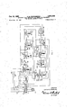
- FIG; 8 is a plan. view of the metering. device accord- I ing to the invention, and V 7
- FIG. 9 is -a schematic diagram showing. details of the withdrawal of pin and an operating circuit; for
- my chain separating machine 10 generally designated comprises a'channel iron and tubular constructed frame 12 which supports and contains an electrically operated, integrally" braked geared head motor 1 4* which drives through a slip clutch, sprocket 18' to deliver roller chain 20' from a reel 22 supportedon bracket through the machine 1.
- Fricalignment with the punch guide block guide holes 52 are" two punches 54 the axial spacing of which corresponds the circuit controlled by this switch.
- Pin 45 is slidably held in a hole extending across lever 43.
- a spring m betweenthelower surface/of lever 43 andan annular project-ion on pin '45 urges pin 45 downwards into metering channel 34 atall times.
- pin '45 does not obstruct metering chan-.
- nel 34* and;t he sprocket chain travelsf-reely into a suits ably placed receptacle.
- Afli'xed horizotally tothe top surface of cam 42 is another 58" which in its forward movement actuates lever 60 operating: air valve 62 to provide an blast through ports 64, 64 through suitable delivery lines 77,
- guid'e plate 30 and. block are secured to frame 12c by screws such 75.
- Pivumlly attached toi gnidcchannel26 in a horizontal is seming: 76 which when moved a recess in the guide plate is a chain positioner 40 which is moved verticallytdow'n actuates an electrical switch 78 to control the motor 14.
- the motor 14 is actuated by a manual start switch 132 and the roller chain 20 is delivered from the stock roll 22 over the driven sprocket 18 and through the guide channel 26 and down the metering channel 34.
- the switch 36 stops motor 14 and simultaneously energizes solenoid 50 actuating air valve 48.
- Air is supplied through line 88 to cylinder 46 producing forward motion of piston 90 and ram 44 with its attached cams 42 and 58 and punches 54.
- cam 42 moves forward it causes verticalmovement downward of the chain positioner 40 which engages the link to be disconnected and secures the link in axial alignment with punches 54.
- Further forward motion of ram 44 delivers the punches 54 to the heads of the link connecting pins 56 punching them out of the chain.
- cam 58 lifts lever 60 actuating air valve 62 providing an air blast through ports 64 to blow the extruded pins out of the openings '70.
- the extreme end 92 of cam 42 operates electrical switch 74 which reverses the action of cylinder 46 withdrawing the ram 44 and punches 54 allowing the unpinned connecting links to fall freely through opening 66.
- the separated length of chain may then be removed from the metering channel 34 by the operator at one or more of several semi-circular slots 94 located along metering channel 34.
- my apparatus can also readily be used to automatically and continuously cut and accumulate predetermined lengths of sprocket chain or to cut one length at a time, each time a cut length is removed. If the apparatus is to be used to accumulate a stock pile of cut chain then the switch 36 can be so located that once the separated length of chain is released, the chain slides down channel 34 into a storage bin thereby automatically allowing the cycle to repeat itself.
- Sprocket 18 may likewise be used as a metering device but in some cases may be less accurate than by locating switch 36 on channel 34.
- the electrical circuitry may be described as follows:
- Power supply lines 98, 100 and 102 provide electrical energy through suitable contacts 114 of relay 104.
- Switch 137 in conjunction with switch 36, through closed contact 116 forms the manual stopping circuit.
- Switch 137 is also a spring loaded switch that will cause contacts 138 to close upon releasing it.
- switch 137 is depressed opening contacts 138, since starting switch is not depressed and contacts 138 are open, no current can flow through 138 to send current to relay 104. Since no current flows through 116 relay 104 drops out of the circuit opening contacts 114 stopping the motor 14.
- relay 112 When starting switch 132 is depressed, as originally outlined, closing contacts 1234 relay 112 is energized by the closing of contact 136 that is current flowing from line 100, through contacts 136 past relay 112 to line 98 closing the circuit. Since relay 112 is energized contacts 130 are closed energizing relay 110 by sending current from line through contacts 130 past relay through contacts 118, since relay 104 is locked in, keeping contacts 118 closed, back to line 98 completing the circuit, thus closing contacts 128 and opening contact 126.
- Contact 128 holds relay 110 in by current flowing from line 100, through contact 128, past relay 110, through contact 118, and back to line 98 and holds relay 108 out of the circuit since relay 110 holds contacts 126 open preventing action of the ram 90 while the chain 20 is in motion. 7 t
- relay 104 drops out of the circuit due to the open contact 116, that is since current was flowing from line 100, past switch 74, through contacts 138, through contacts 122, past switch 36, through contacts 116, past relay 104 to line 98, keeping relay 104 in, and since there was no other way, by opening switch 36, the circuit is opened, no current flowing through the circuit.
- switch 36 opens the said circuit, it closes another circuit. That is this opens contacts 118 and contacts 114 thus stopping the motor 14.
- Switch 36 also energizes relay 108 by allowing current flowing from line 100, past switch 74 through contacts 138, through contacts 122 past switch 36 through closed contacts 126 to relay 108 back to line 98 closing the circuit. Since relay 108 is energized it will close contacts 124 thus energizing relay 106 by allowing the current to flow from line 100, through contacts 124 past relay 106, through contacts 118 and back to line 98 closing the circuit and closing contact 120. This action locks relay 108 in the circuit as long as the chain remains in contact with switch 36. This is so because current flows from line 100 past switch 74, through contacts 138 through contacts 122 past switch 36 through closed contacts 126, past relay 108' and back to line 98 completing the circuit.
- switch 78 When switch 78 is actuated by malfunctioning of the chain or by the termination of the supply of sprocket chain relay 146 is energized by current flowing from line 100, past switch 78, past relay 146 and back to line 98 a closing the circuit. This action opens contact 122 break ing the contact through contact 116 and switches 36 and l start, switch 132.
- Relay 152 is inserted between supply lines 98 and 100 and will close start switch 132 only if three contacts 148, 150 and 154 are simultaneously closed; Contacts 150and 154 are both normally closed Contact 150 opens upon operationof relay 104', he, assoon asrnotor :14 starts rotating and closes whenmotor 14 stops rotating in response to the operation of detector switch 36. As soon asv detector switch 36is.
- a chain separatingapparatus comprising a sourceof supply of sprocket chainrconsisting'of links formed by the leading end of said chain, a' link locatorfoontrolled by the actuation of said detector, and cross pin eje'ctors coacting with said locator andcontrolled bysaidi detector to displace pins from the'chain links to be separated each time said detector measures off the desired length of sprocket chain, ,and means for actuating" said link cator andsaid cross pin ejector-s.
- a chain separating apparatus comprising Ia source or supply, of sprocket chain, a chain feeding sprocket, a c drive for rotating'said sprocket to feed the leading end of said chain along a. predetermined and' attl'east partially downwardly inclined' meas'uring path, aslip clutch interposed between said drive andsaid sprocket to allow said sprocket to stand still whenever the resistance of said sprocket to turning by saiddrive exceeds a predetermined amount, a detector located near the end'of the inclined path” and, actuated by the leading end of said chain, a link locator controlled by the actuation of said detector, andchain pin ejectors coacting with said locator and controlled by said detector to displace'pins from the chain links to be separated each time said detector measuresolf the desired length of sprocket chain.
- a chain separating apparatus comprising a source of supply of sprocket chain consisting of links formed by side plates and cross pins, a chain feeding sprocket, a drive for rotating said sprocket to feed the leading end of said chain along a predetermined measuring passage which extends at least. partially downwardly for receiving the sprocket chain, a detector actuated by the leading end of said chain, a link locator controlled by the actuation of said detector, cross pin: ejectors coactin-g with said locator and controlledby said detector todisplace pins from the chain links to beseparated' each time said chain feeding 'sprockethas fed the desired length of sprocket chain, asecond detector, positioned above the.
- Apparatus tor separatingpredetermi'ned lengtlkof chain froma; reel ofispnocket chain comprising; means for feeding a predetermined length of chain fronr said reel, a link locatorsaid link locator" being ada'ptedtodi rectly engage and temporarily retain a predetermined positioned adjacent th m f u r a said sprocket, a link'locator said link locator being and said sprocket and" adapted to be actuatedeach time a said sprocket chain becomes deflected awayfrom its apair of pin ejecting plungers for ejecting.
- Apparatus for separating predetermined lengths of chain from a reel of sprocket chain comprising, a sprocket for'feedingchain' from a reel; drive means said sprocket, means controlling the amount ofch'ain fed by said sprocket, alink locator said'link locator being adapted to directly engage and temporarily a predetermined link, a link separator actnatedsaid oonflol each time said sprocket has fed a predetermined of chain from said reel, said separator having means, for actuating said link locator prior to the separation of said link,'and a blower for exerting a blastofairon the link to be separated during actuation of said link separir tor to elfect a removal of theseparated link away v the chain.
- Apparatus for separating predetermined lengths of chain from a reel ofsprocket chain comprisingas'procketf for feeding. chain from a" reel, for said sprocket means controllingthe amount or ted by adapted to directly engage and temporarily'retain a pro-i determinedlink, a link separator actuated laysaid eonml each time said sprocket has .feda predetermined amount of chain from said reel, said separatorhaving means for actuating said link locator prior to separation of said link, means foraanatingsaidlinklocator.
- a blower for exertinga blast of air on the link to be separated during actuation of said link separator to efiect aremoval of the separated link? by anobstruction, and anrincapacitating'device actuated by said detector forstopping the feed of sprocket chaih, each time said'detector is actuated by said chai an obstruction is encountered.
- a chain separating apparatus comprising a source of supply of sprocket chain, a chain feeding sprocket, a passage containing said sprocket chain, a detector measuring 01f a predetermined length of sprocket chain from the leading end, a link locator said link locator being adapted to directly engage and temporarily retain a link at the lagging end of the predetermined length of sprocket chain and a link separator actuated by said detector each time said sprocket has fed a predetermined amount of chain from said reel.
- a chain separating apparatus comprising a source of supplyof sprocket chain, a chain feeding sprocket, drive means for said sprocket, an at least partially downwardly inclined passage for receiving said sprocket chain, a detector measuring off a predetermined length of sprocket chain from the leading end, a link locator setting up and holding a link from said predetermined length of chain operated by said detector, a link separator operated by said detector said detector being located along said inclined passage and having means projecting thereinto for abutting said leading end and means for actuating said link locator and said link separator.
- a chain separating apparatus comprising a source of supply of sprocket chain, a chain feeding sprocket, means fordriving said sprocket, a detector for measuring a predetermined length of sprocket chain from the leading end of the chain fed by said sprocket, an at least partially downwardly inclined measuring passage adapted to slidingly support said chain and supporting said detector, a link locator setting up and holding a link from said predetermined length of chain operated by said detector, a sprocket pin ejector plunger coacting with said locator and operated by said detector to displace pins from the sprocket links, means for actuating said locator and said ejector plunger and an air jet positioned adjacent said pin ejector to direct a blast of air upon said pins and links to blow away the separated links and pins after they have been separated from the sprocket chain said air jet operated by said detector.
- a chain separating apparatus comprising a source of supply of sprocket chain, a chain feeding sprocket, a detector for measuring a predetermined length of chain fed by said sprocket, a link locator, a pin ejector member and an air jet in operating sequence with said locator, said pin ejector and air jet being regulated and actuated by a cam plungersaid cam plunger being energized by a pneumatic system controlled by said detector.
- a chainseparating apparatus comprising a source of supply of sprocket chain, a chain feeding sprocket, a measuringpassage which extends at least partially downwardlyfor receiving the sprocket chain, a detector for measuring a predetermined length of chain from the leading end of the sprocket chain fed by said sprocket said detector being located along said inclined passage and having means projecting thereinto for abutting said leading end, a safety device to stop said feeding sprocket each time an excessive quantity of chain is fed and a link separator actuated by said detector each time said sprocket has fed a predetermined amount of chain from said reel. 15.
- a chain separating apparatus comprising a source of supply of sprocket chain, a chain feeding sprocket, a detector for measuring variable predetermined length of sprocket chain fed by said feeding sprocket, a link locator and a chain pin ejector coacting with said locator to displace pins from the chain link to be separated said link locator being adapted to directly engage and temporarily retain a predetermined link.
- a chain separating apparatus comprising a source of supply of sprocket chain, a chain feeding sprocket, a measuring passage which extends at least partially downwardly for receiving the sprocket chain, a detector for measuring a predetermined length of sprocket chain fed by said feeding sprocket said detector being located along said inclined passage and having means projecting there into for abutting said leading end, a link locator, a chain pin ejector coacting with said locator to displace pins from the sprocket chain to be separated, another detector actuated by and coacting with said pin ejector to return said pin ejector releasing said predetermined length of chain.
- a chain separating apparatus comprising a source of supply of sprocket chain, a chain feeding sprocket, a detector for measuring a predetermined length of sprocket chain fed by said feeding sprocket, a link locator, a chain pin ejector coacting with said locator to displace pins from the sprocket chain to be separated, another detector actuated by and coacting with said pin ejector to return said pin ejector releasing said predetermined length of chain, and means reactivating the machine to measure another predetermined length of sprocket chain subsequently to the release of the preceding predetermined length of sprocket chain.
- a chain separating apparatus comprising a source of supply of sprocket chain, a feeding sprocket for feeding sprocket chain from said source of supply, a detector detecting a predetermined length of sprocket chain, an inclined passage containing said predetermined length of sprocket chain supporting said detector said detector being located along said inclined passage and having means proje'cting thereinto for abutting said leading end and a link separator actuated by said detector each time said sprocket has fed a predetermined amount of chain from said reel.
- a chain separating apparatus comprising a source of supply of sprocket chain, a chain feeding sprocket, a detector for measuring a predetermined length of sprocket chain from the leading end of the chain fed by said sprocket, an at least partially downwardly inclined measuring passage adapted to slidingly support said chain and supporting said detector, a separating station which includes a link locator setting up and holding a link from said predetermined length of chain operated by said detector, a chain pin ejector plunger coacting with said locator and operated by said detector to displace pins from the chain links, an air jet positioned adjacent said pin ejector to direct a blast of air upon said pins and links to blow away the separated links and pins after they have been separated from the sprocket chain said air jet operated by said detector, and a guide block for the chain, having a vertical chute which extends therethrough for allowing said separated links to fall downwardly therethrough.
- a chain separating apparatus comprising a chain feeding sprocket, a source of supply of sprocket chain, a drive for rotating said sprocket to feed the leading end of said sprocket chain along a predetermined at least partially downwardly inclined measuring passage, a slip clutch interposed between said drive and said sprocket, a detector located at the end of said passage and responsive to the leading end of said sprocket chain to detect predetermined lengths of sprocket chain, a link locator for positioning a link, a chain pin ejector coacting with said locator to eject chain pins, an air jet coacting with said pin ejector and said locator to blow away the separated links and pins after they have been separated from the sprocket chain, a second detector positioned above the predetermined passage of said sprocket chain in between said link locator and said sprocket and adapted to be actuated each time said sprocket chain becomes deflected away from
- a chain separating apparatus comprising a source of supply of sprocket chain consisting of links formed by side plates and cross pins, a chain feeding sprocket provided with toothed elements directly engaging with the cross pins, drive means for said procket, a measuring passage which extends at least partially downwardly for receiving the sprocket chain, a detector at the end of said passage for measuring a predetermined length of chain fed by said sprocket and actuated by an end link of the chain, a link locator, pin ejectors coacting with said locator to displace the cross pins from the links,
Landscapes
- Engineering & Computer Science (AREA)
- Mechanical Engineering (AREA)
- Devices For Conveying Motion By Means Of Endless Flexible Members (AREA)
Description
Oct. 10, 1961 c. E. QUISENBERRY 3,003,306
SPROCKET CHAIN SEPARATOR wma nuns FOR MEASURING THE DESIRED LENGTH OF CHAIN Filed D60. 10, 195'? 4 Sheets-Sheet 1 0 FIG 8 (3 45 MP a R47 1 39/@ 360 7 INVENTOR.
CARTER QUlSENBERRY j L grww AT TOR NEY 1961 c. E. QUISENBERRY 3,003,306
SPROCKET CHAIN SEPARATOR WITH MEANS FOR MEASURING THE DESIRED LENGTH OF CHAIN 4 Sheets-:Sheet 2 Filed Dec. 10, 195"! INV EN 1 OR.
CARTER QUI SEN BERRY mam ATTORNEV 4 Sheets-Sheet 4 J ATTORNEY 50 dO-PUU PU Oct. 10, 1961 c. E. QUISENBERRY SPROCKET CHAIN SEPARATOR WITH MEANS FOR msuamc Filed Dec. 10, 1957 THE DESIRED LENGTH OF CHAIN I. L E.
hm if. aokm.
. the. features of this invention.
' 3,003,306; a mom! CHAIN saranaron wrm MEANS non MEASURING run a summon Ca: N.Y., asslgnor to arican ac me oundry om any neon-porntinnotNewYork a Filed Dec. 10,, 1957, Ser. No. 701,761
21 Claims; '(Cl'.
invention relates to a method for separating lengths of roller chain from a stock roll of roller chain; and has for its primary object to automatically and mechanically measure a predetermined length of roller chain and to separate the length'fi-om the supply roll. i
Another object is to automatically remove both connecting pins of one link andito' discharge the extracted pins and chain links from the machine.
Still another object is to eliminate the need for manual control," measurement or manipulation of the chain during the process of separation. 7
Another object is to provide for the adjustment ot the 'machine to produce any one of a wide variety" of chain lengths.
These objects'and others may be attained by the em:-
- swam tlie' restlessnes- 16, I6 and 8 m in is adjustable by tightening or loosening nut 19; The mllerichain 20 passesover the sprocket lll and thence were guide channel 2 and over the guide block 3" ployment of this invention, which embodies such" feaa tures as. the automatic delivery of roller chain from a supplyroll and the metering thereof andthe automatic removalol' connecting pins and links, therebyseparating the metered length of chain from the supply. 7
Other features include the removal of the extracted pins and links from the'machine by an air blast and the automatic sensing andjoontrol of chain length, positiOn and provisions for stopping operation in: the event of malfunction of the roller chain.
Other objects andfeatures ofthe invention will appean asthe description of the particular physical. embodiment selected to illustrate the invention progresses. In the accompanying} drawings which form a part of this specifiand between guide plate and punch guide 32 and from thence out or chain separating mechanism and into the metering channel 34. 1! desired theqsides of the channel 34 bent inwardlyto so enclose roller chain that it could not double upon itself if the angle of channel 34-is too shallow." In
this case suitable-open areas may be located on the metering channel 34" as inithef case of the semi-circular slots 94, to: allowthe operator to remove the separated length of chain. Tr'ansverseiyeflhred to the drame' part 124? and adjacent to the metering channel 34 is movably mounted a conventional detecti'ngelectric switch mechanism which may'employ a switch of thejtype as Microswitch." This switch 36a is. actuated by the leading or free end 38 ofthechain 20 as the chain slides down the metering channel 34.
.Aeshown in FIG; 8, frame part 12a, on which is se-' cured metering channel-134;is provided with a series of pairs of locating holes 35. A plate 37-is transversely secured by bolts 39" which may be passed" through any preselected pair of holes; depending onthe length of chaintobe separated. Pivoted' at 41 to plate a lever provided with a pin 45 arranged in path of chain 26; Asthechain slides down the metering channel 34, its leading end strikes pin 46, thereby swinging lever 43 in the direction shownby the arrow.
' Lmnaae mses pin 47 of switch 36' therebyclosing cation like characters ofreference have been applied to correspondingpartsthroughout the several views-which. v
make. up the drawings.
FIGURE 1 shows a side view of a machine embodying,
FIG; 8 is a plan. view of the metering. device accord- I ing to the invention, and V 7 FIG. 9 is -a schematic diagram showing. details of the withdrawal of pin and an operating circuit; for
the start switch-132 shownin FIG. 7L 7 Referring to. the drawings in detail, my chain separating machine 10 generally designated comprises a'channel iron and tubular constructed frame 12 which supports and contains an electrically operated, integrally" braked geared head motor 1 4* which drives through a slip clutch, sprocket 18' to deliver roller chain 20' from a reel 22 supportedon bracket through the machine 1. The slipfl'clutch consists ofa pair offriction discs 16; 16, one on -each side of sprocket 1 8 A: nut I9 engages the threaded end portion of the hub onwhich frictiun" discs =16; 16 and sprocket 18 are mounted. Fricalignment with the punch guide block guide holes 52 are" two punches 54 the axial spacing of which corresponds the circuit controlled by this switch.
* Pin 45 is slidably held in a hole extending across lever 43. A spring m betweenthelower surface/of lever 43 andan annular project-ion on pin '45 urges pin 45 downwards into metering channel 34 atall times.
A delayed'r'eleaserelay 147 in the circuit of ram switch" 74; FIGJ'Z when energized, pulls" pin 45 upwards out of metering channel 34.- Thus as long as relay;147-
stays energized, pin '45 does not obstruct metering chan-.
nel 34* and;t=he sprocket chain travelsf-reely into a suits ably placed receptacle.
Located vertrcM y in stroke of a double-acting air cylinder 46 cont-rolled by a four-way air valve 48 actuated by a solenoid 50. This is astand'ard" unitas used on. spot welders. Rigidly attached to the ram 44 in a horizontal position andin axial-i to that of a pairofroller chain connecting pins 56. A single punch can be used in place of the twopunchesfl and inlthis' case only one connecting pin need be removed. I
Afli'xed horizotally tothe top surface of cam 42 is another 58" which in its forward movement actuates lever 60 operating: air valve 62 to provide an blast through ports 64, 64 through suitable delivery lines 77,
77" to blow" out the extruded pins and disconnected links from the roller chain; The waste links drop through a verticar opening in guide block 28' and are collected fall into my 65;
- As'shownin FKR 5, guide block, punch 32,,
Pivumlly attached toi gnidcchannel26 in a horizontal is seming: 76 which when moved a recess in the guide plate is a chain positioner 40 which is moved verticallytdow'n actuates an electrical switch 78 to control the motor 14. In the preferred embodiment of this invention, the motor 14 is actuated by a manual start switch 132 and the roller chain 20 is delivered from the stock roll 22 over the driven sprocket 18 and through the guide channel 26 and down the metering channel 34. When the end link 38 of the chain strikes the switch 36, it stops motor 14 and simultaneously energizes solenoid 50 actuating air valve 48. Air is supplied through line 88 to cylinder 46 producing forward motion of piston 90 and ram 44 with its attached cams 42 and 58 and punches 54. As cam 42 moves forward it causes verticalmovement downward of the chain positioner 40 which engages the link to be disconnected and secures the link in axial alignment with punches 54. Further forward motion of ram 44 delivers the punches 54 to the heads of the link connecting pins 56 punching them out of the chain.
Simultaneously the cam 58 lifts lever 60 actuating air valve 62 providing an air blast through ports 64 to blow the extruded pins out of the openings '70. At the end of the ramstroke, the extreme end 92 of cam 42 operates electrical switch 74 which reverses the action of cylinder 46 withdrawing the ram 44 and punches 54 allowing the unpinned connecting links to fall freely through opening 66. The separated length of chain may then be removed from the metering channel 34 by the operator at one or more of several semi-circular slots 94 located along metering channel 34.
It will be apparent that my apparatus can also readily be used to automatically and continuously cut and accumulate predetermined lengths of sprocket chain or to cut one length at a time, each time a cut length is removed. If the apparatus is to be used to accumulate a stock pile of cut chain then the switch 36 can be so located that once the separated length of chain is released, the chain slides down channel 34 into a storage bin thereby automatically allowing the cycle to repeat itself.
If the stock roll fails to unwind, excessive tension develops which causes clutch 16 to slip preventing chain breakage. When an obstruction prevents passage of the chain 20 through guide channel 26, the chain doubles upon itself causing sensing cam 76 to rise, thereby actuating electrical switch 78 stopping the motor 14. If the stock roll 22 is empty, no more roller chain 20 will pass through guide channel 26, the sensing cam 76 will then drop thereby again actuating electrical switch 78 in the opposite direction stopping the motor 14.
Various lengths of chain can be metered by locating.
In this arrangement the chain 20' is measured from the forward end giving a more accurate length measurement. Sprocket 18 may likewise be used as a metering device but in some cases may be less accurate than by locating switch 36 on channel 34.
Referring to FIG. 7, the electrical circuitry may be described as follows:
When the starting switch 132 is depressed manually, closing contacts 134 and 136 and opening contacts 133 and 135 the relay 104 is energized thus closing contacts 114, 116 and 1-18 opening contact 150 and starting the motor 14, the contacts 138 remaining closed. Since switch 132 is spring loaded upon releasing it, contacts 134 and 136 will open but motor 14 continues running even though the pressure on switch 132 is released, because relay 104 is locked in. This is accomplished since the current from line 100 flows past switch 74, past switch 137 through contacts 138, since it is still in closed position, through contacts 122, through switch 36, back to contacts 116 and back to line 98 completing the circuit.
4 l Switch 137 is also a spring loaded switch that will cause contacts 138 to close upon releasing it.
To manually stop motor 14 switch 137 is depressed opening contacts 138, since starting switch is not depressed and contacts 138 are open, no current can flow through 138 to send current to relay 104. Since no current flows through 116 relay 104 drops out of the circuit opening contacts 114 stopping the motor 14.
When starting switch 132 is depressed, as originally outlined, closing contacts 1234 relay 112 is energized by the closing of contact 136 that is current flowing from line 100, through contacts 136 past relay 112 to line 98 closing the circuit. Since relay 112 is energized contacts 130 are closed energizing relay 110 by sending current from line through contacts 130 past relay through contacts 118, since relay 104 is locked in, keeping contacts 118 closed, back to line 98 completing the circuit, thus closing contacts 128 and opening contact 126.
Contact 128 holds relay 110 in by current flowing from line 100, through contact 128, past relay 110, through contact 118, and back to line 98 and holds relay 108 out of the circuit since relay 110 holds contacts 126 open preventing action of the ram 90 while the chain 20 is in motion. 7 t
Releasing the manual switch 132 opening contacts 136 drops relay 112'out of the circuit restoring contact 126. At this point the motor 14 is operating and the chain 20 is advancing.
When the end of the chain 38 opens switch 36, relay 104 drops out of the circuit due to the open contact 116, that is since current was flowing from line 100, past switch 74, through contacts 138, through contacts 122, past switch 36, through contacts 116, past relay 104 to line 98, keeping relay 104 in, and since there was no other way, by opening switch 36, the circuit is opened, no current flowing through the circuit. When switch 36 opens the said circuit, it closes another circuit. That is this opens contacts 118 and contacts 114 thus stopping the motor 14.
When relay 106 is energized, contacts are closed energizing solenoid 50 actuating the ram 90 through the action of the valve 48. Ram 90 closes switch 74 at the end of its stroke thus energizing relay 112 since current flowing from line 100 past switch 74, past relay 112 and back to line 98 closing the circuit thus closes contact and energizes relay 110, opening contact 126 and closing contact 128. This action prevents flutter of valve 48 and also drops relay 108 out of the circuit through the open contact 126.
When relay 108 is out of the circuit, contact 124 opens, dropping relay 106, deenergizing solenoid 50 which reverses [the action of the valve 48 and cylinder 50 thus withdrawing ram 90 to its starting position and resetting switch 74.
The circuit is now restored for recycling.
When switch 78 is actuated by malfunctioning of the chain or by the termination of the supply of sprocket chain relay 146 is energized by current flowing from line 100, past switch 78, past relay 146 and back to line 98 a closing the circuit. This action opens contact 122 break ing the contact through contact 116 and switches 36 and l start, switch 132. Relay 152 is inserted between supply lines 98 and 100 and will close start switch 132 only if three contacts 148, 150 and 154 are simultaneously closed; Contacts 150and 154 are both normally closed Contact 150 opens upon operationof relay 104', he, assoon asrnotor :14 starts rotating and closes whenmotor 14 stops rotating in response to the operation of detector switch 36. As soon asv detector switch 36is. operated, it opens contact 154 which contact 154 now takes over the function of contact 150 to hold start switch 132 open until ram switch- 74 operates and relay 147' withdraws pin 45 from metering channel 34, thereby opening: contact l48'and closing contact 154 Contact I48 stays open until delayed action relay 147 is. released, i.e., until the severed length of sprocket chain has left meteringchannel 34. Closing of contact 148' automaticallyinitiates another cycle of the machine since" at. this time both conta'ctsw 150 and 154are closed.
The invention hereinabove described may therefore be varied in construction within the scope ofthe claims for the particular device selectedto' illustrate the invention but one of many possible embodiments of the same. The invention therefore is not to be restricted to the precise details of the structure shown and described.
What is claimedis: i n j 1; A chain separatingapparatus comprising a sourceof supply of sprocket chainrconsisting'of links formed by the leading end of said chain, a' link locatorfoontrolled by the actuation of said detector, and cross pin eje'ctors coacting with said locator andcontrolled bysaidi detector to displace pins from the'chain links to be separated each time said detector measures off the desired length of sprocket chain, ,and means for actuating" said link cator andsaid cross pin ejector-s.
2." A chain separating apparatus comprising Ia source or supply, of sprocket chain, a chain feeding sprocket, a c drive for rotating'said sprocket to feed the leading end of said chain along a. predetermined and' attl'east partially downwardly inclined' meas'uring path, aslip clutch interposed between said drive andsaid sprocket to allow said sprocket to stand still whenever the resistance of said sprocket to turning by saiddrive exceeds a predetermined amount, a detector located near the end'of the inclined path" and, actuated by the leading end of said chain,a link locator controlled by the actuation of said detector, andchain pin ejectors coacting with said locator and controlled by said detector to displace'pins from the chain links to be separated each time said detector measuresolf the desired length of sprocket chain.
3; A chain separating apparatus comprising a source of supply of sprocket chain consisting of links formed by side plates and cross pins, a chain feeding sprocket, a drive for rotating said sprocket to feed the leading end of said chain along a predetermined measuring passage which extends at least. partially downwardly for receiving the sprocket chain, a detector actuated by the leading end of said chain, a link locator controlled by the actuation of said detector, cross pin: ejectors coactin-g with said locator and controlledby said detector todisplace pins from the chain links to beseparated' each time said chain feeding 'sprockethas fed the desired length of sprocket chain, asecond detector, positioned above the. predeterminedpath of said'chain in betweensaid lo'cator station normal..ottraveljby an obstruction, and means emnecting said second detector with said drive to tate the samewhen'ever said seconddeteetor is {4L App'a'rams for separating predetermined 138 of chain from a reel of sprocket chain committing, mean for feeding a predetermined length ofchainflfronr said met, a link locator positioned adjacent of travel of said chain,,said link locator being adapted to directly I engage and temporarily retain a predetermined: link, a pair of pin ejecting plungers forejecting the" a link that has been engaged by said locator, and for causing a new length hasbeen separated. V p t 5. Apparatus tor separatingpredetermi'ned lengtlkof chain froma; reel ofispnocket chain comprising; means for feeding a predetermined length of chain fronr said reel, a link locatorsaid link locator" being ada'ptedtodi rectly engage and temporarily retain a predetermined positioned adjacent th m f u r a said sprocket, a link'locator said link locator being and said sprocket and" adapted to be actuatedeach time a said sprocket chain becomes deflected awayfrom its apair of pin ejecting plungers for ejecting. the fiom a link that has been locatedtb'y' said" locator, an ah it! positioned adjacent. said pin ejecting plungers to direct a blast of air upon said pins and locatedlinks when said pin ejector is actuated to blow away'the andrthe pins after they have been separatedfiomflie a link separator actuated by said measuring" means each s time said "sprocket has fed a predetermined amount or chain from said reel, said link separator having. means for actuating said link locator prior to the separation of said link.
7. Apparatus for separating predetermined lengths of chain from a reel of sprocket chain comprising, a sprocket for'feedingchain' from a reel; drive means said sprocket, means controlling the amount ofch'ain fed by said sprocket, alink locator said'link locator being adapted to directly engage and temporarily a predetermined link, a link separator actnatedsaid oonflol each time said sprocket has fed a predetermined of chain from said reel, said separator having means, for actuating said link locator prior to the separation of said link,'and a blower for exerting a blastofairon the link to be separated during actuation of said link separir tor to elfect a removal of theseparated link away v the chain.
8.. Apparatus for separating predetermined lengths of chain from a reel ofsprocket chain comprisingas'procketf for feeding. chain from a" reel, for said sprocket means controllingthe amount or ted by adapted to directly engage and temporarily'retain a pro-i determinedlink, a link separator actuated laysaid eonml each time said sprocket has .feda predetermined amount of chain from said reel, said separatorhaving means for actuating said link locator prior to separation of said link, means foraanatingsaidlinklocator. and saidseparator, a blower for exertinga blast of air on the link to be separated during actuation of said link separator to efiect aremoval of the separated link? by anobstruction, and anrincapacitating'device actuated by said detector forstopping the feed of sprocket chaih, each time said'detector is actuated by said chai an obstruction is encountered. a
' 9; A- chain separating apparatusco i of supply of sprocket a chain feeding'sprockeflt of chain to be a; link 7 detector for measuring a predetermined length of sprocket chain from the leading end of the chain fed by said sprocket, an inclined passage for receiving said sprocket chain, said detector being located along said inclined passage and having means projecting thereinto for abutting said leading end and a link separator actuated by said detector each time said'sprocket has fed a predetermined amount of chain from said reel.
10.- A chain separating apparatus comprising a source of supply of sprocket chain, a chain feeding sprocket, a passage containing said sprocket chain, a detector measuring 01f a predetermined length of sprocket chain from the leading end, a link locator said link locator being adapted to directly engage and temporarily retain a link at the lagging end of the predetermined length of sprocket chain and a link separator actuated by said detector each time said sprocket has fed a predetermined amount of chain from said reel.
11. A chain separating apparatus comprising a source of supplyof sprocket chain, a chain feeding sprocket, drive means for said sprocket, an at least partially downwardly inclined passage for receiving said sprocket chain, a detector measuring off a predetermined length of sprocket chain from the leading end, a link locator setting up and holding a link from said predetermined length of chain operated by said detector, a link separator operated by said detector said detector being located along said inclined passage and having means projecting thereinto for abutting said leading end and means for actuating said link locator and said link separator.
12. A chain separating apparatus comprising a source of supply of sprocket chain, a chain feeding sprocket, means fordriving said sprocket, a detector for measuring a predetermined length of sprocket chain from the leading end of the chain fed by said sprocket, an at least partially downwardly inclined measuring passage adapted to slidingly support said chain and supporting said detector, a link locator setting up and holding a link from said predetermined length of chain operated by said detector, a sprocket pin ejector plunger coacting with said locator and operated by said detector to displace pins from the sprocket links, means for actuating said locator and said ejector plunger and an air jet positioned adjacent said pin ejector to direct a blast of air upon said pins and links to blow away the separated links and pins after they have been separated from the sprocket chain said air jet operated by said detector. 7
13. A chain separating apparatus comprising a source of supply of sprocket chain, a chain feeding sprocket, a detector for measuring a predetermined length of chain fed by said sprocket, a link locator, a pin ejector member and an air jet in operating sequence with said locator, said pin ejector and air jet being regulated and actuated by a cam plungersaid cam plunger being energized by a pneumatic system controlled by said detector.
14. A chainseparating apparatus comprising a source of supply of sprocket chain, a chain feeding sprocket, a measuringpassage which extends at least partially downwardlyfor receiving the sprocket chain, a detector for measuring a predetermined length of chain from the leading end of the sprocket chain fed by said sprocket said detector being located along said inclined passage and having means projecting thereinto for abutting said leading end, a safety device to stop said feeding sprocket each time an excessive quantity of chain is fed and a link separator actuated by said detector each time said sprocket has fed a predetermined amount of chain from said reel. 15. A chain separating apparatus comprising a source of supply of sprocket chain, a chain feeding sprocket, a detector for measuring variable predetermined length of sprocket chain fed by said feeding sprocket, a link locator and a chain pin ejector coacting with said locator to displace pins from the chain link to be separated said link locator being adapted to directly engage and temporarily retain a predetermined link.
16. A chain separating apparatus comprising a source of supply of sprocket chain, a chain feeding sprocket, a measuring passage which extends at least partially downwardly for receiving the sprocket chain, a detector for measuring a predetermined length of sprocket chain fed by said feeding sprocket said detector being located along said inclined passage and having means projecting there into for abutting said leading end, a link locator, a chain pin ejector coacting with said locator to displace pins from the sprocket chain to be separated, another detector actuated by and coacting with said pin ejector to return said pin ejector releasing said predetermined length of chain. I
17. A chain separating apparatus comprising a source of supply of sprocket chain, a chain feeding sprocket, a detector for measuring a predetermined length of sprocket chain fed by said feeding sprocket, a link locator, a chain pin ejector coacting with said locator to displace pins from the sprocket chain to be separated, another detector actuated by and coacting with said pin ejector to return said pin ejector releasing said predetermined length of chain, and means reactivating the machine to measure another predetermined length of sprocket chain subsequently to the release of the preceding predetermined length of sprocket chain.
18. A chain separating apparatus comprising a source of supply of sprocket chain, a feeding sprocket for feeding sprocket chain from said source of supply, a detector detecting a predetermined length of sprocket chain, an inclined passage containing said predetermined length of sprocket chain supporting said detector said detector being located along said inclined passage and having means proje'cting thereinto for abutting said leading end and a link separator actuated by said detector each time said sprocket has fed a predetermined amount of chain from said reel.
19. A chain separating apparatus comprising a source of supply of sprocket chain, a chain feeding sprocket, a detector for measuring a predetermined length of sprocket chain from the leading end of the chain fed by said sprocket, an at least partially downwardly inclined measuring passage adapted to slidingly support said chain and supporting said detector, a separating station which includes a link locator setting up and holding a link from said predetermined length of chain operated by said detector, a chain pin ejector plunger coacting with said locator and operated by said detector to displace pins from the chain links, an air jet positioned adjacent said pin ejector to direct a blast of air upon said pins and links to blow away the separated links and pins after they have been separated from the sprocket chain said air jet operated by said detector, and a guide block for the chain, having a vertical chute which extends therethrough for allowing said separated links to fall downwardly therethrough.
20. A chain separating apparatus comprising a chain feeding sprocket, a source of supply of sprocket chain, a drive for rotating said sprocket to feed the leading end of said sprocket chain along a predetermined at least partially downwardly inclined measuring passage, a slip clutch interposed between said drive and said sprocket, a detector located at the end of said passage and responsive to the leading end of said sprocket chain to detect predetermined lengths of sprocket chain, a link locator for positioning a link, a chain pin ejector coacting with said locator to eject chain pins, an air jet coacting with said pin ejector and said locator to blow away the separated links and pins after they have been separated from the sprocket chain, a second detector positioned above the predetermined passage of said sprocket chain in between said link locator and said sprocket and adapted to be actuated each time said sprocket chain becomes deflected away from its normal path of travel by an obstruction, said second detector detecting the end of the source of supply of sprocket chain, and a release to permit free travel of the said predetermined length of sprocket chain after the link separator separates said chain recycling the chain separating apparatus.
' 21. A chain separating apparatus comprising a source of supply of sprocket chain consisting of links formed by side plates and cross pins, a chain feeding sprocket provided with toothed elements directly engaging with the cross pins, drive means for said procket, a measuring passage which extends at least partially downwardly for receiving the sprocket chain, a detector at the end of said passage for measuring a predetermined length of chain fed by said sprocket and actuated by an end link of the chain, a link locator, pin ejectors coacting with said locator to displace the cross pins from the links,
and means controlled by said detector for actuating said link locator and said pin eiectors each time said detector has measured a predetermined length of chain.
" References cm in the file of this patent UNITED STATES PATENTS 1,174,349 Reynolds Mar. 7, 1916 1,206,086 Benjamin et a1. Nov. 28, 1916 2,247,766 Boerger July' 1, 1941 2,433,444 Eichinger Dec. 30,1947 2,700,870 Green Feb.- 1, 1955 Elliott et al. May 1, 1956
Priority Applications (1)
| Application Number | Priority Date | Filing Date | Title |
|---|---|---|---|
| US70176157 US3003306A (en) | 1957-12-10 | 1957-12-10 | Sprocket chain separator with means for measuring the desired length of chain |
Applications Claiming Priority (1)
| Application Number | Priority Date | Filing Date | Title |
|---|---|---|---|
| US70176157 US3003306A (en) | 1957-12-10 | 1957-12-10 | Sprocket chain separator with means for measuring the desired length of chain |
Publications (1)
| Publication Number | Publication Date |
|---|---|
| US3003306A true US3003306A (en) | 1961-10-10 |
Family
ID=24818567
Family Applications (1)
| Application Number | Title | Priority Date | Filing Date |
|---|---|---|---|
| US70176157 Expired - Lifetime US3003306A (en) | 1957-12-10 | 1957-12-10 | Sprocket chain separator with means for measuring the desired length of chain |
Country Status (1)
| Country | Link |
|---|---|
| US (1) | US3003306A (en) |
Cited By (8)
| Publication number | Priority date | Publication date | Assignee | Title |
|---|---|---|---|---|
| US3058295A (en) * | 1960-11-30 | 1962-10-16 | Mine Safety Appliances Co | Explosive tool for removing sprocket chain pivot pins |
| US3130476A (en) * | 1958-06-18 | 1964-04-28 | Gen Zipper Corp | Scoop cutting and bottom stop machines combination the machines and control means therefor |
| US3160095A (en) * | 1963-08-30 | 1964-12-08 | Dale Marking Equipment Co Inc | Web printing and cutting apparatus delivering a succession of identical sheets |
| US3182441A (en) * | 1961-03-30 | 1965-05-11 | Grinnell Corp | Chain riveting machine |
| US3377797A (en) * | 1964-10-29 | 1968-04-16 | Julius A. Pinchev | Automatic disassembling machine for riveted roller chain pin links |
| US3425213A (en) * | 1964-04-20 | 1969-02-04 | Albert Monash | Chain cutter and assembly apparatus |
| US3760586A (en) * | 1970-07-03 | 1973-09-25 | Tsubakimoto Chain Co | Automatic chain cutting machine |
| WO2023097352A1 (en) * | 2021-12-03 | 2023-06-08 | Eudey Stephen | Processing chains |
Citations (6)
| Publication number | Priority date | Publication date | Assignee | Title |
|---|---|---|---|---|
| US1174349A (en) * | 1912-11-27 | 1916-03-07 | Mergenthaler Linotype Gmbh | Machine-tool. |
| US1206086A (en) * | 1914-03-02 | 1916-11-28 | Benjamin Electric Mfg Co | Apparatus for delivering an intermittent air-blast. |
| US2247766A (en) * | 1939-06-03 | 1941-07-01 | Modine Mfg Co | Cutoff machine |
| US2433444A (en) * | 1944-05-02 | 1947-12-30 | Gen Cable Corp | Fault detector |
| US2700870A (en) * | 1949-05-16 | 1955-02-01 | Mitchell Smith | Machine to assemble chain structures with pin remover for producing chains of definite lengths |
| US2743925A (en) * | 1952-07-25 | 1956-05-01 | United Shoe Machinery Corp | Machines for performing operations with respect to articles and control mechanisms therefor |
-
1957
- 1957-12-10 US US70176157 patent/US3003306A/en not_active Expired - Lifetime
Patent Citations (6)
| Publication number | Priority date | Publication date | Assignee | Title |
|---|---|---|---|---|
| US1174349A (en) * | 1912-11-27 | 1916-03-07 | Mergenthaler Linotype Gmbh | Machine-tool. |
| US1206086A (en) * | 1914-03-02 | 1916-11-28 | Benjamin Electric Mfg Co | Apparatus for delivering an intermittent air-blast. |
| US2247766A (en) * | 1939-06-03 | 1941-07-01 | Modine Mfg Co | Cutoff machine |
| US2433444A (en) * | 1944-05-02 | 1947-12-30 | Gen Cable Corp | Fault detector |
| US2700870A (en) * | 1949-05-16 | 1955-02-01 | Mitchell Smith | Machine to assemble chain structures with pin remover for producing chains of definite lengths |
| US2743925A (en) * | 1952-07-25 | 1956-05-01 | United Shoe Machinery Corp | Machines for performing operations with respect to articles and control mechanisms therefor |
Cited By (9)
| Publication number | Priority date | Publication date | Assignee | Title |
|---|---|---|---|---|
| US3130476A (en) * | 1958-06-18 | 1964-04-28 | Gen Zipper Corp | Scoop cutting and bottom stop machines combination the machines and control means therefor |
| US3058295A (en) * | 1960-11-30 | 1962-10-16 | Mine Safety Appliances Co | Explosive tool for removing sprocket chain pivot pins |
| US3182441A (en) * | 1961-03-30 | 1965-05-11 | Grinnell Corp | Chain riveting machine |
| US3160095A (en) * | 1963-08-30 | 1964-12-08 | Dale Marking Equipment Co Inc | Web printing and cutting apparatus delivering a succession of identical sheets |
| US3425213A (en) * | 1964-04-20 | 1969-02-04 | Albert Monash | Chain cutter and assembly apparatus |
| US3377797A (en) * | 1964-10-29 | 1968-04-16 | Julius A. Pinchev | Automatic disassembling machine for riveted roller chain pin links |
| US3760586A (en) * | 1970-07-03 | 1973-09-25 | Tsubakimoto Chain Co | Automatic chain cutting machine |
| WO2023097352A1 (en) * | 2021-12-03 | 2023-06-08 | Eudey Stephen | Processing chains |
| US20250018462A1 (en) * | 2021-12-03 | 2025-01-16 | Stephen Eudey | Processing chains |
Similar Documents
| Publication | Publication Date | Title |
|---|---|---|
| US3177749A (en) | Control for feeding, measuring, and cutting strip material | |
| US2754860A (en) | Fastener feeding and driving mechanism | |
| US2408363A (en) | Electrically controlled strip serving machine | |
| US3003306A (en) | Sprocket chain separator with means for measuring the desired length of chain | |
| US2674311A (en) | Machine for cutting slugs and positioning them on transfer sheets | |
| US2943335A (en) | Electrically operated pneumatic apparatus for automatically assembling nuts and bolts | |
| US4341522A (en) | Method and apparatus for making pouches with dispensing fittings | |
| US4459884A (en) | Method of and apparatus for processing a pair of slide fastener stringers | |
| US2749981A (en) | Machine for automatically cutting off strips of uniformly increasing lengths from strip stock of indefinite length | |
| US2216629A (en) | Slitting and cutoff mechanism for sheet material | |
| US3939542A (en) | Method for inserting connecting pins in a printed circuit and machine for executing said method | |
| US4043232A (en) | Automatic cutting machine for continuous tapes | |
| US2355556A (en) | Cushion blanking die | |
| US2772705A (en) | Mold filling machine | |
| US2798548A (en) | Cutting machine for cutting extruded plastics | |
| US3256557A (en) | Machine for forming shaped articles of meat and the like and for supplying paper sheets and the like | |
| US2916811A (en) | Machine for assembling a tube into a plug | |
| US2652167A (en) | Automatic riveting machine | |
| JPH0274207A (en) | Apparatus for inserting a runner in a long continuous band piece of slide fastener | |
| US2900662A (en) | Molding machine | |
| US3418096A (en) | Operational safety mold cam bypass | |
| US2580883A (en) | Apparatus for heating and pressing thermoplastic sheet material | |
| US2244425A (en) | Die casting machine | |
| US3184229A (en) | Intermittent motion drive mechanism | |
| US4568406A (en) | Cap-lining machine |