US3001069A - Straight-line-frequency tuner - Google Patents
Straight-line-frequency tuner Download PDFInfo
- Publication number
- US3001069A US3001069A US598272A US59827256A US3001069A US 3001069 A US3001069 A US 3001069A US 598272 A US598272 A US 598272A US 59827256 A US59827256 A US 59827256A US 3001069 A US3001069 A US 3001069A
- Authority
- US
- United States
- Prior art keywords
- line
- tuner
- inductance
- point
- frequency
- Prior art date
- Legal status (The legal status is an assumption and is not a legal conclusion. Google has not performed a legal analysis and makes no representation as to the accuracy of the status listed.)
- Expired - Lifetime
Links
- 239000003990 capacitor Substances 0.000 description 14
- 230000000694 effects Effects 0.000 description 5
- 239000004020 conductor Substances 0.000 description 3
- 230000007423 decrease Effects 0.000 description 3
- CWYNVVGOOAEACU-UHFFFAOYSA-N Fe2+ Chemical compound [Fe+2] CWYNVVGOOAEACU-UHFFFAOYSA-N 0.000 description 2
- 238000010276 construction Methods 0.000 description 2
- 230000001965 increasing effect Effects 0.000 description 2
- 230000001939 inductive effect Effects 0.000 description 2
- 230000000903 blocking effect Effects 0.000 description 1
- 230000003247 decreasing effect Effects 0.000 description 1
- 238000010586 diagram Methods 0.000 description 1
- 230000014509 gene expression Effects 0.000 description 1
- 238000004519 manufacturing process Methods 0.000 description 1
- 239000000463 material Substances 0.000 description 1
- 238000000034 method Methods 0.000 description 1
- 238000012986 modification Methods 0.000 description 1
- 230000004048 modification Effects 0.000 description 1
- 238000005476 soldering Methods 0.000 description 1
Images
Classifications
-
- H—ELECTRICITY
- H03—ELECTRONIC CIRCUITRY
- H03H—IMPEDANCE NETWORKS, e.g. RESONANT CIRCUITS; RESONATORS
- H03H5/00—One-port networks comprising only passive electrical elements as network components
- H03H5/003—One-port networks comprising only passive electrical elements as network components comprising distributed impedance elements together with lumped impedance elements
Definitions
- This invention relates generally to tuners which are adaptable for ultra-high-frequency operation, and relates particularly to such tuners that are capable of providing straight-line-frequency operation.
- a tuner is basically a resonant device which can have its resonant frequency varied in a controlled manner over a given range.
- a straight-line-frequency tuner is a tuner which has a substantially linear relationship between its resonant frequency and the variation of its control means, which often is a rotatable shaft.
- control means is a rotatable shaft, and a straight-line-frequency characteristic is provided between rotation of its shaft and its resonant frequency.
- the invention provides a tuner having simple and economical construction, while providing straight-line-frequency operation.
- the principal object of this invention to provide an ultra-high-frequency tuner that has straightline-frequency operation and that is simple in construction, space-saving, and economical to make in production.
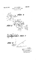
- FIGURE 1 illustrates the basic layout of the invention
- FIGURE 3 is a sectional view taken along line 3--3 in FIGURE 2; and, 1
- FIGURE 4 is a diagram illustrating the operational capabilities of the invention.
- FIG- URE 1 illustrates the basic form of the invention, which has a variable-inductance element of conducting material having a circular shape.
- a rotatable inductance arm 11 is grounded at a pivoting point 12.
- a capacitor 16 is fixed between ground and one end of circular-inductance member 10. Its value includes a combination of distributed, stray, tube and any trimmer capacitance which may be associated with it.
- Circular-inductance member 10 is formed as follows: A line is drawn through a pair of points P and Q. These points will lay on circular member 10, when it is constructed. A distance D exists between points P and Q.
- Point 12 is laid out on line PQ, and it will have a distance I from point Q and a distance B from point P.
- the distances D, I and B have substantially the following ratios:
- a line 17 is constructed through point 12 at an angle of 60 degrees with respect to line B.
- a second point 18 is provided on line 17 at a distance M from pivoting point 12.
- Distance M is related to distance D by the following ratio:
- Point 18 provides the center of a circle that defines circular-inductance element 10.
- Inductance element 10 preferably extends at least about the smaller portion of the circle intersected by line PQ, which is a chord of the circle. Thus, degrees of rotation are provided in rotating inductance arm 11 from point Q to point P.
- the straight-line-frequency characteristic of this invention is primarily obtained in rotating arm 11 between points Q and P. Accordingly, circular element 10 need not be extended much beyond point P. However, an initial inductance for the tuned circuit may be provided by extending circular-element 10 beyond point Q.
- a resonant circuit can be traced from ground through capacitor 16, through the fixed-inductance portion of circular member 10 up to point Q, through the adjustable length of circular member 10 between points Q and 13, and through the active-arm length between point 13 and grounded point 12.
- the range and absolute frequency values of the form of the invention in FIGURE 1 are primarily controlled by the diameter of wire 10 and its length.
- Capacitor 16 may be made adjustable to provide an adjustment at the high-frequency end of the tunable range of the tuner. Its adjustment will not substantially affect the straight-line-frequency characteristic of the invention or its frequency range.
- FIGURE 2 The form of the invention in FIGURE 2 is similar to the form shown in FIGURE 1, and its circular element is constructed by the same method.
- annular plate 20 of non-ferrous conducting material forms the circular-inductance element in FIGURE 2 and is comparable to circular member 10 in FIGURE 1.
- the center-line 25 of the plate may be constructed in the same manner as the circle of FIGURE 1.
- annular member in FIG URE 2 a pair of points P and Q are provided and a line is drawn between them to define the chord of a circle.
- the spacing between points P and Q determines to a first order of magnitude the size of the tuner and its frequency of operation.
- Pivoting point 22 is determined along chord PQ by the ratios of Formulas 1, 2, and 3 above. A sixty-degree line 27 is drawn, and center point 22 is provided using the ratio of Formula 4 above.-
- Center line of annular member 20 can then be drawn, since its radius will extend from point 22 to either point P or Q.
- a lip member 29 provides an adjustable inductance at the high-frequency end of tuner operation. This added inductance makes a smaller frequency range with better stability. It is connected to plate 20 at its end 30 and has its main portion separated therefrom by a slotted space 4.1. A shorting member 42 is located in slot 41 and is adjustable along the slot. Positioning of member 42 along slot 41 provides an inductance adjustment for the tuner. Once the adjustment is made, member 42 may be permanently fixed, such as by soldering.
- a capacitor 26 is connected between ground and the end portion 30. If there is a proper amount of stray or tube capacitance, capacitor 26 may be eliminated and a trimmer adjustment may be obtained by adjusting the inductance of portion 30-Q by positioning member 42. On the other hand, if capacitor 26 is adjustable then a two point adjustment is provided for aligning the frequency and range of the tuner.
- a blocking capacitor is provided by a circular plate 31, with respect to the ground plane.
- plate 31 is separated from a ground-plane plate 32 by a dielectric 33.
- Dielectric 33 also insulatingly separates annular inductance member 20 and lip member 29 from ground-plane 32. Dielectric 33- should he thin to obtain a large capacitance for plate 31.
- plate 31, dielectric 33, and ground plate 32 (shown in FIGURE 3) provide a large capacitance at ultra-high-frequencies to, in effect, maintain plate 31 at substantially ground potential for radio frequencies.
- plate 31 is insulated from ground and it permits direct-current potentials on the tuner, which are essential when the tuner is utilized in the plate circuit of a vacuum tube.
- Tuning arm 21 in FIGURE 2 is formed of non-ferrous material of high conductivity and has a V-shaped portion 24 that provides substantially line contact with the surface of circular-inductance plate 20.
- a plurality of V-shaped portions 24 may be used where the power capacity of the tuner is large to improve efliciency. Its straight-line-frequency characteristic is indicated by line 41 in FIGURE 4.
- the tuning range of the invention can be extended without greatly deviating from the straight-line-frequency characteristic of the tuner by connecting a linearly-variable capacitor in parallel with either capacitor 16 or 26. That is, the capacitance of the added capacitor varies linearly with shaft rotation, with adjustable tabs being preferably provided.
- a straight-line-frequency tuner comprising an inductance member formed as a circular arc, withsaid circle having a chord, a pivoting point dividing said chord into two parts having a ratio of about 0.717, and the center of said circular are being located on a line positioncd about 60 degrees from the larger of said two chord parts and passing through said pivoting point, the distance between said center point and said pivoting point having a ratio to said chord length of about 0.1622, a wiper arm of conducting material having one end rotatable about said pivoting point, a ground-plane insulatingly supported substantially parallel to the plane of said inductance member, means for maintaining the pivoted end of said arm at substantially ground potential for radio frequencies, and said wiper arm slideably and conductively engaging said inductance member, with the straight-linefrcquency characteristic of said tuner being obtained by rotation of said arm over the circular arc portion of said inductance member.
- a tuner as defined by claim 1 in which said inductance member is formed of a conducting wire member, with a capacitor connected between said ground plane and that end of said inductance member which is adjacent to the shorter part of said two chord parts, and input-output terminals of said tuner being provided across said capacitor.
- a tuner as defined in claim 1 in which said circular inductance member is extended at its end adjacent to the shorter one of said two chord parts, a lip member c011- nected at one end to the extended end of said circular inductance member, with a slot formed between said extended end and said lip member and being open at one end. and adjustable shorting means received across said slot to adjust the combined inductance of said extended end and said lip member.
- a tuner as in claim 1 having an annular plate located substantially concentrically about said pivoting point, dielectric means insulatingly supporting said circular plate from said ground plane, with said arm being connected near its pivoting point to said circular plate and insulated from said ground plane, and the pivoted end of said arm being grounded for radio frequencies by the capacitance between said circular plate and said ground plane.
Landscapes
- Channel Selection Circuits, Automatic Tuning Circuits (AREA)
Description
Sept. 19, 1961 M. R. HUBBARD 3,001,069
STRAIGHT--LINEFREQUENCY TUNER Filed July 17, 1956 (FREouE/wcy) f IN VEN TOR.
MERLE R. HUBBARD m iww flTTOR/VEYS United States Patent 3,001,069 STRAIGHT-LINE-FREQUENCY TUNER Merle R. Hubbard, Cedar Rapids, Iowa, assignor to Collins Radio Company, Cedar Rapids, Iowa, a corporatiouof Iowa Filed July 17, 1956, Ser. No. 598,272
Claims. (Cl. 250--40) This invention relates generally to tuners which are adaptable for ultra-high-frequency operation, and relates particularly to such tuners that are capable of providing straight-line-frequency operation.
A tuner is basically a resonant device which can have its resonant frequency varied in a controlled manner over a given range. A straight-line-frequency tuner is a tuner which has a substantially linear relationship between its resonant frequency and the variation of its control means, which often is a rotatable shaft.
The merits of straight-line-frequency tuning are well known. For example, it enables ease in frequency calibration. Also, it enables ease in tracking where a plurality of tuners must be controlled together.
In the invention the control means is a rotatable shaft, and a straight-line-frequency characteristic is provided between rotation of its shaft and its resonant frequency.
The invention provides a tuner having simple and economical construction, while providing straight-line-frequency operation.
It is, therefore, the principal object of this invention to provide an ultra-high-frequency tuner that has straightline-frequency operation and that is simple in construction, space-saving, and economical to make in production.
It is a further object of this invention to provide a tuner which can obtain a substantially large unloaded Q.
It is a further object of this invention to provide an ultra-high-frequency tuner which is reliable in operation.
It is still another object of this invention to provide a tuner which can have a variable-inductance element that can be made simply from a wire that is bent according to the teachings of this invention, or from a plate that is stamped or etched with a configuration taught by this invention.
This invention provides a circular-shaped inductance element and a wiper contact which pivots about an eccentrically located point that is located according to the teaching of this invention.
Further objects, features and advantages of the invention will be obvious to a person skilled in the art upon f urther study of the specification and drawings, in which:
FIGURE 1 illustrates the basic layout of the invention;
FIGURE 2 is a modified form of the invention;
FIGURE 3 is a sectional view taken along line 3--3 in FIGURE 2; and, 1
FIGURE 4 is a diagram illustrating the operational capabilities of the invention.
Now referring to the invention in more detail, FIG- URE 1 illustrates the basic form of the invention, which has a variable-inductance element of conducting material having a circular shape.
A rotatable inductance arm 11 is grounded at a pivoting point 12. Arm 1=1 pivots about point 12 and slideably contacts circular-inductance element 10 at a point 13 that varies in its distance from pivoting point 12 with rotation of arm 11.
A capacitor 16 is fixed between ground and one end of circular-inductance member 10. Its value includes a combination of distributed, stray, tube and any trimmer capacitance which may be associated with it.
Circular-inductance member 10 is formed as follows: A line is drawn through a pair of points P and Q. These points will lay on circular member 10, when it is constructed. A distance D exists between points P and Q.
I/B=0.717 1/1)=0.417 (2) B/D=0.583 (3) Accordingly, the position of pivoting point 12 on line PQ is defined by Expressions 1, 2, and 3.
Afterward, a line 17 is constructed through point 12 at an angle of 60 degrees with respect to line B.
A second point 18 is provided on line 17 at a distance M from pivoting point 12. Distance M is related to distance D by the following ratio:
The effective length of variable-inductance arm 11 is between points 12 and 13. The effective length varies as arm 11 is rotated in a clockwise direction from point Q in FIGURE 1, by first decreasing and then increasing in effective length.
The straight-line-frequency characteristic of this invention is primarily obtained in rotating arm 11 between points Q and P. Accordingly, circular element 10 need not be extended much beyond point P. However, an initial inductance for the tuned circuit may be provided by extending circular-element 10 beyond point Q.
Due to the fixed spacing between circular inductance 10 and a ground plane (not shown in FIGURE 1), there will be distributed capacitance along the length of circular member '10; and this distributed capacitance will be varied in its effect upon the tuned frequency of the tuner as arm 11 is rotated.
A resonant circuit can be traced from ground through capacitor 16, through the fixed-inductance portion of circular member 10 up to point Q, through the adjustable length of circular member 10 between points Q and 13, and through the active-arm length between point 13 and grounded point 12.
The highest straight-line tunable frequency for the tuner of FIGURE 1 is obtained when arm 11 is at point P. Then, the active inductive portion of arm 11 is between point Q and 12. Consequently, at the highestfrequency position of arm 11, circular element PQ has substantially no inductive effect, but it has a substantial capacitive effect between it and the ground plane that effects the highest frequency of the tuner.
The range and absolute frequency values of the form of the invention in FIGURE 1 are primarily controlled by the diameter of wire 10 and its length.
The form of the invention in FIGURE 2 is similar to the form shown in FIGURE 1, and its circular element is constructed by the same method.
An annular plate 20 of non-ferrous conducting material forms the circular-inductance element in FIGURE 2 and is comparable to circular member 10 in FIGURE 1. When using an annular plate 20 rather than a circular wire as in FIGURE 1, the center-line 25 of the plate may be constructed in the same manner as the circle of FIGURE 1.
Hence, in constructing annular member in FIG URE 2, a pair of points P and Q are provided and a line is drawn between them to define the chord of a circle. The spacing between points P and Q determines to a first order of magnitude the size of the tuner and its frequency of operation.
Center line of annular member 20 can then be drawn, since its radius will extend from point 22 to either point P or Q.
The width of annular plate 20 does not appear to have a large effect upon the highest frequency of operation or upon the straight-line-frequency characteristic of the tuner, since the inductance of annular member 20 decreases while its capacitance to the ground plane increases as its width is increased. However, the tuning range decreases as plate 20 is made Wider due to its decrease in inductance per unit length.
A lip member 29 provides an adjustable inductance at the high-frequency end of tuner operation. This added inductance makes a smaller frequency range with better stability. It is connected to plate 20 at its end 30 and has its main portion separated therefrom by a slotted space 4.1. A shorting member 42 is located in slot 41 and is adjustable along the slot. Positioning of member 42 along slot 41 provides an inductance adjustment for the tuner. Once the adjustment is made, member 42 may be permanently fixed, such as by soldering.
A capacitor 26 is connected between ground and the end portion 30. If there is a proper amount of stray or tube capacitance, capacitor 26 may be eliminated and a trimmer adjustment may be obtained by adjusting the inductance of portion 30-Q by positioning member 42. On the other hand, if capacitor 26 is adjustable then a two point adjustment is provided for aligning the frequency and range of the tuner.
Furthermore, a blocking capacitor is provided by a circular plate 31, with respect to the ground plane. In FIGURE 3, plate 31 is separated from a ground-plane plate 32 by a dielectric 33. Dielectric 33 also insulatingly separates annular inductance member 20 and lip member 29 from ground-plane 32. Dielectric 33- should he thin to obtain a large capacitance for plate 31.
The geometric configuration of plate 31, dielectric 33, and ground plate 32 (shown in FIGURE 3) provide a large capacitance at ultra-high-frequencies to, in effect, maintain plate 31 at substantially ground potential for radio frequencies.
However, plate 31 is insulated from ground and it permits direct-current potentials on the tuner, which are essential when the tuner is utilized in the plate circuit of a vacuum tube.
The tuning range of the invention can be extended without greatly deviating from the straight-line-frequency characteristic of the tuner by connecting a linearly-variable capacitor in parallel with either capacitor 16 or 26. That is, the capacitance of the added capacitor varies linearly with shaft rotation, with adjustable tabs being preferably provided.
The input and output of the invention can be taken across capacitor 16 in FIGURE 1 and across capacitor 26 in FIGURE 2.
Although this invention has been described'with respect to particular embodiments thereof, it is not to be so limited, as changes and modifications may be made therein which are Within the full intended scope of the invention as defined by the appended claims.
I claim:
1. A straight-line-frequency tuner comprising an inductance member formed as a circular arc, withsaid circle having a chord, a pivoting point dividing said chord into two parts having a ratio of about 0.717, and the center of said circular are being located on a line positioncd about 60 degrees from the larger of said two chord parts and passing through said pivoting point, the distance between said center point and said pivoting point having a ratio to said chord length of about 0.1622, a wiper arm of conducting material having one end rotatable about said pivoting point, a ground-plane insulatingly supported substantially parallel to the plane of said inductance member, means for maintaining the pivoted end of said arm at substantially ground potential for radio frequencies, and said wiper arm slideably and conductively engaging said inductance member, with the straight-linefrcquency characteristic of said tuner being obtained by rotation of said arm over the circular arc portion of said inductance member.
2. A tuner as defined by claim 1 in which said inductance member is formed of a conducting wire member, with a capacitor connected between said ground plane and that end of said inductance member which is adjacent to the shorter part of said two chord parts, and input-output terminals of said tuner being provided across said capacitor.
3. A tuner as defined by claim 1 in which said inductance member is formed of an annular plate, said annular plate having a raised portion formed with the configuration of said circle, and said arm slideably and electrically engaging said raised portion.
4. A tuner as defined in claim 1 in which said circular inductance member is extended at its end adjacent to the shorter one of said two chord parts, a lip member c011- nected at one end to the extended end of said circular inductance member, with a slot formed between said extended end and said lip member and being open at one end. and adjustable shorting means received across said slot to adjust the combined inductance of said extended end and said lip member.
5. A tuner as in claim 1 having an annular plate located substantially concentrically about said pivoting point, dielectric means insulatingly supporting said circular plate from said ground plane, with said arm being connected near its pivoting point to said circular plate and insulated from said ground plane, and the pivoted end of said arm being grounded for radio frequencies by the capacitance between said circular plate and said ground plane.
References Cited in the file of this patent UNITED STATES PATENTS 1,473,407 Hatch Nov. 6, 1923 2,126,541 De Forest Aug. 9, 1938 2,513,392 Aust July 4, 1950 2,787,713 Aust et a1. Apr. 2, 1957
Priority Applications (1)
| Application Number | Priority Date | Filing Date | Title |
|---|---|---|---|
| US598272A US3001069A (en) | 1956-07-17 | 1956-07-17 | Straight-line-frequency tuner |
Applications Claiming Priority (1)
| Application Number | Priority Date | Filing Date | Title |
|---|---|---|---|
| US598272A US3001069A (en) | 1956-07-17 | 1956-07-17 | Straight-line-frequency tuner |
Publications (1)
| Publication Number | Publication Date |
|---|---|
| US3001069A true US3001069A (en) | 1961-09-19 |
Family
ID=24394911
Family Applications (1)
| Application Number | Title | Priority Date | Filing Date |
|---|---|---|---|
| US598272A Expired - Lifetime US3001069A (en) | 1956-07-17 | 1956-07-17 | Straight-line-frequency tuner |
Country Status (1)
| Country | Link |
|---|---|
| US (1) | US3001069A (en) |
Cited By (3)
| Publication number | Priority date | Publication date | Assignee | Title |
|---|---|---|---|---|
| US3095548A (en) * | 1961-07-18 | 1963-06-25 | Radio Frequency Company Inc | Radio frequency resonant circuit, utilizing confronting parallel conductive plates having current flow in opposite directions |
| US3284730A (en) * | 1964-07-31 | 1966-11-08 | Mallory & Co Inc P R | Radio frequency tuning device |
| US4129842A (en) * | 1976-02-18 | 1978-12-12 | Tokyo Shibaura Electric Co., Ltd. | U-shaped microstrip resonant circuit |
Citations (4)
| Publication number | Priority date | Publication date | Assignee | Title |
|---|---|---|---|---|
| US1473407A (en) * | 1922-10-03 | 1923-11-06 | Luman W Hatch | Loose coupler or receiving coil |
| US2126541A (en) * | 1935-09-20 | 1938-08-09 | Lee De Forest Lab | High frequency oscillating circuit |
| US2513392A (en) * | 1949-03-17 | 1950-07-04 | Mallory & Co Inc P R | High-frequency tuner |
| US2787713A (en) * | 1952-11-20 | 1957-04-02 | Mallory & Co Inc P R | Television tuner |
-
1956
- 1956-07-17 US US598272A patent/US3001069A/en not_active Expired - Lifetime
Patent Citations (4)
| Publication number | Priority date | Publication date | Assignee | Title |
|---|---|---|---|---|
| US1473407A (en) * | 1922-10-03 | 1923-11-06 | Luman W Hatch | Loose coupler or receiving coil |
| US2126541A (en) * | 1935-09-20 | 1938-08-09 | Lee De Forest Lab | High frequency oscillating circuit |
| US2513392A (en) * | 1949-03-17 | 1950-07-04 | Mallory & Co Inc P R | High-frequency tuner |
| US2787713A (en) * | 1952-11-20 | 1957-04-02 | Mallory & Co Inc P R | Television tuner |
Cited By (3)
| Publication number | Priority date | Publication date | Assignee | Title |
|---|---|---|---|---|
| US3095548A (en) * | 1961-07-18 | 1963-06-25 | Radio Frequency Company Inc | Radio frequency resonant circuit, utilizing confronting parallel conductive plates having current flow in opposite directions |
| US3284730A (en) * | 1964-07-31 | 1966-11-08 | Mallory & Co Inc P R | Radio frequency tuning device |
| US4129842A (en) * | 1976-02-18 | 1978-12-12 | Tokyo Shibaura Electric Co., Ltd. | U-shaped microstrip resonant circuit |
Similar Documents
| Publication | Publication Date | Title |
|---|---|---|
| US2246928A (en) | Tuned circuit | |
| US4453269A (en) | Apparatus for improving the frequency stability of a transmitter oscillator circuit | |
| US2875443A (en) | Antenna | |
| JPS6248925B2 (en) | ||
| US2578429A (en) | Ultrahigh-frequency tuning apparatus | |
| US4214217A (en) | Electronic tuning circuit having image trapping element | |
| US3001069A (en) | Straight-line-frequency tuner | |
| US2414280A (en) | Variometer | |
| ES389482A1 (en) | IMPROVEMENTS IN UHF TUNERS. | |
| US3820041A (en) | Resonance control in interdigital capacitors useful as dc breaks in diode oscillator circuits | |
| US2858440A (en) | Tuner | |
| US2601445A (en) | Ultrahigh-frequency structure | |
| US3050689A (en) | Broadband solid state amplifier and switch using "dam" cavity | |
| US2286396A (en) | Tuned circuit | |
| US3140444A (en) | Tuner | |
| US2141242A (en) | Ultra short wave system | |
| US4254390A (en) | Compact electronic tuning device | |
| US2913683A (en) | Ultrahigh frequency tuner | |
| US2803804A (en) | Variable inductance tuner for constant bandwidth tuning | |
| US3453565A (en) | Adjustable harmonic trap whose tuning tracks the tuning of pass band means | |
| US2508138A (en) | Ultra high frequency tuning unit | |
| US4270104A (en) | Phase equalizer in microwave transmission line | |
| US2834948A (en) | Frequency selective circuit structures | |
| US3098206A (en) | Wave band uhf output network | |
| US2705288A (en) | wallin |