US2995263A - Car parking apparatus - Google Patents
Car parking apparatus Download PDFInfo
- Publication number
- US2995263A US2995263A US548505A US54850555A US2995263A US 2995263 A US2995263 A US 2995263A US 548505 A US548505 A US 548505A US 54850555 A US54850555 A US 54850555A US 2995263 A US2995263 A US 2995263A
- Authority
- US
- United States
- Prior art keywords
- arms
- car
- fork
- wheels
- cantilever
- Prior art date
- Legal status (The legal status is an assumption and is not a legal conclusion. Google has not performed a legal analysis and makes no representation as to the accuracy of the status listed.)
- Expired - Lifetime
Links
- 238000010276 construction Methods 0.000 description 7
- 239000011150 reinforced concrete Substances 0.000 description 4
- 239000004567 concrete Substances 0.000 description 3
- 238000013459 approach Methods 0.000 description 2
- 235000000396 iron Nutrition 0.000 description 2
- 239000002184 metal Substances 0.000 description 2
- 239000010425 asbestos Substances 0.000 description 1
- 230000008602 contraction Effects 0.000 description 1
- 210000003414 extremity Anatomy 0.000 description 1
- 239000012530 fluid Substances 0.000 description 1
- 210000003141 lower extremity Anatomy 0.000 description 1
- 239000011513 prestressed concrete Substances 0.000 description 1
- 229910052895 riebeckite Inorganic materials 0.000 description 1
- 238000005096 rolling process Methods 0.000 description 1
- 239000002023 wood Substances 0.000 description 1
Images


Classifications
-
- E—FIXED CONSTRUCTIONS
- E04—BUILDING
- E04H—BUILDINGS OR LIKE STRUCTURES FOR PARTICULAR PURPOSES; SWIMMING OR SPLASH BATHS OR POOLS; MASTS; FENCING; TENTS OR CANOPIES, IN GENERAL
- E04H6/00—Buildings for parking cars, rolling-stock, aircraft, vessels or like vehicles, e.g. garages
- E04H6/08—Garages for many vehicles
- E04H6/12—Garages for many vehicles with mechanical means for shifting or lifting vehicles
- E04H6/18—Garages for many vehicles with mechanical means for shifting or lifting vehicles with means for transport in vertical direction only or independently in vertical and horizontal directions
- E04H6/181—Garages for many vehicles with mechanical means for shifting or lifting vehicles with means for transport in vertical direction only or independently in vertical and horizontal directions the cars rolling freely from the transfer means
Definitions
- This invention relates to car parking apparatus and has for an object to provide a system which will enable cars to be readily stacked above one another in a comparatively confined space either in the open or in a building.
- the term car is intended to include land vehicles in general but the invention is particularly applicable to motor road vehicles.
- a lift truck for use with a parking apparatus as first referred to may comprise a number of forwardly or laterally extending cantilever arms so arranged that one pair of arms may support the two front wheels or tyres of the car and another pair of arms may support the two back wheels or tyres.
- Means may be provided for adjustably mounting the aforesaid pairs of cantilever arms on the lifting table so as to be movable towards and away from one another and so as to accommodate wheels or tyres of cars of different wheel bases and also so that when the truck is not in use the width of the lifting table may be reduced to a minimum. Also means may be provided for varying the spacing apart of cantilever arms in each pair so as to accommodate different sized wheels or tyres.
- FIGURE 1 is an elevation of a car supporting struc- .ture adapted for use in conjunction with the fork lift truck of the invention, looking in the direction of a row of pillars, and also showing a part of the roof structure,
- FIGURE 2 is an elevation looking from one side of FIGURE 1 showing part of the structure
- FIGURE 3 is a plan of a part of the structure shown in FIGURES 1 and 2,
- FIGURE 4 is a similar view to FIGURE 1 of a part of an alternative construction
- FIGURE 5 is a view looking from one side of FIG- URE 4,
- FIGURE 6 is also a similar view toFlGURE 1, of yet a further alternative construction
- FIGURE 7 is a view looking from one side of FIG- URE 6,
- FIGURE 8 is a similar view'to FIG-URE 1 of yet a further alternative form of construction
- FIGURE 9 is a view looking from one side of FIG- URE 8,
- FIGURE 10 is a plan view of the arrangement in FIG- URE 9,
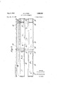
- FIGURE 11 is a front elevation of a part of a car supporting table for use with a lift mick showing the cantilever arms in an extended position
- FIGURE 12 is a plan of one side of the arrangement shown in FIGURE 11,
- FIGURE .13 is a similar view to FIGURE 11 showing one half of the assemblage with the cantilever arms in a retracted position
- FIGURE .14 is an end view of .a car-stacking structure and a side elevation of a fork lift truck according to the invention lifting a car,
- FIGURE 15 is a view looking from the right of FIG- URE 14; I
- FIGURE 16 is a similar view to FIGURE 14, butiii which the fork arms of the truck extend from the side thereof instead of from the end;
- FIGURE 17 is a view looking from the right of FIG URE 16.
- FIGURES 1 to 3 The construction shown in FIGURES 1 to 3 comprises a row of reinforced concrete pillars 10 which extend into and are wedged firmly in sockets 9 formed in the ground or in the floor of a building. At each of two levels on each pillar there extends on either side thereof cantilever arms 12 which may be formed from pro-stressed concrete or from ordinary reinforced concrete.
- the cantilevre arms are shown supported on abutments or brackets 13 which are cast on the pillars 10 and bolts may extend through holes formed in flanged portions 14 of the cantilever arm at a location indicated by the dotted lines '15, Preferably however the abutrnents or brackets 13 are dispensed with and the cantilever arms held in position by bolts passing through holes extending the whole length of the arms and through holes in the pillar.
- the upper surface of each cantilever arm may be provided with two spaced recesses 16 and 17 of appreciable width and located in these two recesses respectively are pre-stre's'sed reinforced concrete planks 18 and 19.
- planks are of such a length as to extend between cantilever arms of two or more adjacent pillars so as to be supported at their ends by about half the width of the cantilever arms.
- the recesses may be so shaped that the surfaces of the planks are inclined downwardly towards the space between them.
- the space is closed by a light sheet metal asbestos or concrete removable trough 20 which collects the drippings from the cars.
- Angle irons 21 are also secured to opposite sides of each pillar and extend between adjacent pillars, which angle irons support wood fenders 22 which are of such a width that When the Wheels of a car are in contact therewith the body of the car is spaced away from the pillars.
- each pillar may be provided with a photo electric cell 23 associated with a signal so that the operator is warned before the car body is dangerously close to a pillar.
- Each plilar may be provided at its upper end with an extension 24 to which is secured on either side thereof one extremity of a roof truss 25.
- a curb 26 is provided at ground level immediately below the ends of the cantilever arms so as to locate a lifting truck in an appropriate position for lifting a car on to a platform.
- the cantilevers at the ends of the row of pillars may be so shaped and dimensioned as to extend above the aforesaid planks so as to form a safety wall 34.
- a single cantilever arm 27 is provided which is either bolted by bolts 28 to a side face of the pillar or extends through a hole 29 precast in the pillar as shown in FIGURE 5, and held in position by bolts extending through holes in the pillar and through the cantilever arm and by wedges 30.
- the F pillars 10 are supported at their lower ends on suitable foundations 11 or rafts and are provided at different 3 levels with bracket portions 31 on opposite sides thereof from each of which two brackets extend a single length cantilever arm 32.
- the ends of the cantilever arms are connected together by cross members 35 and an I section member 36 is arranged to extend between adjacent pillars.
- Reinforced concrete panels or planks 37 are supported by each cross member 35 and a flange of the I section member 36 which planks are arranged side by side in contact therewith so as to form a continuous supporting surface for the cars.
- Guttering 38 may be arranged to extend along the outer edge of the concrete planks.
- the pillars 10 may be provided with extensions 24 for supporting a roof structure 25.
- two precast panels 39 which as will be seen from FIGURE 10 are arranged edge to edge and with adjacent edges extending in the direction between adjacent pillars.
- each panel along that edge which lies adjacent to a pillar has cast integrally with it a comparatively deep cross beam 42 which rests on an abutment 43 cast integrally with the pillars.
- the upper surface of each half panel may be so shaped that the inner and outer portions thereof are inclined downwardly towards one another and where they join a number of holes 46 are formed extending through the thickness of the panel and beneath the lower ends of which holes is provided a sheet metal drain 45.
- the upper surface of each panel may be provided with shallow scollops 47 as best indicated in FIGURE 10 which tend to prevent the vehicles from rolling along the panels should their brakes become released.
- each pillar may be provided with an extension 24 for supporting a roof structure 25.
- FIGURES 11 to 13 show a table suitable for supporting the wheels of cars and is arranged for attchment to a vertically moving part of a lift truck.
- the table comprises a central body 48 across which extend two tubular guides 49 and 50 so as to project from both sides of truck the ends of which guides are secured to members 51.
- Slidably mounted in the guides 49 are stout rods 52 which project respectively from opposite sides of the body part.
- stout rods 53 which likewise project respectively from opposite sides of the body part.
- the rods 52 and 53 are secured at opposite ends to members 54 and each of those members has secured to it a plunger 55 of a ram 9 which rams are fixed to the body part 48.
- Each member 54 has a downwardly extending arm 56 the lower extremity of which is provided with a forwardly extending cantilever arm 57.
- Each member 54 has also secured to it, forward of the rods 52 and 53, two other tubular guides 58 (only one of which is shown in FIG- URE l by the dotted lines) in which are mounted rods 59.
- Each rod 59 is connected at one end to a second downwardly extending arm 60 having a forwardly extending lever arm 61 at its lower end.
- a cylinder 62 of a second ram is attached to each member 54 and its ram 63 is secured to the arm 60.
- the spacing apart of the cantilever arms 57 and 61 can be adjusted in accordance with the sizes of the wheels of the car, and by energising the rams 9 the pairs of arms 57 and 61 can be moved towards and away from one another according to the wheel base of the vehicles, and when the apparatus is not in use, the pairs of lever arms can be brought close to the main body 48 as shown in FIGURE 13.
- the rams may be placed in communication with a source of fluid pressure through suitable control valves.
- the forwardly extending cantilever arms 57, 61 may be so constructed that they may be contracted or extended in relation to the members 54 and 60 which carry them thus enabling the truck with arms in a contracted condition to approach the side of the car whereafter the arms are extended on either side of each wheel.
- L contraction and extension of the arms may either be effected by hand or by suitable motors. With this arrangement the manoeuvring space required for a truck is reduced to a minimum.
- the aforesaid central body part 48 of the lifting table is mounted in known manner on the upright guides 64 fixed to the front of the fork lift truck 65, so that the body part 48 may be raised by suitable power means.
- the fork arms 57 and 61 project forwardly of the fork lift truck which, when a car is to be lifted, approaches the car from one side thereof so that one pair of fork arms 57 and 61 straddle a front wheel and the other pair 57, 61 straddle the back wheel.
- the rams 9 and 56 shown in FIGURE 11 are operated so that two pairs of fork arms are appropriately spaced apart for the wheel base of the car and the rams 62 are operated so that the fork arms are appropriately spaced apart, so as to to be capable of straddling the wheels.
- the body part 48 is raised and, if all the arms are not then in contact with the wheels, the aforesaid rams are again actuated.
- the body part 48 is then further raised until the wheels of the car are above the level of a selected supporting platform 66 of a parking structure, which may comprise a number of such platforms 66 fixed cantilever fashion to upright pillars 67.
- the fork lift truck then is brought into a position so that the car is disposed above a platform facing in a direction along the platform.
- the body part 48 is then lowered until the wheels of the car are supported on the platform whereupon the truck may be backed away from the structure, thus withdrawing the fork arms from beneath the wheels.
- the arrangement shown in FIGURES 16 and 17 is similar, except for the fact that the body part 48 and the upright guides 64 are disposed at the side of the truck and the fork arms extend from that side.
- a fork lift truck for lifting automobiles having different wheel bases and different-sized wheels comprising a lifting head, two pairs of forks spaced apart on said head and movable laterally with respect thereto, power means adapted to move the two pairs of fork arms towards and away from one another, and other power means for moving the two arms of each pair towards and away from one another, said power means comprising two hydraulic rams, each having a cylinder mounted across said lifting head, with the ram of each connected to an outermost fork arm, said other power means also comprising hydraulic rams, each including a cylinder connected to outer fork arms and a plunger connected to an inner fork arm.
- a fork lift truck for lifting automobiles having different wheel bases and different-sized wheels comprising a lifting head, two pairs of forks spaced apart on said head and movable laterally with respect thereto, power means adapted to move the two pairs of fork arms toward and away from one another, and other power means for moving the two arms of each pair towards and away from one another, said head being provided with guides, each extending on each side of the head, rods slidable in and extending outwardly from said guides, two structures on opposite sides of the head and connected to said rods and each having an outer fork arm secured thereto, said power means including two hydraulic ram cylinders mounted on said head and each having a plunger secured to one of said structures, said other power means also comprising hydraulic rams, each of said last mentioned rams including a cylinder fixed to one of said structures having a plunger connected to one of the inner fork arms, further guides being provided between the structures and the inner fork arms.
Landscapes
- Engineering & Computer Science (AREA)
- Architecture (AREA)
- Mechanical Engineering (AREA)
- Civil Engineering (AREA)
- Structural Engineering (AREA)
- Handcart (AREA)
Description
C. K. F ITCH CAR PARKING APPARATUS Aug. 8, 1961 9 Sheets-Sheet l Filed Nov. 22, 1955 mvEu-roR CLIFFORD K. F mm ATT RNEY-S 9 Sheets-Sheet 3 INVENTOR CLIFFORD K. Flmu Filgd Nov. 22, 1955 Aug. 8, 1961 c. K. FITCH 2,995,263
CAR PARKING APPARATUS Filed Nov. 22, 1955 9 Sheets-Sheet 4 i i lm ls m'on 4 CLIFFORD K. Fmzu olfazzw, M, M 9
HTTQ R N EYS Aug. 8, 1961 c. K. FITCH 2,995,263
CAR PARKING APPARATUS Filed Nov. 22, 1955 9 Sheets-Sheet 5 52 32 52 32 \p- H L H H fi 31 38 31 31 mVENToR CHI-FORD K. FrrcH 3 HTTO ENE V5 Aug. 8, 1961 c. K. FITCH CAR PARKING APPARATUS 9 Sheets-Sheet 6 Filed Nov. 22, 1955 WK H A m 9 m w/ "E C MW/ M %/L ME 3 44 m ha! A A] U HU L l /ll.L 5 A H 3 W 9 4. w/ 5 5 Mm 4 i w Mafia; lag, WWW M ATTORNEVS 9 Sheets-Sheet 8 mw, w mm mww wm m V M -HHnHHnu W m mmn m n u m n u n m ll hm A m HMHHHHHHIIIIIUII I'M U W m nul H| I'|| h lc I W 1961 c. K. FITCH CAR PARKING APPARATUS Filed NOV. 22, 1955 Aug. 8, 1961 c. K. FITCH CAR PARKING APPARATUS 9 Sheets-Sheet 9 Filed Nov. 22, 1955 R O T tar. mm 9 2. W EEK/V6??? vvvw 1 3 8 m a i E .I m .ww ww @W CLIFFORD K. FITCH BY 11/01:, (2, amazztm/azzm ATTORNEYS United States Patent 2,995,263 C'AR PARKING APPARATUS Clifford Kingsbury Fitch, 54 Braundton Ave., Sidcup, Kent, England Filed Nov. 22, 1955, Ser. No. 548,505 Claims priority, application Great Britain Mar. 2, 1955 2 claims. (Cl. 214-431) This invention relates to car parking apparatus and has for an object to provide a system which will enable cars to be readily stacked above one another in a comparatively confined space either in the open or in a building. The term car is intended to include land vehicles in general but the invention is particularly applicable to motor road vehicles.
A lift truck for use with a parking apparatus as first referred to may comprise a number of forwardly or laterally extending cantilever arms so arranged that one pair of arms may support the two front wheels or tyres of the car and another pair of arms may support the two back wheels or tyres.
Means may be provided for adjustably mounting the aforesaid pairs of cantilever arms on the lifting table so as to be movable towards and away from one another and so as to accommodate wheels or tyres of cars of different wheel bases and also so that when the truck is not in use the width of the lifting table may be reduced to a minimum. Also means may be provided for varying the spacing apart of cantilever arms in each pair so as to accommodate different sized wheels or tyres.
The following is a description of the invention reference being made to the accompanying drawings in which:
FIGURE 1 is an elevation of a car supporting struc- .ture adapted for use in conjunction with the fork lift truck of the invention, looking in the direction of a row of pillars, and also showing a part of the roof structure,
FIGURE 2 is an elevation looking from one side of FIGURE 1 showing part of the structure,
FIGURE 3 is a plan of a part of the structure shown in FIGURES 1 and 2,
FIGURE 4 is a similar view to FIGURE 1 of a part of an alternative construction,
FIGURE 5 is a view looking from one side of FIG- URE 4,
FIGURE 6 is also a similar view toFlGURE 1, of yet a further alternative construction,
FIGURE 7 is a view looking from one side of FIG- URE 6,
FIGURE 8 is a similar view'to FIG-URE 1 of yet a further alternative form of construction,
FIGURE 9 is a view looking from one side of FIG- URE 8,
FIGURE 10 is a plan view of the arrangement in FIG- URE 9,
FIGURE 11 is a front elevation of a part of a car supporting table for use with a lift mick showing the cantilever arms in an extended position,
FIGURE 12 is a plan of one side of the arrangement shown in FIGURE 11,
FIGURE .13 is a similar view to FIGURE 11 showing one half of the assemblage with the cantilever arms in a retracted position,
FIGURE .14 is an end view of .a car-stacking structure and a side elevation of a fork lift truck according to the invention lifting a car,
ice
FIGURE 15 is a view looking from the right of FIG- URE 14; I
FIGURE 16 is a similar view to FIGURE 14, butiii which the fork arms of the truck extend from the side thereof instead of from the end; and
FIGURE 17 is a view looking from the right of FIG URE 16.
The construction shown in FIGURES 1 to 3 comprises a row of reinforced concrete pillars 10 which extend into and are wedged firmly in sockets 9 formed in the ground or in the floor of a building. At each of two levels on each pillar there extends on either side thereof cantilever arms 12 which may be formed from pro-stressed concrete or from ordinary reinforced concrete. The cantilevre arms are shown supported on abutments or brackets 13 which are cast on the pillars 10 and bolts may extend through holes formed in flanged portions 14 of the cantilever arm at a location indicated by the dotted lines '15, Preferably however the abutrnents or brackets 13 are dispensed with and the cantilever arms held in position by bolts passing through holes extending the whole length of the arms and through holes in the pillar. The upper surface of each cantilever arm may be provided with two spaced recesses 16 and 17 of appreciable width and located in these two recesses respectively are pre-stre's'sed reinforced concrete planks 18 and 19. These planks are of such a length as to extend between cantilever arms of two or more adjacent pillars so as to be supported at their ends by about half the width of the cantilever arms. The recesses may be so shaped that the surfaces of the planks are inclined downwardly towards the space between them. The space is closed by a light sheet metal asbestos or concrete removable trough 20 which collects the drippings from the cars. Angle irons 21 are also secured to opposite sides of each pillar and extend between adjacent pillars, which angle irons support wood fenders 22 which are of such a width that When the Wheels of a car are in contact therewith the body of the car is spaced away from the pillars. Alternatively or additionally each pillar may be provided with a photo electric cell 23 associated with a signal so that the operator is warned before the car body is dangerously close to a pillar. Each plilar may be provided at its upper end with an extension 24 to which is secured on either side thereof one extremity of a roof truss 25. A curb 26 is provided at ground level immediately below the ends of the cantilever arms so as to locate a lifting truck in an appropriate position for lifting a car on to a platform.
The outer edges of the pre-stressed concrete planks .are protected by channel section nose pieces 33.
The cantilevers at the ends of the row of pillars may be so shaped and dimensioned as to extend above the aforesaid planks so as to form a safety wall 34.
In the arrangement shown in FIGURES 4 and 5 instead of two cantilever arms being provided at each level on a pillar, a single cantilever arm 27 is provided which is either bolted by bolts 28 to a side face of the pillar or extends through a hole 29 precast in the pillar as shown in FIGURE 5, and held in position by bolts extending through holes in the pillar and through the cantilever arm and by wedges 30.
In the construction shown in FIGURES 6 and 7 the F pillars 10 are supported at their lower ends on suitable foundations 11 or rafts and are provided at different 3 levels with bracket portions 31 on opposite sides thereof from each of which two brackets extend a single length cantilever arm 32.
The ends of the cantilever arms are connected together by cross members 35 and an I section member 36 is arranged to extend between adjacent pillars. Reinforced concrete panels or planks 37 are supported by each cross member 35 and a flange of the I section member 36 which planks are arranged side by side in contact therewith so as to form a continuous supporting surface for the cars. Guttering 38 may be arranged to extend along the outer edge of the concrete planks. As in the previous construction the pillars 10 may be provided with extensions 24 for supporting a roof structure 25. In the construction shown in FIGURES 8 to 10 thereare provided at each level on each pillar two precast panels 39 which as will be seen from FIGURE 10 are arranged edge to edge and with adjacent edges extending in the direction between adjacent pillars. The edges are recessed at 40 to accommodate the pillars. Each panel along that edge which lies adjacent to a pillar has cast integrally with it a comparatively deep cross beam 42 which rests on an abutment 43 cast integrally with the pillars. The upper surface of each half panel may be so shaped that the inner and outer portions thereof are inclined downwardly towards one another and where they join a number of holes 46 are formed extending through the thickness of the panel and beneath the lower ends of which holes is provided a sheet metal drain 45. The upper surface of each panel may be provided with shallow scollops 47 as best indicated in FIGURE 10 which tend to prevent the vehicles from rolling along the panels should their brakes become released. As previously indicated each pillar may be provided with an extension 24 for supporting a roof structure 25.
FIGURES 11 to 13 show a table suitable for supporting the wheels of cars and is arranged for attchment to a vertically moving part of a lift truck. The table comprises a central body 48 across which extend two tubular guides 49 and 50 so as to project from both sides of truck the ends of which guides are secured to members 51. Slidably mounted in the guides 49 are stout rods 52 which project respectively from opposite sides of the body part. In the other guides 50 are slidably mounted stout rods 53 which likewise project respectively from opposite sides of the body part. The rods 52 and 53 are secured at opposite ends to members 54 and each of those members has secured to it a plunger 55 of a ram 9 which rams are fixed to the body part 48. Each member 54 has a downwardly extending arm 56 the lower extremity of which is provided with a forwardly extending cantilever arm 57. Each member 54 has also secured to it, forward of the rods 52 and 53, two other tubular guides 58 (only one of which is shown in FIG- URE l by the dotted lines) in which are mounted rods 59. Each rod 59 is connected at one end to a second downwardly extending arm 60 having a forwardly extending lever arm 61 at its lower end. A cylinder 62 of a second ram is attached to each member 54 and its ram 63 is secured to the arm 60. Thus by energising the hydraulic rams 62 the spacing apart of the cantilever arms 57 and 61 can be adjusted in accordance with the sizes of the wheels of the car, and by energising the rams 9 the pairs of arms 57 and 61 can be moved towards and away from one another according to the wheel base of the vehicles, and when the apparatus is not in use, the pairs of lever arms can be brought close to the main body 48 as shown in FIGURE 13. The rams may be placed in communication with a source of fluid pressure through suitable control valves.
The forwardly extending cantilever arms 57, 61 may be so constructed that they may be contracted or extended in relation to the members 54 and 60 which carry them thus enabling the truck with arms in a contracted condition to approach the side of the car whereafter the arms are extended on either side of each wheel. The
L contraction and extension of the arms may either be effected by hand or by suitable motors. With this arrangement the manoeuvring space required for a truck is reduced to a minimum. Referring to FIGURES l4 and 15, the aforesaid central body part 48 of the lifting table is mounted in known manner on the upright guides 64 fixed to the front of the fork lift truck 65, so that the body part 48 may be raised by suitable power means. In this arrangement, the fork arms 57 and 61 project forwardly of the fork lift truck which, when a car is to be lifted, approaches the car from one side thereof so that one pair of fork arms 57 and 61 straddle a front wheel and the other pair 57, 61 straddle the back wheel. Before approaching the car, the rams 9 and 56 shown in FIGURE 11 are operated so that two pairs of fork arms are appropriately spaced apart for the wheel base of the car and the rams 62 are operated so that the fork arms are appropriately spaced apart, so as to to be capable of straddling the wheels. After the arms have been inserted beneath the wheels, the body part 48 is raised and, if all the arms are not then in contact with the wheels, the aforesaid rams are again actuated. The body part 48 is then further raised until the wheels of the car are above the level of a selected supporting platform 66 of a parking structure, which may comprise a number of such platforms 66 fixed cantilever fashion to upright pillars 67. The fork lift truck then is brought into a position so that the car is disposed above a platform facing in a direction along the platform. The body part 48 is then lowered until the wheels of the car are supported on the platform whereupon the truck may be backed away from the structure, thus withdrawing the fork arms from beneath the wheels. The arrangement shown in FIGURES 16 and 17 is similar, except for the fact that the body part 48 and the upright guides 64 are disposed at the side of the truck and the fork arms extend from that side.
I claim:
1. A fork lift truck for lifting automobiles having different wheel bases and different-sized wheels, comprising a lifting head, two pairs of forks spaced apart on said head and movable laterally with respect thereto, power means adapted to move the two pairs of fork arms towards and away from one another, and other power means for moving the two arms of each pair towards and away from one another, said power means comprising two hydraulic rams, each having a cylinder mounted across said lifting head, with the ram of each connected to an outermost fork arm, said other power means also comprising hydraulic rams, each including a cylinder connected to outer fork arms and a plunger connected to an inner fork arm.
2. A fork lift truck for lifting automobiles having different wheel bases and different-sized wheels, comprising a lifting head, two pairs of forks spaced apart on said head and movable laterally with respect thereto, power means adapted to move the two pairs of fork arms toward and away from one another, and other power means for moving the two arms of each pair towards and away from one another, said head being provided with guides, each extending on each side of the head, rods slidable in and extending outwardly from said guides, two structures on opposite sides of the head and connected to said rods and each having an outer fork arm secured thereto, said power means including two hydraulic ram cylinders mounted on said head and each having a plunger secured to one of said structures, said other power means also comprising hydraulic rams, each of said last mentioned rams including a cylinder fixed to one of said structures having a plunger connected to one of the inner fork arms, further guides being provided between the structures and the inner fork arms.
(References on following page) 5 References Cited in the file of this patent UNITED STATES PATENTS Burgess Feb. 22, 1921 Been Aug. 30, 1932 5 Bratley July 20, 1943 Olson Feb. 24, 1953 Alimanestiano Aug. 4, 1953 Cartlidge Apr. 6, 1954 Evans Feb. 7, 1956 Held *et a1. Mar. 6, 1956 Riernenschneider Oct. 9, 1956 West et 211. Dec. 11, 1956 6 Overlach et a1. July 30, 1957 Miller Aug. 12, 1958 FOREIGN PATENTS Switzerland May 16, 1952 Switzerland May 2, 1955 OTHER REFERENCES Publication, Meehancix Illustrated, October 1952,
page 89.
(page 5).
Applications Claiming Priority (1)
| Application Number | Priority Date | Filing Date | Title |
|---|---|---|---|
| GB2995263X | 1955-03-02 |
Publications (1)
| Publication Number | Publication Date |
|---|---|
| US2995263A true US2995263A (en) | 1961-08-08 |
Family
ID=10919393
Family Applications (1)
| Application Number | Title | Priority Date | Filing Date |
|---|---|---|---|
| US548505A Expired - Lifetime US2995263A (en) | 1955-03-02 | 1955-11-22 | Car parking apparatus |
Country Status (1)
| Country | Link |
|---|---|
| US (1) | US2995263A (en) |
Cited By (13)
| Publication number | Priority date | Publication date | Assignee | Title |
|---|---|---|---|---|
| US3231109A (en) * | 1957-04-26 | 1966-01-25 | Irion & Vosseler | Material handling machine |
| US3416685A (en) * | 1967-12-12 | 1968-12-17 | Speed Park Inc | Transfer device with independently movable load supporting means |
| US3448874A (en) * | 1967-07-03 | 1969-06-10 | Koehring Co | Mobile crane with spaced pivotally mounted booms |
| US3684113A (en) * | 1970-06-12 | 1972-08-15 | Skagit Corp | Dunnage clamp for forklift trucks |
| JPS4851081U (en) * | 1971-10-15 | 1973-07-03 | ||
| US3977542A (en) * | 1973-07-26 | 1976-08-31 | Stopa Stahlbau Gmbh & Co. Kommanditgesellschaft Fur Schweisstechnik | Storage frames with deflection bar to pivot tines on a gantry |
| US4016987A (en) * | 1974-05-31 | 1977-04-12 | Stopa Stahlbau Gmbh & Co. | Storage system |
| US4073394A (en) * | 1976-01-06 | 1978-02-14 | Southern Pacific Transportation Company | Lift truck with attachment for carrying automobiles |
| US5067869A (en) * | 1990-04-17 | 1991-11-26 | Reuss George F | Automobile transportation apparatus |
| US5139385A (en) * | 1990-04-03 | 1992-08-18 | Swingshift Manufacturing, Inc. | Dual pallet fork attachment for a lift truck |
| DE4223646A1 (en) * | 1991-07-19 | 1993-02-04 | Nippon Kokan Kk | DEVICE FOR TRANSPORTING A MOTOR VEHICLE AND MULTI-STOREY PARKING HOUSE |
| US5286156A (en) * | 1992-06-19 | 1994-02-15 | Nkk Corporation | Apparatus for transferring a motor vehicle in a multistory parking lot |
| US20170211287A1 (en) * | 2016-01-21 | 2017-07-27 | Dpg Deutsche Parken Gmbh | Parking garage for motor vehicles, in particular multistory parking garage, and method for manufacturing a parking garage |
Citations (14)
| Publication number | Priority date | Publication date | Assignee | Title |
|---|---|---|---|---|
| US1369393A (en) * | 1919-02-11 | 1921-02-22 | Smith Corp A O | Storage-building and hoist |
| US1874859A (en) * | 1930-06-18 | 1932-08-30 | Harnischfeger Corp | Apparatus for handling and storing |
| US2324817A (en) * | 1941-07-12 | 1943-07-20 | Morris Ltd Herbert | Traverser |
| CH281000A (en) * | 1949-12-22 | 1952-02-15 | Ag Ard | Method for parking goods, in particular for parking vehicles, and device for carrying out the method. |
| US2629507A (en) * | 1946-07-29 | 1953-02-24 | Olson Oscar Jelmer | Car parking mechanism |
| US2647647A (en) * | 1949-06-03 | 1953-08-04 | Cornelius Kroll | Apparatus for parking automobiles |
| US2674364A (en) * | 1950-12-30 | 1954-04-06 | Goodman Mfg Co | Portable conveying apparatus |
| CH305594A (en) * | 1951-11-06 | 1955-02-28 | Ag Sicomatic | Device for stationing by stacking vehicles in adjacent and stacked building-like combined cells which are open at least on one side |
| US2733825A (en) * | 1956-02-07 | evans | ||
| US2737303A (en) * | 1953-01-09 | 1956-03-06 | Western Electric Co | Cable reel tiering truck |
| US2765928A (en) * | 1950-10-18 | 1956-10-09 | Claud C Riemenschneider | Merchandise handling and storing equipment |
| US2773612A (en) * | 1953-06-30 | 1956-12-11 | Lukens Steel Co | Apparatus for loading and unloading trailers and the like onto and from platforms and the like |
| US2801011A (en) * | 1953-08-03 | 1957-07-30 | Overlach Hans | Gripping truck |
| US2847131A (en) * | 1950-01-17 | 1958-08-12 | Miller Leona Nell | Automobile storage |
-
1955
- 1955-11-22 US US548505A patent/US2995263A/en not_active Expired - Lifetime
Patent Citations (14)
| Publication number | Priority date | Publication date | Assignee | Title |
|---|---|---|---|---|
| US2733825A (en) * | 1956-02-07 | evans | ||
| US1369393A (en) * | 1919-02-11 | 1921-02-22 | Smith Corp A O | Storage-building and hoist |
| US1874859A (en) * | 1930-06-18 | 1932-08-30 | Harnischfeger Corp | Apparatus for handling and storing |
| US2324817A (en) * | 1941-07-12 | 1943-07-20 | Morris Ltd Herbert | Traverser |
| US2629507A (en) * | 1946-07-29 | 1953-02-24 | Olson Oscar Jelmer | Car parking mechanism |
| US2647647A (en) * | 1949-06-03 | 1953-08-04 | Cornelius Kroll | Apparatus for parking automobiles |
| CH281000A (en) * | 1949-12-22 | 1952-02-15 | Ag Ard | Method for parking goods, in particular for parking vehicles, and device for carrying out the method. |
| US2847131A (en) * | 1950-01-17 | 1958-08-12 | Miller Leona Nell | Automobile storage |
| US2765928A (en) * | 1950-10-18 | 1956-10-09 | Claud C Riemenschneider | Merchandise handling and storing equipment |
| US2674364A (en) * | 1950-12-30 | 1954-04-06 | Goodman Mfg Co | Portable conveying apparatus |
| CH305594A (en) * | 1951-11-06 | 1955-02-28 | Ag Sicomatic | Device for stationing by stacking vehicles in adjacent and stacked building-like combined cells which are open at least on one side |
| US2737303A (en) * | 1953-01-09 | 1956-03-06 | Western Electric Co | Cable reel tiering truck |
| US2773612A (en) * | 1953-06-30 | 1956-12-11 | Lukens Steel Co | Apparatus for loading and unloading trailers and the like onto and from platforms and the like |
| US2801011A (en) * | 1953-08-03 | 1957-07-30 | Overlach Hans | Gripping truck |
Cited By (15)
| Publication number | Priority date | Publication date | Assignee | Title |
|---|---|---|---|---|
| US3231109A (en) * | 1957-04-26 | 1966-01-25 | Irion & Vosseler | Material handling machine |
| US3448874A (en) * | 1967-07-03 | 1969-06-10 | Koehring Co | Mobile crane with spaced pivotally mounted booms |
| US3416685A (en) * | 1967-12-12 | 1968-12-17 | Speed Park Inc | Transfer device with independently movable load supporting means |
| US3684113A (en) * | 1970-06-12 | 1972-08-15 | Skagit Corp | Dunnage clamp for forklift trucks |
| JPS4851081U (en) * | 1971-10-15 | 1973-07-03 | ||
| US3977542A (en) * | 1973-07-26 | 1976-08-31 | Stopa Stahlbau Gmbh & Co. Kommanditgesellschaft Fur Schweisstechnik | Storage frames with deflection bar to pivot tines on a gantry |
| US4016987A (en) * | 1974-05-31 | 1977-04-12 | Stopa Stahlbau Gmbh & Co. | Storage system |
| US4073394A (en) * | 1976-01-06 | 1978-02-14 | Southern Pacific Transportation Company | Lift truck with attachment for carrying automobiles |
| US5139385A (en) * | 1990-04-03 | 1992-08-18 | Swingshift Manufacturing, Inc. | Dual pallet fork attachment for a lift truck |
| US5067869A (en) * | 1990-04-17 | 1991-11-26 | Reuss George F | Automobile transportation apparatus |
| DE4223646A1 (en) * | 1991-07-19 | 1993-02-04 | Nippon Kokan Kk | DEVICE FOR TRANSPORTING A MOTOR VEHICLE AND MULTI-STOREY PARKING HOUSE |
| US5292218A (en) * | 1991-07-19 | 1994-03-08 | Nkk Corporation | Apparatus for transferring a motor vehicle and multistory parking lot |
| US5286156A (en) * | 1992-06-19 | 1994-02-15 | Nkk Corporation | Apparatus for transferring a motor vehicle in a multistory parking lot |
| US20170211287A1 (en) * | 2016-01-21 | 2017-07-27 | Dpg Deutsche Parken Gmbh | Parking garage for motor vehicles, in particular multistory parking garage, and method for manufacturing a parking garage |
| US10738496B2 (en) * | 2016-01-21 | 2020-08-11 | Dpg Deutsche Parken Gmbh | Parking garage for motor vehicles, in particular multistory parking garage, and method for manufacturing a parking garage |
Similar Documents
| Publication | Publication Date | Title |
|---|---|---|
| US2995263A (en) | Car parking apparatus | |
| US3888100A (en) | Auto body and frame straightening devices | |
| US9132871B2 (en) | Low profile walking machine and method of operation | |
| US2639450A (en) | Dock loading ramp unit | |
| US3866530A (en) | Apparatus for fabricating wood structures | |
| GB1050180A (en) | ||
| US4050707A (en) | Liftable bed truck body configuration for removable storage unit | |
| US3079015A (en) | Automobile parking apparatus | |
| US4209276A (en) | Vehicle parking apparatus | |
| US20130104322A1 (en) | Movable Vehicle Roof Sweeper | |
| US3804206A (en) | Ramp hoist | |
| US2733825A (en) | evans | |
| US3415342A (en) | Vehicle lifting apparatus | |
| USRE31636E (en) | Auto body and frame straightening device | |
| US4285374A (en) | Mobile wood splitter | |
| US3409923A (en) | Adjustable platform and ramp unit | |
| US3338334A (en) | Vehicle lift | |
| US3258135A (en) | Apparatus for transporting and handling large tubular structural sections | |
| US3960282A (en) | Car parking structure with a car lift at the entrance thereof | |
| JP2898492B2 (en) | Undercarriage trolley and culvert installation method | |
| US3347342A (en) | Lift installation | |
| JP4054469B2 (en) | Protector moving method and protector | |
| US2690235A (en) | Adjustable axle support for automobile lifts | |
| US2991725A (en) | Railway tie spacer | |
| US3432006A (en) | Hydraulic hoist for motor vehicles |