US2995201A - Safety control system - Google Patents
Safety control system Download PDFInfo
- Publication number
- US2995201A US2995201A US754887A US75488758A US2995201A US 2995201 A US2995201 A US 2995201A US 754887 A US754887 A US 754887A US 75488758 A US75488758 A US 75488758A US 2995201 A US2995201 A US 2995201A
- Authority
- US
- United States
- Prior art keywords
- burner
- valve
- compartment
- liquid
- conduit
- Prior art date
- Legal status (The legal status is an assumption and is not a legal conclusion. Google has not performed a legal analysis and makes no representation as to the accuracy of the status listed.)
- Expired - Lifetime
Links
- 239000007788 liquid Substances 0.000 description 77
- 239000007789 gas Substances 0.000 description 32
- 238000000034 method Methods 0.000 description 25
- 230000008569 process Effects 0.000 description 25
- 239000002737 fuel gas Substances 0.000 description 18
- 239000012530 fluid Substances 0.000 description 16
- 238000002955 isolation Methods 0.000 description 8
- 238000002485 combustion reaction Methods 0.000 description 7
- 239000000446 fuel Substances 0.000 description 6
- 239000007791 liquid phase Substances 0.000 description 6
- 239000012808 vapor phase Substances 0.000 description 5
- 230000008901 benefit Effects 0.000 description 4
- 230000001105 regulatory effect Effects 0.000 description 4
- 230000004044 response Effects 0.000 description 4
- 230000000630 rising effect Effects 0.000 description 4
- 238000004891 communication Methods 0.000 description 3
- 239000007792 gaseous phase Substances 0.000 description 3
- 230000007257 malfunction Effects 0.000 description 3
- 238000012856 packing Methods 0.000 description 3
- 230000032258 transport Effects 0.000 description 3
- 241000364021 Tulsa Species 0.000 description 2
- 230000001276 controlling effect Effects 0.000 description 2
- 239000000839 emulsion Substances 0.000 description 2
- 231100001261 hazardous Toxicity 0.000 description 2
- 238000007689 inspection Methods 0.000 description 2
- 230000007246 mechanism Effects 0.000 description 2
- 239000003129 oil well Substances 0.000 description 2
- 239000000047 product Substances 0.000 description 2
- 230000008439 repair process Effects 0.000 description 2
- 238000009825 accumulation Methods 0.000 description 1
- 239000006227 byproduct Substances 0.000 description 1
- 230000015556 catabolic process Effects 0.000 description 1
- 238000007599 discharging Methods 0.000 description 1
- 238000010438 heat treatment Methods 0.000 description 1
- 229930195733 hydrocarbon Natural products 0.000 description 1
- 150000002430 hydrocarbons Chemical class 0.000 description 1
- 238000004519 manufacturing process Methods 0.000 description 1
- 239000000463 material Substances 0.000 description 1
- 230000004048 modification Effects 0.000 description 1
- 238000012986 modification Methods 0.000 description 1
- 230000000644 propagated effect Effects 0.000 description 1
- 239000007787 solid Substances 0.000 description 1
- 238000012546 transfer Methods 0.000 description 1
- 239000002699 waste material Substances 0.000 description 1
- XLYOFNOQVPJJNP-UHFFFAOYSA-N water Substances O XLYOFNOQVPJJNP-UHFFFAOYSA-N 0.000 description 1
- 239000002569 water oil cream Substances 0.000 description 1
Images


Classifications
-
- F—MECHANICAL ENGINEERING; LIGHTING; HEATING; WEAPONS; BLASTING
- F23—COMBUSTION APPARATUS; COMBUSTION PROCESSES
- F23N—REGULATING OR CONTROLLING COMBUSTION
- F23N5/00—Systems for controlling combustion
- F23N5/24—Preventing development of abnormal or undesired conditions, i.e. safety arrangements
-
- F—MECHANICAL ENGINEERING; LIGHTING; HEATING; WEAPONS; BLASTING
- F23—COMBUSTION APPARATUS; COMBUSTION PROCESSES
- F23N—REGULATING OR CONTROLLING COMBUSTION
- F23N2239/00—Fuels
- F23N2239/06—Liquid fuels
-
- Y—GENERAL TAGGING OF NEW TECHNOLOGICAL DEVELOPMENTS; GENERAL TAGGING OF CROSS-SECTIONAL TECHNOLOGIES SPANNING OVER SEVERAL SECTIONS OF THE IPC; TECHNICAL SUBJECTS COVERED BY FORMER USPC CROSS-REFERENCE ART COLLECTIONS [XRACs] AND DIGESTS
- Y10—TECHNICAL SUBJECTS COVERED BY FORMER USPC
- Y10T—TECHNICAL SUBJECTS COVERED BY FORMER US CLASSIFICATION
- Y10T137/00—Fluid handling
- Y10T137/2931—Diverse fluid containing pressure systems
- Y10T137/3003—Fluid separating traps or vents
- Y10T137/3021—Discriminating outlet for liquid
- Y10T137/304—With fluid responsive valve
- Y10T137/3052—Level responsive
- Y10T137/3068—Float
- Y10T137/3071—With main line gas outlet from trap chamber
-
- Y—GENERAL TAGGING OF NEW TECHNOLOGICAL DEVELOPMENTS; GENERAL TAGGING OF CROSS-SECTIONAL TECHNOLOGIES SPANNING OVER SEVERAL SECTIONS OF THE IPC; TECHNICAL SUBJECTS COVERED BY FORMER USPC CROSS-REFERENCE ART COLLECTIONS [XRACs] AND DIGESTS
- Y10—TECHNICAL SUBJECTS COVERED BY FORMER USPC
- Y10T—TECHNICAL SUBJECTS COVERED BY FORMER US CLASSIFICATION
- Y10T137/00—Fluid handling
- Y10T137/2931—Diverse fluid containing pressure systems
- Y10T137/3003—Fluid separating traps or vents
- Y10T137/3021—Discriminating outlet for liquid
- Y10T137/304—With fluid responsive valve
- Y10T137/3052—Level responsive
- Y10T137/3068—Float
- Y10T137/3077—Servo-control
-
- Y—GENERAL TAGGING OF NEW TECHNOLOGICAL DEVELOPMENTS; GENERAL TAGGING OF CROSS-SECTIONAL TECHNOLOGIES SPANNING OVER SEVERAL SECTIONS OF THE IPC; TECHNICAL SUBJECTS COVERED BY FORMER USPC CROSS-REFERENCE ART COLLECTIONS [XRACs] AND DIGESTS
- Y10—TECHNICAL SUBJECTS COVERED BY FORMER USPC
- Y10T—TECHNICAL SUBJECTS COVERED BY FORMER US CLASSIFICATION
- Y10T137/00—Fluid handling
- Y10T137/2931—Diverse fluid containing pressure systems
- Y10T137/3003—Fluid separating traps or vents
- Y10T137/3084—Discriminating outlet for gas
- Y10T137/309—Fluid sensing valve
- Y10T137/3099—Float responsive
-
- Y—GENERAL TAGGING OF NEW TECHNOLOGICAL DEVELOPMENTS; GENERAL TAGGING OF CROSS-SECTIONAL TECHNOLOGIES SPANNING OVER SEVERAL SECTIONS OF THE IPC; TECHNICAL SUBJECTS COVERED BY FORMER USPC CROSS-REFERENCE ART COLLECTIONS [XRACs] AND DIGESTS
- Y10—TECHNICAL SUBJECTS COVERED BY FORMER USPC
- Y10T—TECHNICAL SUBJECTS COVERED BY FORMER US CLASSIFICATION
- Y10T137/00—Fluid handling
- Y10T137/4673—Plural tanks or compartments with parallel flow
Definitions
- the present invention relates to a control system for fuel to a burner. More specifically, the invention relates to a control system for fuel to a burner which is responsive to a plurality of malfunctions and which is manually reset for normal operation of the control system.
- Heat is often provided with a burner which consumes gas as fuel.
- the process may produce the fuel gas as a by-product, or a separate source of fuel gas may be avail-able.
- a hazard always results from any inflammable liquid associated with the gas being carried over to the burner.
- a mechanical failure of the burner compartment walls may permit liquids of the process to enter the compartment and create a hazard.
- Another object is to interlock the responses of the system to both liquids so the response of the system to one liquid collection is controlled by the response of the system to the other liquid collection.
- Another object is to require manual resetting of the system to supply fuel gas to the burner in a normal manner following response of the system to a malfunction which has caused isolation of fuel gas from the burner.
- the present invention contemplates a burner supplying heat to a process.
- the process utilizes liquids which would be a hazard in the burner compartment.
- Separate compartments are adapted to receive the hazardous liquids in order to make their predetermined quantities effective to isolate a gaseous fuel to the burner which passes through one of the compartments.
- the invention further contemplates primary elements in the compartments modifying control fluid pressures in accordance with liquid levels in the compartments.
- the fluid pressures modified by the primary elements are routed through the elements in series in order that one modification will depend on the other.
- the invention further contemplates that at least one of the primary elements will be provided with a structural arrangement which will modify the control fluid pressure output of the element when a predetermined level of liquid in the compartment is reached but which will prevent automatic restoration of the normal position of the element when the liquid level is lowered. Restoration of the normal output of the element is obtained by manual resetting of the structure of the primary element.
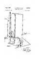
- FIG. 1 is a perspective of a treater for oil well production utilizing a portion of the gas produced for the burner system embodying the present invention
- FIG. 2 is a partially sectioned perspective of the burner ofthe treater of FIG. 1;
- FIG. 3 is a partially sectioned elevation of part of the system embodying the invention as illustrated in FIG. 1;
- FIG. 4 is a sectioned isometric view of a level responsive device of the structure of FIG. 3;
- FIG. 5 is a sectioned isometric view, partially exploded
- FIG. 1 a system embodying the invention is illustrated in association with an oil well treater.
- the treater shell is generally indicated at 1, being of the vertical type.
- the process carried on within the treater is illustrative of many processes requiring heat.
- treater 1 heat is used in treater 1 to break the emulsion between oil and water as it is produced by a well.
- the well stream is indicated as entering the shell of treater 1 through conduit 2.
- treater 1 There are many well-known arrangements which may be provided for the treater which will divide the well stream of inlet 2 into its components. Specific internal arrangements of treater 1 are not presently considered.
- clean oil produced by the process is passed out of the treater through conduit 3.
- the gas evolved from the process is passed out through conduit 4.
- Both the clean oil of conduit 3 and the gas of conduit 4 are products which can be sold.
- a portion of the gas of conduit 4, however, can be used to provide the necessary source of heat for the process in treater 1.
- FIG. 1 is illustrated with a heat source using a part of the gas of conduit 4.
- This heat source is specifically a direct-fired, return-tube, heater shown generally at 5, in the lower portion of the shell of treater l.
- the return-tube heater is illustrated in greater detail with FIG. 2.
- FIG. 2 shows the two legs of return-tube 6 extending into the shell of treater 1 and held in position by a bolted flange.
- the lower leg of tube 6 has a burner front 7 which controls the entry of combustion-supporting air and physically supports burner 8 and pilot 9.
- burner 8 comprises a mixing section and a tip section at which the combustion takes place.
- the assembly of sections is held in a fixed position within the lower leg of tube 6 by a set screw in the burner front 7 and a supporting bracket within the lower leg.
- the burner is supplied fuel gas through a manifold pipe 10.
- Pilot 9 is, essentially, a small burner which is supported in position solely by attachment to the burner front. Pilot 9 is supplied fuel gas by a pipe '11.
- pilot 9 is lit by pilot 9, the flame propagated produces prod nets of combustion which travel through tube 6 and transfer their heat to the contents of the shell of treater 1. The products of combustion then pass up stack '12 for discharge to the atmosphere.
- Stack 12 is attached to the upper end of tube 6 through stack breeching 13 bolted to the upper leg of tube 6.
- 'It is the system supplying fuel gas to burner 8 and pilot 9 with which the present invention is concerned. Additionally, it is the system arranged to respond to liquid of the process entering tube 6 and carried over with the fuel gas which embodies the present invention.
- the present invention specifically contemplates that liquid will be carried along with fuel gas to be supplied the burner 8 and pilot 9. Additionally, the invention contemplates that the tube 6 may fracture, or breakdown in some way, so liquid of the process will enter it. Either the liquid carried over with the gas, or the liquid entering a fracture may overflow tube 6. This liquid which overflows tube 6 may well be inflammable. If the liquid is discharged in sufiicient quantities it may well be ignited by the burner or pilot in the tube 6 or flood to an adjacent source of combustion which will ignite the overflowed liquid and destroy treater 1 and other property. Therefore, separate compartments are adapted to receive the hazardous liquids, and responsive elements within the compartments are interlocked in order to make predetermined quantities of the liquids effective to isolate the gaseous fuel from burner 8 and pilot 9 until the malfunctions are corrected.
- gas conduit 4 is shown as including a conventional back pressure valve 15 which maintains predetermined pressure on the process of the treater.
- Conduit 4 is shown as conducting the gas from the process for sale or remote use.
- Conduit 16 is connected into gas conduit 4 for removing a portion of the gas for use by burner 8 and pilot 9.
- a hand operated valve 17 is shown as providing isolation for the system of the burner when desired.
- Conduit 4, and conduit 16 may receive liquid carried over from the process of treater 1. This liquid may be mechanically carried over from the process or it may be partially condensed hydrocarbons as conduit 4 is cooled by contact with the atmosphere. In either event, it is desirable to isolate this liquid from burner 8 and pilot 9.
- a compartment is provided to receive all of the contents of conduit -16 and to separate the vapor phase from the liquid phase. The liquid phase is normally discharged from the compartment, perhaps to waste, and the vapor phase is taken to burner 8 and pilot 9 for combustion in tube 6.
- Provisions are made to discharge the liquid phase from the compartment while the vapor phase is supplied to the burner and pilot. It is customary to provide for the emergency condition where the liquid phase level builds up past the normal capacity of the removal means. It is customary to provide a simple float which will respond to a rising level of liquid in the compartment to actuate a valve which will isolate the burner and pilot from the vessel and thereby positively prevent the carryover liquid reaching the burner and pilot.
- conduit 18 which transports any liquids entering return tube 6 to a second compartment.
- a float is provided for this second compartment to respond to rising levels of liquid and control the isolation of the first compartment from the burner and pilot.
- the present invention contemplates control of the supply of fuel gas to the burner and pilot by both the liquid carried over with the gas and the liquid entering the burner compartment.
- the invention further contemplates the impulses developed by both floats in both compartments being so interconnected, in series, as to depend upon each other in controlling the flow of gas to the burner and pilot.
- the level-responsive mechanism of the first compartment is arranged to automatically restore communication between the vapor phase passing through the compartment and the burner and pilot. That is, when the level of liquid in the first compartment lowers to the extent which will insure none will be carried over to the tube 6, communication between the vapor phase and the burner and pilot will be automatically restored.
- the present invention contemplates, however, that any failure of tube 6 which permits liquids to enter it must be corrected manually. Therefore, liquids entering the second compartment, through conduit 18, will actuate the level-responsive means in a manner that will require manual restoration of normal operation. This arrangement permits actual inspection and repair of tube 6 before fuel gas is again provided for the burner and pilot through the first compartment.
- FIG. 1 The compartments are illustrated in FIG. 1 as provided by a unitary vessel 19.
- Conduit 16 is connected into the first, or top, compartment of vessel 19 and manifold is also connected into this first compartment.
- Conduit 18 is connected into the lower, or second, compartment of vessel 19. Liquids from the top compartment are automatically withdrawn through conduit 20.
- Conduit 21 is provided to draw off the liquids from the lower compartment when valve 22 is opened. Floats within these compartments actuate valves which control fluid pressure applied to the diaphragm of valve 23 in manifold 10.
- Valve 23 is the specific means with which the gaseous phase of the first compartment is isolated from the burner and pilot. All of this structure is shown 4 to somewhat better advantage in the sectioned elevation view of FIG. 3.
- FIG. 3 illustrates upper, or first, compartment 25 and lower, or second, compartment 26 to best advantage.
- Conduit -16 is shown as connected; into compartment 25 to impinge its gas and liquid phases on a diverter plate 27.
- the liquid phase is shown as accumulating in the bottom of compartment 25 with a level 28.
- float 29 As liquid level 28 rises in compartment 25, float 29 is lifted to actuate a valve and allow the accumulated liquid to drain from compartment 25 and into conduit 20. As the liquid level 28 returns to a predetermined normal height, the valving mechanism actuated by float 29 is throttled to reduce the discharge rate of the liquid to conduit 20.
- float 30 is provided to actuate a valve 31 controlling isolation valve 23.
- the connection between float 30 and valve 31 is such that when liquid level 28 falls below float 30, valve 23 will be opened to restore normal communication between the upper portions of chamber 25 and the burner and pilot.
- Lower chamber 26 of vessel 19 is illustrated as receiving liquid from conduit 18
- conduit 18 is illustrated as communicated with tube 6 so as to remove liquids entering tube 6 and transport them to chamber 26.
- a simple dam sheet 32 is arranged transverse the longitudinal axis of the lower leg of tube 6 in order to form a reservoir in which liquids will accumulate for transport by conduit '18.
- This simple arrangement provides a liquid level 33 which will actuate float 34 in compartment 26.
- Float 34 actuates a valve 35, similar to valve 31.
- the between float 34 and valve 35 is different than the connection between fioat 30 and valve 31.
- This connection is illus trated in detail with FIG. 4.
- the connection functions to control the fluid pressure supplied isolation valve 23 so as to cut ofi the gaseous phase of compartment 25 from the burner and pilot until manual restoration of the normal operation of valve 35.
- Valves 31 and 35 are supplied fluid pressure from the gaseous phase of chamber 25.
- Conduit 36 is connected into the top of chamber 25 and a regulator 37 in the conduit 36 reduces the fluid pressure to the predetermined value required to actuate valve 23.
- Conduit 36 is then routed through valve 35 and valve 31, in series.
- the fluid pressure of conduit 36 is placed under diaphragm 38 of valve 23.
- either valve 31, or valve 35 is arranged to vent the section of conduit 36 beyond the position of the valve in conduit 36. Therefore, when conduit 36, arranged to the bottom of diaphragm 38 of valve 23, is vented, spring 39 will close valve 23 and isolate the burner and pilot from compartment 25. Normaly, constant fluid pressure imposed on the underside of diaphragm 38 will hold valve 23 open against forces less than that exerted by the fluid pressure of conduit 36 on the underside of diaphragm 38.
- Valve 23 is not simply a means for isolating chamber 25 from the burner and pilot or communicating them.
- Conduit 40 is provided from manifold 10 to the upper side of diaphragm 38 to add the force of the fuel gas pressure downstream of valve 23 to the spring force in opposition to the fluid pressure of conduit 36. This arrangement contemplates that increases in fuel gas pressure downstream of valve 23 will throttle valve 23 to lower the downstream pressure in maintaining the predetermined value.
- regulator 37 may reduce the pressure supplied conduit 36 to the order of 10 pounds per square inch. It is contemplated that spring 39 may supply 5 pounds per square inch of force on the top of diaphragm 38. This means that a burner pressure of 5 pounds per square inch is contemplated in manifold 10. Increaseof burner pressure above 5 pounds per square inch will thereby cause a throttling of valve 23 to maintain the predetermined, and desired, burner pressure of 5 pounds per square inch.
- valve .23 is maintained in an open position to communicate the fuel gas passing through compartment 25 to the burner 8 and pilot 9.
- float 30 will cause valve 23 to close and prevent accumulating liquid in chamber 25 from being carried over into tube 6.
- float 30 will again cause valve 23 to open to permit fuel gas to flow to the burner and pilot.
- valve 23 is connected to its valve 35 in a manner which will prevent opening of valve 23 unless valve 35 is manually reset.
- Valves 31 and 35 controlled by floats 30 and 34, are connected in series, in conduit 36 so that either float will cause valve 23 to close upon accumulation of a predetermined quantity of either liquid.
- FIG. 4 is provided to show the particular connection between float 34 and valve 35 which provides for manual restoration of normal functioning of valve 35.
- Valve 35 is a three-way snap-acting valve disclosed and claimed in United States Patent 2,860,660, issued November 18, 1958. This valve is actuated between its two positions by movement of pin 50.
- Valve 35 is mounted on a fixture 51 with screws 51A and 51B, and a lever arm 52 is extended through the fixture 51 in a pivot packing 53 to move pin 50 to one of its two positions.
- Manually actuated arm 54 is connected to lever arm 52 to swing it through its pivot packing 53 in positioning pin 50. Therefore, manual force is utilized on manual lever 54 to swing lever arm 52 against pin 50, moving pin 50 to one of its two positions.
- Pin 50 is carried to the other of its two positions by a pivoted extension of rod 56.
- Extension 57 is essentially a solid, pivoted, bar with rod 56 mounted on one end and the other end having a cavity with one side bearing on pin 50 to carry pin 50 to the other of its two positions when float 34 is elevated by liquid level 33.
- extension rod 57 When liquid level 33 falls to the height shown in FIG. 3, float 34 pivots extension rod 57 counterclockwise, as viewed in FIG. 4. However, the cavity in extension rod 57 is open on one side so that it does not engage pin 50 as float 34 falls, and pin 50 remains in the position to which it was carried by rising liquid level 33 until changed by manual manipulation of lever 54.
- FIG. 5 shows the three-way snap-acting valve 35 in a section, and partially exploded, isometric view.
- Pin 50 is shown as pivoted at 60.
- a packing 61 is arranged about pivot 60 so as to be substantially undeformed as pin 50 is carried between its two positions.
- Yoke 62 is pivotally engaged with the end of pin 50 and is held is such engagement by the tension of spring 63.
- the other end of yoke 62 straddles saddle valve element 64 so that it may be carried into alternate engagement between seats 65 and 66.
- Seats 65 and 66 communicate with conduit 36 and atmosphere.
- the third port 67 communicates with the section of conduit 36 which follows the valve.
- valve element 64 in engaging seat 65 and seat 66 alternately, communicate the following section of conduit 36 with the leading section of conduit 36 or atmosphere. It follows then that the objects of the invention are carried out by either valve 31, or valve 35, alternately communicating the underside of 6 diaphragm 38 with the fluid pressure output of regulator 37 and atmosphere.
- FIG. 5 is exploded in showing saddle-valve 64 removed from operative engagement with yoke 62 within the body of valve 35. Further, the member on which valve seat 65 is formed is shown removed from threaded engagement in its bore in the body of valve 35. The member on which valve seat 66 is formed is shown in operative position within its bore. Both seat bodies are sealed to the walls of their respective bores by O-rings 68.
- a control system for a gas-fired burner including,
- a first vessel compartment receiving gas for the burner and an associated liquid carry-over
- first liquid level responsive means in the first vessel compartment developing a first signal in accordance with the liquid level in the compartment
- control system which simultaneously responds to the first and second level signals to develop a control impulse and applies the impulse to control the valve and thereby isolate the gas and liquid carry-over from the burner whenever one of the liquid levels exceeds a predetermined value.
- the system of claim 3 including structure which maintains the control system effective in keeping the valve closed to isolate the gas and liquid carry-over from the burner until the control system is manually adjusted to its normally operative position when the quantities of the liquids are smaller than their predetermined quantitles.
- means of the control system responsive to the sensing of the liquid collections in the vessel compartments includes float-actuated relays, and each relay controls a fluid pressure applied to hold the isolation valve open until one of the liquids exceeds its predetermined quantity.
- float controlled relays are snap-acting three-way valves arranged in series with the fluid pressure supply in developing the impulse for closing the isolation valve when one of the liquids exceeds its predetermined quantity.
- isolation valve is normally responsive to burner pressure to regulate the burner pressure to a predetermined constant value and simultaneously arranged to close when the pressuredeveloped from the gas passing through the first compartment of the unitary vessel is reduced.
- a control system for the gas-fired burner of an oilwater emulsion treater including,
- a burner mounted in the compartment consuming gaseous fuel to heat the compartment
- connection providing evolved gas in the treating process and means isolating the burner from the gas discharging 'from the first compartment when either compartment fills to a predetermined level with liquid.
- float devices developing fluid pressures as a source of power to be applied to close a valve normally regulating the burner pressure to a constant value.
- float devices each include a three-way snap-acting valve supplied gas pressure from the first compartment and the three-way valves are connected in series to pass the pressure developed during normal operation to the regulating valve to hold the regulating valve in its regulating position.
Landscapes
- Engineering & Computer Science (AREA)
- Chemical & Material Sciences (AREA)
- Combustion & Propulsion (AREA)
- Mechanical Engineering (AREA)
- General Engineering & Computer Science (AREA)
- Feeding And Controlling Fuel (AREA)
Description
6 J. D. STAFFORD ET AL 2,995,201
The present invention relates to a control system for fuel to a burner. More specifically, the invention relates to a control system for fuel to a burner which is responsive to a plurality of malfunctions and which is manually reset for normal operation of the control system.
Many processes require heat. Heat is often provided with a burner which consumes gas as fuel. The process may produce the fuel gas as a by-product, or a separate source of fuel gas may be avail-able. In either event, a hazard always results from any inflammable liquid associated with the gas being carried over to the burner. Additionally, a mechanical failure of the burner compartment walls may permit liquids of the process to enter the compartment and create a hazard.
It is an object of the present invention to control the supply of a fuel gas to a burner by liquid carried over with the gas and liquid entering the burner compartment.
Another object is to interlock the responses of the system to both liquids so the response of the system to one liquid collection is controlled by the response of the system to the other liquid collection.
Another object is to require manual resetting of the system to supply fuel gas to the burner in a normal manner following response of the system to a malfunction which has caused isolation of fuel gas from the burner.
The present invention contemplates a burner supplying heat to a process. The process utilizes liquids which would be a hazard in the burner compartment. Separate compartments are adapted to receive the hazardous liquids in order to make their predetermined quantities effective to isolate a gaseous fuel to the burner which passes through one of the compartments.
The invention further contemplates primary elements in the compartments modifying control fluid pressures in accordance with liquid levels in the compartments. The fluid pressures modified by the primary elements are routed through the elements in series in order that one modification will depend on the other.
The invention further contemplates that at least one of the primary elements will be provided with a structural arrangement which will modify the control fluid pressure output of the element when a predetermined level of liquid in the compartment is reached but which will prevent automatic restoration of the normal position of the element when the liquid level is lowered. Restoration of the normal output of the element is obtained by manual resetting of the structure of the primary element.
Other objects, advantages and features of this invention will become apparent to one skilled in the art upon consideration of the written specification, appended claims, and attached drawings wherein FIG. 1 is a perspective of a treater for oil well production utilizing a portion of the gas produced for the burner system embodying the present invention;
FIG. 2 is a partially sectioned perspective of the burner ofthe treater of FIG. 1;
FIG. 3 is a partially sectioned elevation of part of the system embodying the invention as illustrated in FIG. 1;
FIG. 4 is a sectioned isometric view of a level responsive device of the structure of FIG. 3; and
FIG. 5 is a sectioned isometric view, partially exploded,
showing details of the valve used in the structure of FIG. 4.
Referring specifically to FIG. 1, a system embodying the invention is illustrated in association with an oil well treater. The treater shell is generally indicated at 1, being of the vertical type. The process carried on within the treater is illustrative of many processes requiring heat.
In the present instance, heat is used in treater 1 to break the emulsion between oil and water as it is produced by a well. The well stream is indicated as entering the shell of treater 1 through conduit 2. There are many well-known arrangements which may be provided for the treater which will divide the well stream of inlet 2 into its components. Specific internal arrangements of treater 1 are not presently considered.
Ultimately, clean oil produced by the process is passed out of the treater through conduit 3. The gas evolved from the process is passed out through conduit 4. Both the clean oil of conduit 3 and the gas of conduit 4 are products which can be sold. A portion of the gas of conduit 4, however, can be used to provide the necessary source of heat for the process in treater 1.
FIG. 1 is illustrated with a heat source using a part of the gas of conduit 4. This heat source is specifically a direct-fired, return-tube, heater shown generally at 5, in the lower portion of the shell of treater l. The return-tube heater is illustrated in greater detail with FIG. 2. FIG. 2 shows the two legs of return-tube 6 extending into the shell of treater 1 and held in position by a bolted flange. The lower leg of tube 6 has a burner front 7 which controls the entry of combustion-supporting air and physically supports burner 8 and pilot 9.
Actually, burner 8 comprises a mixing section and a tip section at which the combustion takes place. The assembly of sections is held in a fixed position within the lower leg of tube 6 by a set screw in the burner front 7 and a supporting bracket within the lower leg. The burner is supplied fuel gas through a manifold pipe 10. Pilot 9 is, essentially, a small burner which is supported in position solely by attachment to the burner front. Pilot 9 is supplied fuel gas by a pipe '11. When burner 8 is lit by pilot 9, the flame propagated produces prod nets of combustion which travel through tube 6 and transfer their heat to the contents of the shell of treater 1. The products of combustion then pass up stack '12 for discharge to the atmosphere. Stack 12 is attached to the upper end of tube 6 through stack breeching 13 bolted to the upper leg of tube 6. 'It is the system supplying fuel gas to burner 8 and pilot 9 with which the present invention is concerned. Additionally, it is the system arranged to respond to liquid of the process entering tube 6 and carried over with the fuel gas which embodies the present invention.
The present invention specifically contemplates that liquid will be carried along with fuel gas to be supplied the burner 8 and pilot 9. Additionally, the invention contemplates that the tube 6 may fracture, or breakdown in some way, so liquid of the process will enter it. Either the liquid carried over with the gas, or the liquid entering a fracture may overflow tube 6. This liquid which overflows tube 6 may well be inflammable. If the liquid is discharged in sufiicient quantities it may well be ignited by the burner or pilot in the tube 6 or flood to an adjacent source of combustion which will ignite the overflowed liquid and destroy treater 1 and other property. Therefore, separate compartments are adapted to receive the hazardous liquids, and responsive elements within the compartments are interlocked in order to make predetermined quantities of the liquids effective to isolate the gaseous fuel from burner 8 and pilot 9 until the malfunctions are corrected.
Referring back to FIG. 1, gas conduit 4 is shown as including a conventional back pressure valve 15 which maintains predetermined pressure on the process of the treater. Conduit 4 is shown as conducting the gas from the process for sale or remote use. Conduit 16 is connected into gas conduit 4 for removing a portion of the gas for use by burner 8 and pilot 9. A hand operated valve 17 is shown as providing isolation for the system of the burner when desired.
Conduit 4, and conduit 16, may receive liquid carried over from the process of treater 1. This liquid may be mechanically carried over from the process or it may be partially condensed hydrocarbons as conduit 4 is cooled by contact with the atmosphere. In either event, it is desirable to isolate this liquid from burner 8 and pilot 9. A compartment is provided to receive all of the contents of conduit -16 and to separate the vapor phase from the liquid phase. The liquid phase is normally discharged from the compartment, perhaps to waste, and the vapor phase is taken to burner 8 and pilot 9 for combustion in tube 6.
Provisions are made to discharge the liquid phase from the compartment while the vapor phase is supplied to the burner and pilot. It is customary to provide for the emergency condition where the liquid phase level builds up past the normal capacity of the removal means. It is customary to provide a simple float which will respond to a rising level of liquid in the compartment to actuate a valve which will isolate the burner and pilot from the vessel and thereby positively prevent the carryover liquid reaching the burner and pilot.
Referring to both FIGS. 1 and 2, there is illustrated a conduit 18 which transports any liquids entering return tube 6 to a second compartment. Here again, a float is provided for this second compartment to respond to rising levels of liquid and control the isolation of the first compartment from the burner and pilot. The present invention contemplates control of the supply of fuel gas to the burner and pilot by both the liquid carried over with the gas and the liquid entering the burner compartment.
The invention further contemplates the impulses developed by both floats in both compartments being so interconnected, in series, as to depend upon each other in controlling the flow of gas to the burner and pilot. Preferably the level-responsive mechanism of the first compartment is arranged to automatically restore communication between the vapor phase passing through the compartment and the burner and pilot. That is, when the level of liquid in the first compartment lowers to the extent which will insure none will be carried over to the tube 6, communication between the vapor phase and the burner and pilot will be automatically restored. The present invention contemplates, however, that any failure of tube 6 which permits liquids to enter it must be corrected manually. Therefore, liquids entering the second compartment, through conduit 18, will actuate the level-responsive means in a manner that will require manual restoration of normal operation. This arrangement permits actual inspection and repair of tube 6 before fuel gas is again provided for the burner and pilot through the first compartment.
The compartments are illustrated in FIG. 1 as provided by a unitary vessel 19. Conduit 16 is connected into the first, or top, compartment of vessel 19 and manifold is also connected into this first compartment. Conduit 18 is connected into the lower, or second, compartment of vessel 19. Liquids from the top compartment are automatically withdrawn through conduit 20. Conduit 21 is provided to draw off the liquids from the lower compartment when valve 22 is opened. Floats within these compartments actuate valves which control fluid pressure applied to the diaphragm of valve 23 in manifold 10. Valve 23 is the specific means with which the gaseous phase of the first compartment is isolated from the burner and pilot. All of this structure is shown 4 to somewhat better advantage in the sectioned elevation view of FIG. 3.
FIG. 3 illustrates upper, or first, compartment 25 and lower, or second, compartment 26 to best advantage. Conduit -16 is shown as connected; into compartment 25 to impinge its gas and liquid phases on a diverter plate 27. The liquid phase is shown as accumulating in the bottom of compartment 25 with a level 28.
As liquid level 28 rises in compartment 25, float 29 is lifted to actuate a valve and allow the accumulated liquid to drain from compartment 25 and into conduit 20. As the liquid level 28 returns to a predetermined normal height, the valving mechanism actuated by float 29 is throttled to reduce the discharge rate of the liquid to conduit 20.
Should the capacity of the valve actuated by float 29 be exceeded by the rate at which liquid collects in the bottom of compartment 25, float 30 is provided to actuate a valve 31 controlling isolation valve 23. The connection between float 30 and valve 31 is such that when liquid level 28 falls below float 30, valve 23 will be opened to restore normal communication between the upper portions of chamber 25 and the burner and pilot.
As a specific example of the forces acting on valve 23 and controlled thereby, regulator 37 may reduce the pressure supplied conduit 36 to the order of 10 pounds per square inch. It is contemplated that spring 39 may supply 5 pounds per square inch of force on the top of diaphragm 38. This means that a burner pressure of 5 pounds per square inch is contemplated in manifold 10. Increaseof burner pressure above 5 pounds per square inch will thereby cause a throttling of valve 23 to maintain the predetermined, and desired, burner pressure of 5 pounds per square inch.
The operation of the system of FIG. 3, as incorporated in the process of treater 1, is obvious from the foregoing description. Normally, valve .23 is maintained in an open position to communicate the fuel gas passing through compartment 25 to the burner 8 and pilot 9. However, if the liquid carried over with the fuel gas is in suflicient quantity, float 30 will cause valve 23 to close and prevent accumulating liquid in chamber 25 from being carried over into tube 6. When float 29 has controlled the liquid within chamber 25, float 30 will again cause valve 23 to open to permit fuel gas to flow to the burner and pilot.
Should tube 6 fracture, liquid from the process of treater 1 will be flowed to chamber 26. The rising level 33 will actuate float 34 which will cause valve 23 to close, just as float 30 causes valve 23 to close. However, float 23 is connected to its valve 35 in a manner which will prevent opening of valve 23 unless valve 35 is manually reset. This arrangement provides for inspection of tube 6, and its repair, before manual restoration of normal supply of fuel gas to the burner and pilot. Valves 31 and 35, controlled by floats 30 and 34, are connected in series, in conduit 36 so that either float will cause valve 23 to close upon accumulation of a predetermined quantity of either liquid.
FIG. 4 is provided to show the particular connection between float 34 and valve 35 which provides for manual restoration of normal functioning of valve 35. Valve 35 is a three-way snap-acting valve disclosed and claimed in United States Patent 2,860,660, issued November 18, 1958. This valve is actuated between its two positions by movement of pin 50. Valve 35 is mounted on a fixture 51 with screws 51A and 51B, and a lever arm 52 is extended through the fixture 51 in a pivot packing 53 to move pin 50 to one of its two positions. Manually actuated arm 54 is connected to lever arm 52 to swing it through its pivot packing 53 in positioning pin 50. Therefore, manual force is utilized on manual lever 54 to swing lever arm 52 against pin 50, moving pin 50 to one of its two positions.
When liquid level 33 falls to the height shown in FIG. 3, float 34 pivots extension rod 57 counterclockwise, as viewed in FIG. 4. However, the cavity in extension rod 57 is open on one side so that it does not engage pin 50 as float 34 falls, and pin 50 remains in the position to which it was carried by rising liquid level 33 until changed by manual manipulation of lever 54.
FIG. 5 shows the three-way snap-acting valve 35 in a section, and partially exploded, isometric view. Pin 50 is shown as pivoted at 60. A packing 61 is arranged about pivot 60 so as to be substantially undeformed as pin 50 is carried between its two positions. Yoke 62 is pivotally engaged with the end of pin 50 and is held is such engagement by the tension of spring 63. The other end of yoke 62 straddles saddle valve element 64 so that it may be carried into alternate engagement between seats 65 and 66. Seats 65 and 66 communicate with conduit 36 and atmosphere. The third port 67 communicates with the section of conduit 36 which follows the valve. Therefore, alternate positions of valve element 64, in engaging seat 65 and seat 66 alternately, communicate the following section of conduit 36 with the leading section of conduit 36 or atmosphere. It follows then that the objects of the invention are carried out by either valve 31, or valve 35, alternately communicating the underside of 6 diaphragm 38 with the fluid pressure output of regulator 37 and atmosphere.
FIG. 5 is exploded in showing saddle-valve 64 removed from operative engagement with yoke 62 within the body of valve 35. Further, the member on which valve seat 65 is formed is shown removed from threaded engagement in its bore in the body of valve 35. The member on which valve seat 66 is formed is shown in operative position within its bore. Both seat bodies are sealed to the walls of their respective bores by O-rings 68.
From the foregoing it will be seen that this invention is one well adapted to attain all of the ends and objects hereinabove set forth, together with other advantages which are obvious and which are inherent to the ap paratus.
It will be understood that certain features and subcombinations are of utility and may be employed without reference to other features and subcombinations. This is contemplated by and is within the scope of the claims.
As many possible embodiments may be made of the invention without departing from the scope thereof, it is to be understood that all matter herein set forth or shown in the accompanying drawings is to be interpreted as illustrative and not in a limiting sense.
The invention having been described, what is claimed is:
l. A control system for a gas-fired burner including,
a process supplied heat of combustion from the gas at the burner,
a chamber for the burner with which the process materials heat exchange with the combustion heat,
a first vessel compartment receiving gas for the burner and an associated liquid carry-over,
a second vessel compartment receiving any liquid entering the burner chamber,
a valve with which the gas and associated liquid carryover from the first compartment is isolated from the burner,
first liquid level responsive means in the first vessel compartment developing a first signal in accordance with the liquid level in the compartment,
second liquid level responsive means in the second vessel compartment developing a second signal in accordance with the liquid level in the compartment,
and a control system which simultaneously responds to the first and second level signals to develop a control impulse and applies the impulse to control the valve and thereby isolate the gas and liquid carry-over from the burner whenever one of the liquid levels exceeds a predetermined value.
2. The system of claim 1 in which the first vessel compartment is connected to the gas from the process which is supplied heat from the burner and to the liquid carry-over from the process associated with the gas which liquid level carry-over the first liquid level responsive means senses to cause the control system to develop a control impulse which closes the valve and isolates gas and liquid carry-over from the burner when the liquid carry-over level reaches a predetermined value.
3. The system of claim 2 in which the first and second compartments are in a unified vessel while receiving the liquid carryover and liquid from the burner chamber separately in each of the compartments.
4. The system of claim 3 including structure which maintains the control system effective in keeping the valve closed to isolate the gas and liquid carry-over from the burner until the control system is manually adjusted to its normally operative position when the quantities of the liquids are smaller than their predetermined quantitles.
5. The system of claim 4 in which means of the control system responsive to the sensing of the liquid collections in the vessel compartments includes float-actuated relays, and each relay controls a fluid pressure applied to hold the isolation valve open until one of the liquids exceeds its predetermined quantity.
6. The system of claim in which the float controlled relays are snap-acting three-way valves arranged in series with the fluid pressure supply in developing the impulse for closing the isolation valve when one of the liquids exceeds its predetermined quantity.
7. The system of claim 6 in which the fluid pressure supply for the three-way valves is provided by the burner gas which passes through the vessel from the process.
8. The system of claim 7 in which the isolation valve is normally responsive to burner pressure to regulate the burner pressure to a predetermined constant value and simultaneously arranged to close when the pressuredeveloped from the gas passing through the first compartment of the unitary vessel is reduced.
9. A control system for the gas-fired burner of an oilwater emulsion treater including,
a treater in which heat is utilized to break the emulsion and evolve gas,
a heating compartment in the treater for applying heat to the treating process,
a burner mounted in the compartment consuming gaseous fuel to heat the compartment,
a connection providing evolved gas in the treating process and means isolating the burner from the gas discharging 'from the first compartment when either compartment fills to a predetermined level with liquid.
10. The system of claim 9 in which the means isolating the burner includes,
float devices developing fluid pressures as a source of power to be applied to close a valve normally regulating the burner pressure to a constant value.
11. The system of claim 10 in which the float devices each include a three-way snap-acting valve supplied gas pressure from the first compartment and the three-way valves are connected in series to pass the pressure developed during normal operation to the regulating valve to hold the regulating valve in its regulating position.
12. The system of claim 11 in which the float device in the second compartment is in series between the gas pressure supply of the first compartment and the fioat device in the first compartment and isolates the gas pressure supply from the float device in the first compartment when liquid in the second compartment reaches its predetermined level and remains in the position taken until manually reset.
References Cited in the file of this patent UNITED STATES PATENTS 611,314 Cullinan Sept. 27, 1898 2,037,245 Leifheit Apr. 14, 1936 2,232,948 Ihrig et a1 Feb. 25, 1941 2,520,820 Williams Aug. 29, 1950
Priority Applications (1)
| Application Number | Priority Date | Filing Date | Title |
|---|---|---|---|
| US754887A US2995201A (en) | 1958-08-13 | 1958-08-13 | Safety control system |
Applications Claiming Priority (1)
| Application Number | Priority Date | Filing Date | Title |
|---|---|---|---|
| US754887A US2995201A (en) | 1958-08-13 | 1958-08-13 | Safety control system |
Publications (1)
| Publication Number | Publication Date |
|---|---|
| US2995201A true US2995201A (en) | 1961-08-08 |
Family
ID=25036813
Family Applications (1)
| Application Number | Title | Priority Date | Filing Date |
|---|---|---|---|
| US754887A Expired - Lifetime US2995201A (en) | 1958-08-13 | 1958-08-13 | Safety control system |
Country Status (1)
| Country | Link |
|---|---|
| US (1) | US2995201A (en) |
Cited By (9)
| Publication number | Priority date | Publication date | Assignee | Title |
|---|---|---|---|---|
| US3202199A (en) * | 1961-09-07 | 1965-08-24 | Karma New Malden Ltd | Control means for valves |
| US3265080A (en) * | 1965-03-01 | 1966-08-09 | Nat Tank Co | Liquid distribution method |
| US3358424A (en) * | 1965-07-23 | 1967-12-19 | Seaton Wilson Mfg Co | Gas-oil separator |
| US4085773A (en) * | 1976-06-16 | 1978-04-25 | Tinney Lyle D | Water heater overflow pan |
| US4355652A (en) * | 1980-07-21 | 1982-10-26 | Perkins Lawrence B | Purging device |
| US4390037A (en) * | 1979-12-14 | 1983-06-28 | W. T. Fail, Inc. | Gas regulation device for gas actuated valves |
| US5868154A (en) * | 1997-12-19 | 1999-02-09 | Jones; Stan | Propane supply system with secondary containment tank |
| US7412988B1 (en) * | 2006-07-13 | 2008-08-19 | Jack Alexander | Pneumatic level control |
| US20120012192A1 (en) * | 2010-07-15 | 2012-01-19 | IMAC Systems Inc. | Vent Line Protection Device for Gas Regulator |
Citations (4)
| Publication number | Priority date | Publication date | Assignee | Title |
|---|---|---|---|---|
| US611314A (en) * | 1898-09-27 | Joseph s | ||
| US2037245A (en) * | 1934-11-07 | 1936-04-14 | Frank J Leifheit | Fluid separator |
| US2232948A (en) * | 1938-08-22 | 1941-02-25 | Black Sivalis & Bryson Inc | Automatic flow treater |
| US2520820A (en) * | 1945-05-16 | 1950-08-29 | Elmer R Williams | Safety shutoff for oil treaters |
-
1958
- 1958-08-13 US US754887A patent/US2995201A/en not_active Expired - Lifetime
Patent Citations (4)
| Publication number | Priority date | Publication date | Assignee | Title |
|---|---|---|---|---|
| US611314A (en) * | 1898-09-27 | Joseph s | ||
| US2037245A (en) * | 1934-11-07 | 1936-04-14 | Frank J Leifheit | Fluid separator |
| US2232948A (en) * | 1938-08-22 | 1941-02-25 | Black Sivalis & Bryson Inc | Automatic flow treater |
| US2520820A (en) * | 1945-05-16 | 1950-08-29 | Elmer R Williams | Safety shutoff for oil treaters |
Cited By (9)
| Publication number | Priority date | Publication date | Assignee | Title |
|---|---|---|---|---|
| US3202199A (en) * | 1961-09-07 | 1965-08-24 | Karma New Malden Ltd | Control means for valves |
| US3265080A (en) * | 1965-03-01 | 1966-08-09 | Nat Tank Co | Liquid distribution method |
| US3358424A (en) * | 1965-07-23 | 1967-12-19 | Seaton Wilson Mfg Co | Gas-oil separator |
| US4085773A (en) * | 1976-06-16 | 1978-04-25 | Tinney Lyle D | Water heater overflow pan |
| US4390037A (en) * | 1979-12-14 | 1983-06-28 | W. T. Fail, Inc. | Gas regulation device for gas actuated valves |
| US4355652A (en) * | 1980-07-21 | 1982-10-26 | Perkins Lawrence B | Purging device |
| US5868154A (en) * | 1997-12-19 | 1999-02-09 | Jones; Stan | Propane supply system with secondary containment tank |
| US7412988B1 (en) * | 2006-07-13 | 2008-08-19 | Jack Alexander | Pneumatic level control |
| US20120012192A1 (en) * | 2010-07-15 | 2012-01-19 | IMAC Systems Inc. | Vent Line Protection Device for Gas Regulator |
Similar Documents
| Publication | Publication Date | Title |
|---|---|---|
| US3586017A (en) | Antifreezing liquid level regulating control | |
| US2995201A (en) | Safety control system | |
| US3058485A (en) | Weight of liquid responsive valve | |
| US2664170A (en) | Dual control separation of gas and oil | |
| US2499409A (en) | Liquefied petroleum gas dispensing system | |
| US5401142A (en) | Condensate discharging device | |
| US2724401A (en) | Control for water heater | |
| US2497549A (en) | Fluid control system | |
| US2882995A (en) | Separator-metering assembly | |
| US3831429A (en) | Method and apparatus for testing low water fuel cut-off switches | |
| US2844163A (en) | Backwater control device for sewers | |
| US2581071A (en) | Shutoff valve | |
| US2792070A (en) | Refinery blowdown and relief system | |
| US1788827A (en) | Safety control device for liquids | |
| US2953147A (en) | Filling rate control | |
| US3054419A (en) | Gas separation | |
| US2582819A (en) | Tank shutoff valve | |
| US1624294A (en) | Control system | |
| US2201974A (en) | Float valve | |
| US1743127A (en) | Automatic control mechanism for fuel gases | |
| US2404795A (en) | Float control valve | |
| US1941030A (en) | Means for controlling the flow of fluids | |
| US1975656A (en) | Valve mechanism | |
| US2183422A (en) | Boiler signal control | |
| US2649773A (en) | Differential pressure operated valve |