US2995113A - Pneumatic sledge hammer - Google Patents
Pneumatic sledge hammer Download PDFInfo
- Publication number
- US2995113A US2995113A US17007A US1700760A US2995113A US 2995113 A US2995113 A US 2995113A US 17007 A US17007 A US 17007A US 1700760 A US1700760 A US 1700760A US 2995113 A US2995113 A US 2995113A
- Authority
- US
- United States
- Prior art keywords
- cylinder
- piston
- hammer
- fastener
- inner end
- Prior art date
- Legal status (The legal status is an assumption and is not a legal conclusion. Google has not performed a legal analysis and makes no representation as to the accuracy of the status listed.)
- Expired - Lifetime
Links
Images


Classifications
-
- B—PERFORMING OPERATIONS; TRANSPORTING
- B25—HAND TOOLS; PORTABLE POWER-DRIVEN TOOLS; MANIPULATORS
- B25C—HAND-HELD NAILING OR STAPLING TOOLS; MANUALLY OPERATED PORTABLE STAPLING TOOLS
- B25C1/00—Hand-held nailing tools; Nail feeding devices
- B25C1/04—Hand-held nailing tools; Nail feeding devices operated by fluid pressure, e.g. by air pressure
-
- Y—GENERAL TAGGING OF NEW TECHNOLOGICAL DEVELOPMENTS; GENERAL TAGGING OF CROSS-SECTIONAL TECHNOLOGIES SPANNING OVER SEVERAL SECTIONS OF THE IPC; TECHNICAL SUBJECTS COVERED BY FORMER USPC CROSS-REFERENCE ART COLLECTIONS [XRACs] AND DIGESTS
- Y10—TECHNICAL SUBJECTS COVERED BY FORMER USPC
- Y10S—TECHNICAL SUBJECTS COVERED BY FORMER USPC CROSS-REFERENCE ART COLLECTIONS [XRACs] AND DIGESTS
- Y10S91/00—Motors: expansible chamber type
- Y10S91/03—Large area valve
Definitions
- An object of this invention is to provide a pneumatically operated hammer mechanism which can be adjusted from a gentle tap to a substantial impact of the hammer means on the fastener being driven into a work piece.
- Another object is to provide a pneumatic hammer mechanism in which the hammer means has a constant pressure on it throughout its working stroke.
- An additional object is to provide such a device which is easily lubricated through the driving cylinder automatically during use.
- a further object is to provide a fastener feed magazine having a constant force spring, by which means the fasteners are fed to the operating slot in the hammer under a constant force.
- the present invention relates to a portable pneumatic sledge hammer comprising a first cylinder having a closed end and a removable plate on the other end and an elongated second cylinder integrally formed with said plate, of smaller diameter than said first cylinder, and disposed coaxially therewith and having an inner end portion lying within said first cylinder.
- a first piston is operable in said first cylinder and is slideably mounted on said end portion.
- Spring means is disposed at the closed end of said first cylinder and biases the first piston back along the second cylinder against said other end.
- the inner end of the second cylinder has a removable cap which is spring biased against said inner end in fluid tight relation and the first piston has a sleeve extension on one end which is movable against the cap to open said inner end.
- Said extension has four peripherally spaced longitudinal slots to provide fluid communication between the cylinders when the cap is removed.
- Control valve means is provided on the first cylinder to introduce fluid under pressure into the first cylinder to operate said first piston.
- Hammer means is disposed in the second cylinder and includes a striker head and an elongated guide arm on the head, a hammer piston operable in the second cylinder and slideable on said arm, and spring means in contact with said hammer piston for biasing said hammer means to a neutral position against the inner end of the second cylinder and at the end of the guide arm remote from the striker head.
- Fastener feeding means is attached at the outer end of the second cylinder and pin means is provided on the striker head which is engageable with the feeder means to transmit driving force from the hammer means to a fastener delivered by the feeder means.
- the hammer piston upon removal of said cap in response to actuation by the first piston, is movable along the guide arm and against the striker head, the entire hammer means then movable in a continuing stroke as a unit along the second cylinder against the spring bias to impart driving force to the fastener.
- the two cylinders and the first piston are dimensioned so that the decrease in volume at the closed end of the first cylinder during actuation is substantially equal to the increase in volume at the inner end of the second cylinder, so that substantially constant operating pressure is maintained on the hammer means throughout the working stroke of the device.
- the fastener feeding means comprises a base member having an elongated operating slot in one face thereof ICC dimensioned to receive a fastener for use.
- An elongated fastener magazine is aflixed to said base member perpendicular to said face and communicating with said slot.
- follower means is disposed in said magazine and constant force spring means on said magazine is intercon nected with said follower means to urge a stack of staples in said magazine toward the operating slot for use.
- the spring means includes a roller laterally disposed on the magazine adjacent the base member and aligned with the curved bottom surface of the latter.
- the constant force leaf spring is affixed at one end to the periphery of the roller and is disposed around the curved bottom surface of the base member with its upper end operably connected to the follower means.
- the spring is slideable around said curved bottom surface and onto said roller as said follower means moves in the magazine toward the operating slot.
- FIG. 1 is a perspective view of one form of the device
- FIG. 2 is an enlarged side elevational View in section showing the operating mechanism in the normal at rest position
- FIG. 3 is a view similar'to that of FIG. 2 showing the operating mechanism in the fully actuated position
- FIG. 4 is an exploded view of the parts of the bleed valve
- FIG. 5 is an exploded view of the parts of the line valve
- FIG. 6 is a section taken along lines 6-6 of FIG. 1;
- FIG. 7 is an enlarged plan view of the device shown in FIG. 6;
- FIG. 8 is a section taken along lines 8-8 of FIG. 7;
- FIG. 9 is a section taken along lines 99 of FIG. 2.
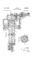
- FIGS. 13, inclusive a pneumatic sledge hammer constructed according to the principles of the present invention is shown in FIGS. 13, inclusive, and designated generally by the reference numeral 10. It is comprised of a first cylinder 11 having a closed end 12 and a removable plate 13 at the other end 14. Removable plate 13 is connected to the first cylinder by any convenient means such as threads 15. Elongated second cylinder 16, integrally formed with plate 13, is disposed coaxially with first cylinder 11 and has an inner end portion 17 lying within said first cylinder. First piston 18 is operable in said first cylinder and is slidably mounted on inner end portion 17 for axial movement thereon. 0 rings 19, 21 of neoprene, etc.
- Piston 18 has sleeve extension 23 on its inner end 24 which has a plurality of peripherally spaced longitudinal slots or apertures 25 extending therethrough to provide fluid passages as will be explained hereafter.
- Coil spring 26 is disposed in the reduced cylindrical end portion 27 of the first cylinder 11 and extends axially along the cylinder into engagement with inner face 28 of first piston 18 and biases said piston into a normal position against the removable plate 13 as shown.
- Circular disc or cap 29, having a peripheral lip 30 fits against the enlarged inner end 31 on the second cylinder 17.
- Gasket means 32 of neoprene or the like is affixed to the lip 39 to enhance the closure of lip 30 against inner end 31 thereby developing a fluid tight seal between cylinders 11 and 17.
- Coil spring 33 of considerably smaller diameter than spring 26, is disposed in central recessed portion 34 at closed end 12, coaxial with spring 26 and contacts recessed portion 25 on cap 29 to bias the latter member against end 31 of cylinder 16.
- hammer means 36 which comprises striker head 37, elongated guide arm or rod 38 extending rearwardly from head 37 (or to the right as shown in FIG. 2) and hammer piston 39 operable in said second cylinder 16 and slideably disposed on said arm 38 for movement between limiting positions defined by striker head 37 at one end and end fastening means 40 consisting of a nut or the like threaded onto the inner end 41 of said arm 38.
- Coil spring 42 is disposed in cylinder 16 and biases hammer assembly 36 to the normal position shown in FIG. 2 in which hammer piston 39 bears against the radially inwardly extending enlarged inner end 31 of cylinder 16 and is at the second limiting position, i.e., against fastening means 40, on guide arm 38, thereby being remote from striker head 3-7.
- inserter pin 46 Screwed into the outer face 43 of striker head 37 is threaded plug 44 which carries one end 45 of inserter pin 46 and thereby mounts the latter centrally aligned with hammer means 36.
- the other end 47 of inserter pin 46 is slideable through slot 48 in striker plate 49 mounted on the inner face 50 of plug 51 threadably engaging the outer end portion 52 of cylinder 16 (see also FIGS. 7 and 8).
- End 47 of striker pin 46 is enlarged as shown in FIG. 7 so that it cannot pass through slot 48, or to the right as viewed in FIG. 7, to insure proper alignment of pin '46 at all times.
- Fastener feeding means 53 is disposed at the outer end 52 of cylinder 16.
- Base member 54 extends from n threaded insert or plug 51 and has elongated rectangular operating slot 55 in its upper face 56 axially aligned with inserter pin 46 and dimensioned to receive fastener 57 for use.
- Base member 54 has curved bottom 58 and elongated fastener magazine 59 alhxed on its upper surface 56 in a perpendicular relation as shown and in communication with operating slot 55. on the top of a stack of staples 61.
- Roller 62 is rotatably mounted on lateral bracket 63 on magazine 59 adjacent base member 54.
- the roller 62 is aligned with the curved bottom surface 58 and constant force leaf spring 64 is afiixed at one end 65 to the periphery 66 of roller 62 and is trained around curved surface 58 and extends upwardly as viewed in FIG. 6 along the magazine and is connected with follower 68 at its upper end 67.
- Spring 64 is slideable around curved surface 58 and onto roller 62 as follower 60 moves toward slot 55 in base member 54 and provides constant feeding force on fasteners 61.
- Control valve means 71 comprises a line valve 72 which is actuated by trigger 73 to supply air from entry channel 74 to the inner chamber 75 of cylinder 11.
- Line valve 72 is comprised of the parts shown in FIG. 5.
- Slotted sleeve 76 is inserted into cylindrical bore 77 in the handle 68 and retained therein by press fit or other suitable means with peripheral slot 78 aligned with air passage 79 and peripheral slot 88 aligned with handle exhaust passage 81.
- the sleeve 76 is dimensioned so that its inner end 82 terminates short of air supply passage 74.
- Plunger 83 is axially slideable in bore 77 and has an arm 84 extending axially thereof and is connected to button 85 which is slideable in slotted sleeve 76.
- Gasket 86 is provided on the plunger for sealing engagement with the inner end 82 of the slotted sleeve 76. Coil.
- Spring 87 bears against the plunger 83 and biases it into sealing engagement with the inner end 82 of the slotted sleeve 76 or to the left as viewed in FIGS. 2 and 3.
- Threaded plug 88 threadably engages the plunger end 89 of cylindrical bore 77 and provides manual adjustment of spring bias on the plunger 83.
- Bleed valve 98 is interconnected between passages 79 and the interior of cylinder 11 on the closed end side 91 thereof (see also FIG. 4).
- Bleed valve is comprised of slideable sleeve '92 having an annular groove 93 near its inner closed end 94 and another annular groove 95 near its outer open end 96.
- Sleeve 92 is axially slideable in bore 97 in cylindrical head 98.
- Coil spring 99 extends into axial recess 188 in sleeve 92 and bears against adjustment screw 101 which threadably engages bushing 162 threaded into the outer end of recess 97, to provide normal bias of sleeve 92 all the way to the left as shown in FIG. 2.
- an automatic oiling mechanism 187 (see FIG. 1) which drips oil into annular groove 95 when it is to the right of ports 164, as viewed in FIG. 2 so that upon each movement of the bleed valve to its open position, i.e., with annular groove 95 aligned with ports 164, 185, oil will be sprayed into cylindrical chamber 91 and lubricate all of the moving parts.
- Threaded plug 188 is provided adjacent operating handle 68 and communicating with air passage 79 to provide access for cleaning purposes, etc.
- the hammer In use, the hammer is held by its operating handle 68 and the outer end 109 of operating slot .35 is placed against the work piece at the point where it is desired to drive the fastener 57 next to be driven by the hammer. With the mechanism as shown in FIG. 2 trigger 73 is pressed to the right thereby closing off exhaust passage 81 interconnecting supply passage 74 with passage 79 and delivering compressed air into the larger cylinder 11. Depending on the preselected tension of spring 99 air is bled through bleed valve 90 into chamber 91 as well as delivered to the underside of piston 18. When suitable pressure has been developed in chamber 91, it is distributed to the closed end 94- of sleeve 92 through passage 186 and closes bleed valve 90.
- the volume in chamber 91 displaced by movement of piston 18 toward closed end 12 is substantially equal to the increase of volume in cylinder 16 caused by movement of hammer piston 39 away from the inner end 31 thereof. This design thereby provides a constant pressure in the device during the entire working stroke.
- any suitable materials may be used for the parts of the hammer.
- Tool steel has been found suitable for the striker plate 49 and inserter pin 46.
- Cold rolled steel has proven satisfactory for the operating slot 55.
- the pistons 18 and 39 may be made of cast iron in order to avoid scoring of the cylinders 11 and 16 which can be made of steel.
- the first cylinder 11 can also be an aluminum casting and the valve parts may be of brass. Normally it has been found that the various coil springs can be of a strength from about eighty to one hundred pounds, but this value can vary depending upon choice.
- a driving means comprising a first cylinder, a second cylinder of smaller diameter than said first cylinder having an inner end portion lying within said first cylinder, a first piston operable in said first cylinder and slideably mounted on said end portion, spring means biasing said first piston against said other end, first valve means closing said inner end, said first piston movable against said first valve means to open said inner end, control valve means on said first cylinder to' introduce fluid under pressure into said first cylinder to operate said first piston, hammer means in said second cylinder including a striker head, an elongated guide arm on said head, a hammer piston operable in said second cylinder and slideable on said arm, means on said striker head engageable with said fastener to transmit driving force from said hammer means to said fastener, said hammer piston, upon opening of said first valve means in response to actuation by said first piston, being mov
- a driving means comprising a first cylinder, an elongated second cylinder of smaller diameter than said first cylinder disposed coaxially therewith and having an inner end portion lying within said first cyilnder, a first piston operable in said first cylinder and slideably mounted on said end portion, spring means biasing said first piston against said other end, spring biased first valve means closing said inner end, said first piston movable against said first valve means to open said inner end, control valve means on said first cylinder to introduce fluid under pressure into said first cylinder to operate said first piston, hammer means in said second cylinder including a striker head, an elongated guide arm on said head, a hammer piston operable in said second cylinder and slideable on said arm, spring means in contact with said hammer piston for biasing said hammer means to a neutral position against said inner end of said second cylinder and at the end of said guide arm
- a driving means comprising a first cylinder having a closed end and a removable plate on the other end, an elongated second cylinder of smaller diameter than said first cylinder disposed coaxially therewith and having an inner end portion lying within said first cylinder, a first piston operable in said first cylinder and slideably mounted on said end portion, spring means disposed at said closed end biasing said first piston back along said second cylinder against said other end, spring biased first valve means closing said inner end, said first piston having a sleeve extension on one end movable against said first valve means to open said inner end, said extension having a plurality of longitudinal slots in its periphery to provide fluid communication between said cylinders when said first valve means is opened, control valve means on said first cylinder to introduce fluid under pressure into said first cylinder to operate said first piston, hammer means in said second cylinder including a striker head, an elongated second cylinder of smaller diameter than said first cylinder disposed coaxially therewith and having an inner end portion lying within said first cylinder,
- a driving means comprising a first cylinder having a closed end and a removable plate on the other end, an elongated second cylinder of smaller diameter than said first cylinder disposed coaxially therewith and having an inner end portion lying within said first cylinder, at first piston operable in said first cylinder and slideably mounted on said end portion, spring means biasing said first piston back along said second cylinder against said other end, a removable cap on the inner end of said second cylinder, spring means biasing said cap against said inner end in fluid tight relation, first valve means closing said inner end, said first piston having a sleeve extension on one end movable against said cap, first valve means to open said inner end, said extension having a plurality of longitudinal slots in its periphery to provide fluid communication between said cylinders when said cap is removed, control valve means on said first cylinder to introduce fluid under pressure into said first cylinder to operate said first piston,
- a driving means comprising a first cylinder having a closed end and a removable plate on the other end, an elongated second cylinder of smaller diameter than said first cylinder disposed coaxially therewith and having an inner end portion lying With-in said first cylinder, a first piston operable in said first cylinder and slideably mounted on said end portion, spring means disposed at said closed end biasing said first piston back along said second cylinder against said other end, a removable cap on the inner end of said second cylinder, spring means biasing said cap against said inner end in fluid tight relation, said first piston having a sleeve extension on one end movable against said cap to open said inner end, said extension having a plurality oi spaced longitudinal slots in its periphery to provide fluid comninication between said cylinder when said cap is removed, control valve means on said first cylinder to introduce fluid under pressure into said first cylinder to operate
- a driving means comprising a first cylinder having a closed end and a removable plate on the other end, an elongated second cylinder integrally formed with said plate of smaller diameter than said first cylinder disposed coaxially therewith and having an inner end portion lying within said first cylinder, a first piston operable in said first cylinder and slideably mounted on said end portion, spring means disposed at said closed end biasing said first piston back along said second cylinder against said other end, a removable cap on the inner end of said second cylinder, spring means biasing said cap against said inner end in fluid tight relation, said first piston having a sleeve extension on one end movable against said cap to open said inner end, said extension having four spaced longitudinal slots in its periphery to provide fluid communication between said cylinder when said cap is removed, control valve means on said first cylinder to introduce iluid under pressure into said first cylinder to operate said first piston
- a driving mechanism comprising a first cylinder, a second cylinder of smaller diameter than said first cylind'er having an inner end portion lying within said first cylinder, a first piston operable in said first cylinder and longitudinally slideable on said end portion, spring means biasing said first piston back along said second cylinder against said other end, first valve means closing said inner end, said first piston movable against said first valve means to open said inner end, control valve means on said first cylinder to introduce fluid under pressure into said first cylinder to operate said first piston, said control valve means comprising a line valve for controlling fiow of fluid to the bottom of face of said first piston from a supply and a normally open bleed valve interposed between said line 'valve and said first piston communicating with said first cylinder, said bleed valve closeable after a preselected pressure is developed in said first cylinder upon opening of said line valve, said valve spring biased to a normally off
- a driving mechanism comprising a first cylinder, an elongated second cylinder of smaller diameter than said first cylinder disposed coaxially therewith and having an inner end portion lying within said first cylinder, a first piston operable in said first cylinder and longitudinally slideable on said end portion, spring means biasing said first piston against said other end, spring biased first valve means closing said inner end, said first piston movable against said first valve means to open said inner end, control valve means on said first cylinder to introduce fluid under pressure into said first cylinder to operate said first piston, said control valve means comprising a line valve for controlling flow of fluid to the bottom face of said first piston from a supply and a normally open bleed valve interposed between said line valve and said first piston communicating with said first cylinder, said bleed valve closeable after a preselected pressure is developed in said first cylinder upon opening of said line valve, said line valve spring biased to a normally off position
- a driving mechanism comprising a first cylinder having a closed end and a removable plate on the other end, an elongated second cylinder of smaller diameter than said first cylinder disposed coaxially therewith and having an inner end portion lying within said first cylinder, a first piston operable in said first cylinder and longitudinally slideable on said end portion, spring means disposed at said closed end biasing said first piston back along said second cylinder against said other end, spring biased first valve means closing said inner end, said first piston having a sleeve extension on one end movable against said first valve means to open said inner end, said extension having a plurality of longitudinal slots in its periphery to provide fluid communication between said cylinders when said first valve means is opened, control valve means on said first cylinder to introduce fluid under pressure into said first cylinder to operate said first piston, said control valve means comprising a line valve for controlling flow of fluid to the bottom face
- hammer piston operable in said second cylinder and slideable on said arm, spring means in contact with said hammer piston for biasing said hammer means to a neutral position against said inner end of said second cylinder and at the end of said guide arm remote from said striker head, means on said striker head engageable with said fastener to transmit driving force from said hammer means to said fastener, said hammer piston, upon opening of said first valve means in response to actuation by said first piston, being movable along said guide arm and against said striker head, said hammer means then movable in a continuing stroke as a unit along said second cylinder against the spring bias to impart driving force to said fastener.
- a driving mechanism comprising a first cylinder having a closed end and a removable plate on the other end, an elongated second cylinder of smaller diameter than said first cylinder disposed coaxially therewith and having an inner end portion lying within said first cylinder, a first piston operable in said first cylinder and longitudinally slideable on said end portion, spring means disposed at said closed end biasing said first piston back along said second cylinder against said other end, a re movable cap in the inner end of said second cylinder, spring means biasing said cap against said inner end in fluid tight relation, said first piston having a sleeve extension on one end movable against said cap to open said inner end, said extension having a plurality of longitudinal slots in its periphery to provide fluid commuication between said cylinders when said cap is removed, control valve means on said first cylinder to introduce air under pressure into said first cylinder to
- a driving mechanism comprising a first cylinder having a closed end and a removable plate on the other end, an elongated second cylinder of smaller diameter and total volume than said first cylinder disposed coaxially therewith and having an inner end portion lying within said first cylinder, a first piston operable in said first cylinder and longitudinally slideable on said end portion, spring means disposed at said closed end biasing.
- said first piston back along said second cylinder against said other end, a removable cap on the inner end of said second cylinder, spring means biasing said cap against said 1 1 inner end in fluid tight relation, said first piston having a sleeve extension on one end movable against said cap to open said inner end, said extension having a plurality of spaced longitudinal slots in its periphery to provide fluid communication between said cylinders when said cap is removed, control valve means on said first cylinder to introduce air under pressure into said first cylinder to operate said first piston, said control valve means comprising a line valve for controlling flow of air to the bottom face of said first piston from a supply and a normally open bleed valve interposed between said line valve and said first piston communicating with said first cylinder, said bleed valve closeable after a preselected pressure is developed in said first cylinder upon opening of said line valve, said line valve spring biased to a normally off position at which said first cylinder is exhausted from the bottom face of said first piston, hammer means in said second cylinder including a striker head, an
- a driving mechanism comprising a first cylinder having a closed end and a removable plate on the other end, an elongated second cylinder integrally formed with said plate of smaller diameter and total volume than said first cylinder disposed coaxially therewith and having an inner end portion lying within said first cylinder, a first piston operable in said first cylinder and longitudinally slideable on said end portion, spring means disposed at said closed end biasing said first piston back along said second cylinder against said other end, a removable cap on the inner end of said second cylinder, spring means biasing said cap against said inner end in fluid tight relation, said first piston having a sleeve extension on one end movable against said cap to open said inner end, said extension having four spaced longitudinal slots in its periphery to provide fluid communication between said cylinders when said cap is removed, control valve means on said first cylinder to introduce air under pressure) into said first cylinder to operate
Description
8, 1961 A. ST'ElNER 2,995,113
PNEUMATIC SLEDGE HAMMER Filed March 25, 1960 3 Sheets-Sheet 1 55 so" 56 I .1. E INVENTOR. I
a ALO/S STEl/YEQ 58 BY Aug. 8, 1961 A. STEINER PNEUMATIC SLEDGE HAMMER 3 Sheets-Sheet 2 Filed March 23, 1960 INVENTOR. ALo/s Sreuvag Aug. 8, 1961 A. STEINER PNEUMATIC SLEDGE HAMMER 3 Sheets-Sheet Filed March 23, 1960 INVENTOR. ALo/s STE N6 #Lbdv WM il'nited rates Patent Q 2,995,113 PNEUMATIC SLEDGE HAMMER Aiois Steiner, 410 16th St., Union City, NJ. Filed Mar. 23, 1960, Ser. No. 17,007 12 Claims. or. 121-13 This invention relates to a device for driving large fasteners completely home in one stroke into any kind of wood and is particularly useful in laying hardwood floormg.
An object of this invention is to provide a pneumatically operated hammer mechanism which can be adjusted from a gentle tap to a substantial impact of the hammer means on the fastener being driven into a work piece.
Another object is to provide a pneumatic hammer mechanism in which the hammer means has a constant pressure on it throughout its working stroke.
An additional object is to provide such a device which is easily lubricated through the driving cylinder automatically during use.
A further object is to provide a fastener feed magazine having a constant force spring, by which means the fasteners are fed to the operating slot in the hammer under a constant force.
Briefly, the present invention relates to a portable pneumatic sledge hammer comprising a first cylinder having a closed end and a removable plate on the other end and an elongated second cylinder integrally formed with said plate, of smaller diameter than said first cylinder, and disposed coaxially therewith and having an inner end portion lying within said first cylinder. A first piston is operable in said first cylinder and is slideably mounted on said end portion. Spring means is disposed at the closed end of said first cylinder and biases the first piston back along the second cylinder against said other end. The inner end of the second cylinder has a removable cap which is spring biased against said inner end in fluid tight relation and the first piston has a sleeve extension on one end which is movable against the cap to open said inner end. Said extension has four peripherally spaced longitudinal slots to provide fluid communication between the cylinders when the cap is removed.
Control valve means is provided on the first cylinder to introduce fluid under pressure into the first cylinder to operate said first piston. Hammer means is disposed in the second cylinder and includes a striker head and an elongated guide arm on the head, a hammer piston operable in the second cylinder and slideable on said arm, and spring means in contact with said hammer piston for biasing said hammer means to a neutral position against the inner end of the second cylinder and at the end of the guide arm remote from the striker head.
Fastener feeding means is attached at the outer end of the second cylinder and pin means is provided on the striker head which is engageable with the feeder means to transmit driving force from the hammer means to a fastener delivered by the feeder means. The hammer piston, upon removal of said cap in response to actuation by the first piston, is movable along the guide arm and against the striker head, the entire hammer means then movable in a continuing stroke as a unit along the second cylinder against the spring bias to impart driving force to the fastener.
The two cylinders and the first piston are dimensioned so that the decrease in volume at the closed end of the first cylinder during actuation is substantially equal to the increase in volume at the inner end of the second cylinder, so that substantially constant operating pressure is maintained on the hammer means throughout the working stroke of the device.
The fastener feeding means comprises a base member having an elongated operating slot in one face thereof ICC dimensioned to receive a fastener for use. An elongated fastener magazine is aflixed to said base member perpendicular to said face and communicating with said slot. Follower means is disposed in said magazine and constant force spring means on said magazine is intercon nected with said follower means to urge a stack of staples in said magazine toward the operating slot for use. The spring means includes a roller laterally disposed on the magazine adjacent the base member and aligned with the curved bottom surface of the latter. The constant force leaf spring is affixed at one end to the periphery of the roller and is disposed around the curved bottom surface of the base member with its upper end operably connected to the follower means. The spring is slideable around said curved bottom surface and onto said roller as said follower means moves in the magazine toward the operating slot.
Other objects and features of the invention will become apparent in the following description and claims, and in the drawings in which:
FIG. 1 is a perspective view of one form of the device;
FIG. 2 is an enlarged side elevational View in section showing the operating mechanism in the normal at rest position;
FIG. 3 is a view similar'to that of FIG. 2 showing the operating mechanism in the fully actuated position;
FIG. 4 is an exploded view of the parts of the bleed valve;
FIG. 5 is an exploded view of the parts of the line valve;
FIG. 6 is a section taken along lines 6-6 of FIG. 1;
FIG. 7 is an enlarged plan view of the device shown in FIG. 6;
FIG. 8 is a section taken along lines 8-8 of FIG. 7; and
FIG. 9 is a section taken along lines 99 of FIG. 2.
Referring now to the drawings, a pneumatic sledge hammer constructed according to the principles of the present invention is shown in FIGS. 13, inclusive, and designated generally by the reference numeral 10. It is comprised of a first cylinder 11 having a closed end 12 and a removable plate 13 at the other end 14. Removable plate 13 is connected to the first cylinder by any convenient means such as threads 15. Elongated second cylinder 16, integrally formed with plate 13, is disposed coaxially with first cylinder 11 and has an inner end portion 17 lying within said first cylinder. First piston 18 is operable in said first cylinder and is slidably mounted on inner end portion 17 for axial movement thereon. 0 rings 19, 21 of neoprene, etc. provide fluid tight seals at the inner periphery 21 and outer periphery 22 respectively of piston 18. Piston 18 has sleeve extension 23 on its inner end 24 which has a plurality of peripherally spaced longitudinal slots or apertures 25 extending therethrough to provide fluid passages as will be explained hereafter. Coil spring 26 is disposed in the reduced cylindrical end portion 27 of the first cylinder 11 and extends axially along the cylinder into engagement with inner face 28 of first piston 18 and biases said piston into a normal position against the removable plate 13 as shown.
Circular disc or cap 29, having a peripheral lip 30 fits against the enlarged inner end 31 on the second cylinder 17. Gasket means 32 of neoprene or the like is affixed to the lip 39 to enhance the closure of lip 30 against inner end 31 thereby developing a fluid tight seal between cylinders 11 and 17. Coil spring 33, of considerably smaller diameter than spring 26, is disposed in central recessed portion 34 at closed end 12, coaxial with spring 26 and contacts recessed portion 25 on cap 29 to bias the latter member against end 31 of cylinder 16.
Slideably disposed in cylinder 16 for axial movement therein is hammer means 36 which comprises striker head 37, elongated guide arm or rod 38 extending rearwardly from head 37 (or to the right as shown in FIG. 2) and hammer piston 39 operable in said second cylinder 16 and slideably disposed on said arm 38 for movement between limiting positions defined by striker head 37 at one end and end fastening means 40 consisting of a nut or the like threaded onto the inner end 41 of said arm 38.
Screwed into the outer face 43 of striker head 37 is threaded plug 44 which carries one end 45 of inserter pin 46 and thereby mounts the latter centrally aligned with hammer means 36. The other end 47 of inserter pin 46 is slideable through slot 48 in striker plate 49 mounted on the inner face 50 of plug 51 threadably engaging the outer end portion 52 of cylinder 16 (see also FIGS. 7 and 8). End 47 of striker pin 46 is enlarged as shown in FIG. 7 so that it cannot pass through slot 48, or to the right as viewed in FIG. 7, to insure proper alignment of pin '46 at all times.
Fastener feeding means 53 is disposed at the outer end 52 of cylinder 16. Base member 54 extends from n threaded insert or plug 51 and has elongated rectangular operating slot 55 in its upper face 56 axially aligned with inserter pin 46 and dimensioned to receive fastener 57 for use. Base member 54 has curved bottom 58 and elongated fastener magazine 59 alhxed on its upper surface 56 in a perpendicular relation as shown and in communication with operating slot 55. on the top of a stack of staples 61.
Operating fluid, i.e. compressed air, is fed to the hammer through operating handle '68. Suitable hose connection means 69 is prow'ded at the outer end 70 of handle 68 to supply air to the control valve means 71. Control valve means 71 comprises a line valve 72 which is actuated by trigger 73 to supply air from entry channel 74 to the inner chamber 75 of cylinder 11. Line valve 72 is comprised of the parts shown in FIG. 5. Slotted sleeve 76 is inserted into cylindrical bore 77 in the handle 68 and retained therein by press fit or other suitable means with peripheral slot 78 aligned with air passage 79 and peripheral slot 88 aligned with handle exhaust passage 81. The sleeve 76 is dimensioned so that its inner end 82 terminates short of air supply passage 74. Plunger 83 is axially slideable in bore 77 and has an arm 84 extending axially thereof and is connected to button 85 which is slideable in slotted sleeve 76. Gasket 86 is provided on the plunger for sealing engagement with the inner end 82 of the slotted sleeve 76. Coil.
Bleed valve 98 is interconnected between passages 79 and the interior of cylinder 11 on the closed end side 91 thereof (see also FIG. 4). Bleed valve is comprised of slideable sleeve '92 having an annular groove 93 near its inner closed end 94 and another annular groove 95 near its outer open end 96. Sleeve 92 is axially slideable in bore 97 in cylindrical head 98. Coil spring 99 extends into axial recess 188 in sleeve 92 and bears against adjustment screw 101 which threadably engages bushing 162 threaded into the outer end of recess 97, to provide normal bias of sleeve 92 all the way to the left as shown in FIG. 2. An 0 ring 183 of neoprene or the like is inserted in annular groove 93 to provide fluid tight seal of sleeve 92 in cylindrical bore 97. Sleeve 92 is normally maintained in the position shown in PEG. 2 wherein passage 79 is interconnected with cylindrical chamber 91 through the alignment of annular recess 95 with ports 184, 185 in the cylindrical head 98. When suflicient pressure is developed in chamber 91 by such interconnection with passage 79 then such pressure, through passage 186, pushes against the closed end 94 of sleeve 92 and overcomes the spring bias, pushing the sleeve to the right into the position shown in FIG. 3, moving annular recess 94 out of alignment with ports 104, 185, thereby disconnecting passage 79 from cylindrical chamber 91. Screw 181 may be manually adjusted to vary the bias of spring 99 and determine pressure required in chamber 91 to close off bleed valve 90.
In conjunction with bleed valve 98 is an automatic oiling mechanism 187 (see FIG. 1) which drips oil into annular groove 95 when it is to the right of ports 164, as viewed in FIG. 2 so that upon each movement of the bleed valve to its open position, i.e., with annular groove 95 aligned with ports 164, 185, oil will be sprayed into cylindrical chamber 91 and lubricate all of the moving parts. Threaded plug 188 is provided adjacent operating handle 68 and communicating with air passage 79 to provide access for cleaning purposes, etc.
In use, the hammer is held by its operating handle 68 and the outer end 109 of operating slot .35 is placed against the work piece at the point where it is desired to drive the fastener 57 next to be driven by the hammer. With the mechanism as shown in FIG. 2 trigger 73 is pressed to the right thereby closing off exhaust passage 81 interconnecting supply passage 74 with passage 79 and delivering compressed air into the larger cylinder 11. Depending on the preselected tension of spring 99 air is bled through bleed valve 90 into chamber 91 as well as delivered to the underside of piston 18. When suitable pressure has been developed in chamber 91, it is distributed to the closed end 94- of sleeve 92 through passage 186 and closes bleed valve 90. At this point no further compressed air is delivered to the closed end chamber 91, but is thereafter delivered entirely against the underside 1-10 of piston 18 to move the piston to the right as viewed in FIGS. 2 and 3 to the position shown in FIG. 3. In this travel sleeve extension 23 of piston 1-8 unseats cap 29 from sealing engagement with end 31 of cylinder 16. Slots 25 in sleeve 23 permit delivery of the compressed air from chamber 91 into cylinder 16 and against hammer piston 39. The movement of piston 18 in response to the compressed air delivered to its underside 110 is very quick and causes a quick opening of the cap 29 with a corresponding sudden movement of hammer piston 39 slideably along guide arm 38 and against striker head 37 with a sudden impact which results in hammer means 36 driving striker pin 46 against fastener 57 in operating groove 55 until the fully actuated position as shown in FIG. 3 is reached. At this point the fastener has been driven into the work piece (not shown). Exhaust ports 111 are provided near the outer end 52 of cylinder 16 to permit air in the outer end portion 112 of cylinder 16 to escape and avoid the buildup of back pressure which would tend to diminish the driving impact of the hammer means 36.
By adjustment of screw 101, the actuation of hammer means 36 can be varied from a gentle tap to a tremendous blow. By unscrewing the screw to the right as viewed in FIG. 2, the bias of spring 99 is decreased and the actuation of the hammer means 36 is thereby proportionately diminished. Correspondingly, adjustment of the spring inwardly or to the left as viewed in FIG. 2 produces actuation of greater force. The air bled into chamber 91 after closure of bleed valve 90 is compressed by piston 18 prior to opening of the cap 29 and adjustment of bleed valve 96 thus determines the preselected compression of the air in chamber 91 which is to be used to actuate the hammer means 39.
The volume in chamber 91 displaced by movement of piston 18 toward closed end 12 is substantially equal to the increase of volume in cylinder 16 caused by movement of hammer piston 39 away from the inner end 31 thereof. This design thereby provides a constant pressure in the device during the entire working stroke.
After the fastener 57 has been driven into the work piece as just described, release of trigger 73 will cause line valve 72 to shift back to its normal position in which supply passage 74- is closed off and exhaust passage 81 is interconnected, through slots 80 and 78 of sleeve 76 with passage 79. Spring 42 moves the hammer piston 39 back along the interior of cylinder 16 to the right (as viewed in FIG. 2) and springs 33 and 26 reset their respective parts, i.e., cap 29 and piston 18. The air pressure from chamber 75 is thereby exhausted through passage 79, line valve 72 and exhaust passage 81. All parts are returned to their positions as shown in FIG. 2.
Any suitable materials may be used for the parts of the hammer. Tool steel has been found suitable for the striker plate 49 and inserter pin 46. Cold rolled steel has proven satisfactory for the operating slot 55. The pistons 18 and 39 may be made of cast iron in order to avoid scoring of the cylinders 11 and 16 which can be made of steel. The first cylinder 11 can also be an aluminum casting and the valve parts may be of brass. Normally it has been found that the various coil springs can be of a strength from about eighty to one hundred pounds, but this value can vary depending upon choice.
While one embodiment of the invention has been shown and described it is to be understood that various changes and additions can be made by those skilled in the art without departing from the scope and spirit of the invention.
This application is a continuation-in-part of application Ser. No. 716,776, filed February 21, 1958.
What is claimed is:
1. In a portable pneumatic sledge hammer of the type used for driving a fastener into a work piece or the like, a driving means comprising a first cylinder, a second cylinder of smaller diameter than said first cylinder having an inner end portion lying within said first cylinder, a first piston operable in said first cylinder and slideably mounted on said end portion, spring means biasing said first piston against said other end, first valve means closing said inner end, said first piston movable against said first valve means to open said inner end, control valve means on said first cylinder to' introduce fluid under pressure into said first cylinder to operate said first piston, hammer means in said second cylinder including a striker head, an elongated guide arm on said head, a hammer piston operable in said second cylinder and slideable on said arm, means on said striker head engageable with said fastener to transmit driving force from said hammer means to said fastener, said hammer piston, upon opening of said first valve means in response to actuation by said first piston, being movable along said guide aunt and against said striker head, said hammer means then movable in a continuing stroke as a unit along said second cylinder against the spring bias to impart driving force to said fastener.
2. In a portable pneumatic sledge hammer of the type used for driving a fastener into a work piece or the like, a driving means comprising a first cylinder, an elongated second cylinder of smaller diameter than said first cylinder disposed coaxially therewith and having an inner end portion lying within said first cyilnder, a first piston operable in said first cylinder and slideably mounted on said end portion, spring means biasing said first piston against said other end, spring biased first valve means closing said inner end, said first piston movable against said first valve means to open said inner end, control valve means on said first cylinder to introduce fluid under pressure into said first cylinder to operate said first piston, hammer means in said second cylinder including a striker head, an elongated guide arm on said head, a hammer piston operable in said second cylinder and slideable on said arm, spring means in contact with said hammer piston for biasing said hammer means to a neutral position against said inner end of said second cylinder and at the end of said guide arm remote from said striker head, means on said striker head engageable with said fastener to transmit driving force from said hammer means to said fastener, said hammer piston, upon opening of said first valve means in response to actuation by said first piston, being movable along said guide arm and against said striker head, said hammer means then movable in a continuing stroke as a unit along said second cylinder against the spring bias to impart driving force to said fastener.
3. In a portable pneumatic sledge hammer of the type used for driving a fastener into a work piece or the like, a driving means comprising a first cylinder having a closed end and a removable plate on the other end, an elongated second cylinder of smaller diameter than said first cylinder disposed coaxially therewith and having an inner end portion lying within said first cylinder, a first piston operable in said first cylinder and slideably mounted on said end portion, spring means disposed at said closed end biasing said first piston back along said second cylinder against said other end, spring biased first valve means closing said inner end, said first piston having a sleeve extension on one end movable against said first valve means to open said inner end, said extension having a plurality of longitudinal slots in its periphery to provide fluid communication between said cylinders when said first valve means is opened, control valve means on said first cylinder to introduce fluid under pressure into said first cylinder to operate said first piston, hammer means in said second cylinder including a striker head, an elongated guide arm on said head, a hammer piston operable in said second cylinder and slideable on said arm, spring means in contact with said hammer piston for biasing said hammer means to a neutral position against said inner end of said second cylinder and at the end of said guide arm remote from said striker head, means on said striker head engageable with said fastener to transmit driving force from said hammer means to said fastener, said hammer piston, upon opening of said first valve means in response to actuation by said first piston, being movable along said guide arm and against said striker head, said hammer means then movable in a continuing stroke as a unit along said second cylinder against the spring bias to impart driving force to said fastener.
4. In a portable pneumatic sledge hammer of the type used for driving a fastener into a work piece or the like, a driving means comprising a first cylinder having a closed end and a removable plate on the other end, an elongated second cylinder of smaller diameter than said first cylinder disposed coaxially therewith and having an inner end portion lying within said first cylinder, at first piston operable in said first cylinder and slideably mounted on said end portion, spring means biasing said first piston back along said second cylinder against said other end, a removable cap on the inner end of said second cylinder, spring means biasing said cap against said inner end in fluid tight relation, first valve means closing said inner end, said first piston having a sleeve extension on one end movable against said cap, first valve means to open said inner end, said extension having a plurality of longitudinal slots in its periphery to provide fluid communication between said cylinders when said cap is removed, control valve means on said first cylinder to introduce fluid under pressure into said first cylinder to operate said first piston, hammer means in said second cylinder including a striker head, an elongated guide arm on said head, a hammer piston operable in said second cylinder and slideable on said arm, spring means in contact with said hammer piston for biasing said hammer means to a neutral position against said inner end of said second cylinder and at the end of said guide arm remote from said striker head, means on said striker head engageable with said fastener to transmit driving force from said hammer means to said fastener, said hammer piston, upon removal of said cap in response to actuation by said first piston, being movable along said guide arm and against said striker head, said hammer means then movable in a continuing stroke as a unit along said second cylinder against the spring bias to impart driving force to said fastener.
5. in a portable pneumatic sledge hammer of the type used for driving a fastener into a work piece or the like, a driving means comprising a first cylinder having a closed end and a removable plate on the other end, an elongated second cylinder of smaller diameter than said first cylinder disposed coaxially therewith and having an inner end portion lying With-in said first cylinder, a first piston operable in said first cylinder and slideably mounted on said end portion, spring means disposed at said closed end biasing said first piston back along said second cylinder against said other end, a removable cap on the inner end of said second cylinder, spring means biasing said cap against said inner end in fluid tight relation, said first piston having a sleeve extension on one end movable against said cap to open said inner end, said extension having a plurality oi spaced longitudinal slots in its periphery to provide fluid comninication between said cylinder when said cap is removed, control valve means on said first cylinder to introduce fluid under pressure into said first cylinder to operate said first piston, hammer means in said second cylinder including a striker head, an elongated guide arm on said head, a hammer piston operable in said second cylinder and slideable on said arm, spring means in contact With said hammer piston for biasing said hammer means to a neutral position against said inner end of said second cylinder and at the end of said guide arm remote from said striker head, means on said striker head engageable with said iiastener to transmit driving force from said hammer means to said fastener, said hammer piston, upon removal of said cap in response to actuation by said first piston, being movable along said guide arm and against said striker head, said hammer means then movable in a continuing stroke as a unit along said second cylinder against the spring bias to impart driving force to said fastener, said cylinders and said first piston being dimensioned so that the decrease in volume at the closed end of said first cylinder during actuation is substantially equal to the increase in volume at the inner end of said second cylinder, whereby substantially constant operating pressure is maintained on said hammer means throughout the working stroke.
6. in a portable pneumatic sledge hammer of the type used for driving a fastener into a work piece or the like, a driving means comprising a first cylinder having a closed end and a removable plate on the other end, an elongated second cylinder integrally formed with said plate of smaller diameter than said first cylinder disposed coaxially therewith and having an inner end portion lying within said first cylinder, a first piston operable in said first cylinder and slideably mounted on said end portion, spring means disposed at said closed end biasing said first piston back along said second cylinder against said other end, a removable cap on the inner end of said second cylinder, spring means biasing said cap against said inner end in fluid tight relation, said first piston having a sleeve extension on one end movable against said cap to open said inner end, said extension having four spaced longitudinal slots in its periphery to provide fluid communication between said cylinder when said cap is removed, control valve means on said first cylinder to introduce iluid under pressure into said first cylinder to operate said first piston, hammer means in said second cylinder including a striker head, an elongated guide arm on said head, a hammer piston operable in said second cylinder and slideable on said arm, spring means in contact with said hammer piston for biasing said hammer means to a neutral position against said inner end of said second cylinder and at the end of said guide arm remote firom said striker head, pin means on said striker head engageable with said fastener to transmit driving force from said hammer means to said fastener, said hammer piston, upon removal of said cap in response to actuation by said first piston, being movable along said guide arm and against said striker head, said hammer means then movable in a continuing stroke as a unit along said second cylinder against the spring bias to impart driving force to said fastener, said cylinders and said first piston being dimensioned so that the decrease in volume at the closed end of said first cylinder during actuation is substantially equal to the increase in volume at the inner end of said second cylinder, whereby substantially constant operating pressure is maintained on said hammer means throughout the working stroke.
7. In a portable pneumatic sledge hammer of the type used for driving a fastener into a work piece or the like, a driving mechanism comprising a first cylinder, a second cylinder of smaller diameter than said first cylind'er having an inner end portion lying within said first cylinder, a first piston operable in said first cylinder and longitudinally slideable on said end portion, spring means biasing said first piston back along said second cylinder against said other end, first valve means closing said inner end, said first piston movable against said first valve means to open said inner end, control valve means on said first cylinder to introduce fluid under pressure into said first cylinder to operate said first piston, said control valve means comprising a line valve for controlling fiow of fluid to the bottom of face of said first piston from a supply and a normally open bleed valve interposed between said line 'valve and said first piston communicating with said first cylinder, said bleed valve closeable after a preselected pressure is developed in said first cylinder upon opening of said line valve, said valve spring biased to a normally off position at which said first cylinder is exhausted from the bottom face of said first piston, hammer means in said second cylinder including a striker head, an elongated guide arm on said head, a hammer piston operable in said second cylinder and slideable on said arm, means on said striker head engageable with said fastener to transmit driving force from said hammer means to said fastener, said hammer piston, upon opening of said first valve means in response to actuation by said first piston, being movable along said guide arm and against said striker head, said hammer means then movable in a continuing stroke as a unit along said second cylinder against the spring bias to impart driving :force to said fastener.
8. In a portable pneumatic sledge hammer of the type used for driving a fastener into a work piece or the like, a driving mechanism comprising a first cylinder, an elongated second cylinder of smaller diameter than said first cylinder disposed coaxially therewith and having an inner end portion lying within said first cylinder, a first piston operable in said first cylinder and longitudinally slideable on said end portion, spring means biasing said first piston against said other end, spring biased first valve means closing said inner end, said first piston movable against said first valve means to open said inner end, control valve means on said first cylinder to introduce fluid under pressure into said first cylinder to operate said first piston, said control valve means comprising a line valve for controlling flow of fluid to the bottom face of said first piston from a supply and a normally open bleed valve interposed between said line valve and said first piston communicating with said first cylinder, said bleed valve closeable after a preselected pressure is developed in said first cylinder upon opening of said line valve, said line valve spring biased to a normally off position at which said first cylinder is exhausted from the bottom face of said first piston, hammer means in said second cylinder including a striker head, an elongated guide arm on said head, a hammer piston operable in said second cylinder and slideable on said arm, spring means in contact with said hammer piston for biasing said hammer means to a neutral position against said inner end of said second cylinder and at the end of said guide arm remote from said striker head, means on said striker head engageable with said fastener to transmit driving force from said hammer means to said fastener, said hammer piston, upon opening of said first valve means in response to actuation by said first piston, being movable along said guide arm and against said striker head, said hammer means then movable in a continuing stroke as a unit along said second cylinder against the spring bias to impart driving force to said fastener.
9. In a portable pneumatic sledge hammer of the type used for driving a fastener into a work piece or the like, a driving mechanism comprising a first cylinder having a closed end and a removable plate on the other end, an elongated second cylinder of smaller diameter than said first cylinder disposed coaxially therewith and having an inner end portion lying within said first cylinder, a first piston operable in said first cylinder and longitudinally slideable on said end portion, spring means disposed at said closed end biasing said first piston back along said second cylinder against said other end, spring biased first valve means closing said inner end, said first piston having a sleeve extension on one end movable against said first valve means to open said inner end, said extension having a plurality of longitudinal slots in its periphery to provide fluid communication between said cylinders when said first valve means is opened, control valve means on said first cylinder to introduce fluid under pressure into said first cylinder to operate said first piston, said control valve means comprising a line valve for controlling flow of fluid to the bottom face of said first piston from a supply and a normally open bleed valve interposed between said line valve and said first piston communicating with said first cylinder, said bleed valve closeable after a preselected pressure is developed in said first cylinder upon opening of said line valve, said line valve spring biased to a normally off position at which said first cylinder is exhausted from the bottom face of said first piston, ham mer means in said second cylinder including a striker head, an elongated guide arm on said head, a. hammer piston operable in said second cylinder and slideable on said arm, spring means in contact with said hammer piston for biasing said hammer means to a neutral position against said inner end of said second cylinder and at the end of said guide arm remote from said striker head, means on said striker head engageable with said fastener to transmit driving force from said hammer means to said fastener, said hammer piston, upon opening of said first valve means in response to actuation by said first piston, being movable along said guide arm and against said striker head, said hammer means then movable in a continuing stroke as a unit along said second cylinder against the spring bias to impart driving force to said fastener.
10. In a portable pneumatic sledge hammer of the type used for driving a fastener into a work piece or the like, a driving mechanism comprising a first cylinder having a closed end and a removable plate on the other end, an elongated second cylinder of smaller diameter than said first cylinder disposed coaxially therewith and having an inner end portion lying within said first cylinder, a first piston operable in said first cylinder and longitudinally slideable on said end portion, spring means disposed at said closed end biasing said first piston back along said second cylinder against said other end, a re movable cap in the inner end of said second cylinder, spring means biasing said cap against said inner end in fluid tight relation, said first piston having a sleeve extension on one end movable against said cap to open said inner end, said extension having a plurality of longitudinal slots in its periphery to provide fluid commuication between said cylinders when said cap is removed, control valve means on said first cylinder to introduce air under pressure into said first cylinder to operate said first piston, said control valve means comprising a line valve for controlling flow of air to the bottom face of said first piston from a supply and a normally open bleed valve interposed between said line valve and said first piston communicating with said first cylinder, said bleed valve closeable after a preselected pressure is developed in said first cylinder upon opening of said line valve, said line valve spring biased to a normally ofi position at which said first cylinder is exhausted from the bottom face of said first piston, hammer means in said second cylinder including a striker head, an elongated guide arm on said head, a hammer piston operable in said second cylinder and slideable on said arm, spring means in contact with said hammer piston for biasing said hammer means to a neutral position against said inner end of said second cylinder and at the end of said guide arm remote from said striker head, means on said striker head engageable with said fastener to transmit driving force from said hammer means to said fastener, said hammer piston, upon removal of said cap in response to actuation by said first piston, being movable along said guide arm and against said striker head, said hammer means then movable in a continuing stroke as a unit along said second cylinder against the spring bias to impart driving force to said fastener.
11. In a portable pneumatic sledge hammer of the type used for driving a fastener into a Work piece or the like, a driving mechanism comprising a first cylinder having a closed end and a removable plate on the other end, an elongated second cylinder of smaller diameter and total volume than said first cylinder disposed coaxially therewith and having an inner end portion lying within said first cylinder, a first piston operable in said first cylinder and longitudinally slideable on said end portion, spring means disposed at said closed end biasing. said first piston back along said second cylinder against said other end, a removable cap on the inner end of said second cylinder, spring means biasing said cap against said 1 1 inner end in fluid tight relation, said first piston having a sleeve extension on one end movable against said cap to open said inner end, said extension having a plurality of spaced longitudinal slots in its periphery to provide fluid communication between said cylinders when said cap is removed, control valve means on said first cylinder to introduce air under pressure into said first cylinder to operate said first piston, said control valve means comprising a line valve for controlling flow of air to the bottom face of said first piston from a supply and a normally open bleed valve interposed between said line valve and said first piston communicating with said first cylinder, said bleed valve closeable after a preselected pressure is developed in said first cylinder upon opening of said line valve, said line valve spring biased to a normally off position at which said first cylinder is exhausted from the bottom face of said first piston, hammer means in said second cylinder including a striker head, an elongated guide arm on said head, a hammer piston operable in said second cylinder and slideable on said arm, spring means in contact with said hammer piston for biasing said hammer means to a neutral position against said inner end of said second cylinder and at the end of said guide arm remote from said striker head, means on said striker head engageable with said fastener to transmit driving force from said hammer means to said fastener, said hammer piston, upon removal of said cap in response to actuation by said first piston, being movable along said guide arm and against said striker head, said hammer means then movable in a continuing stroke as a unit along said second cylinder against the spring bias to impart driving force to said fastener, said cylinders and said first piston being dimensioned so that the decrease in volume at the closed end of said first cylinder during actuation is substantially equal to the increase in volume at the inner end of said second cylinder, whereby substantially constant operating pressure is maintained on said hammer means throughout the working stroke.
12. In a portable pneumatic sledge hammer of the type used for driving a fastener into a work piece or the like, a driving mechanism comprising a first cylinder having a closed end and a removable plate on the other end, an elongated second cylinder integrally formed with said plate of smaller diameter and total volume than said first cylinder disposed coaxially therewith and having an inner end portion lying within said first cylinder, a first piston operable in said first cylinder and longitudinally slideable on said end portion, spring means disposed at said closed end biasing said first piston back along said second cylinder against said other end, a removable cap on the inner end of said second cylinder, spring means biasing said cap against said inner end in fluid tight relation, said first piston having a sleeve extension on one end movable against said cap to open said inner end, said extension having four spaced longitudinal slots in its periphery to provide fluid communication between said cylinders when said cap is removed, control valve means on said first cylinder to introduce air under pressure) into said first cylinder to operate said first piston, said control valve means comprising a line valve for controlling flow of air to the bottom face of said first piston from a supply and a normally open bleed valve interposed between said line valve and said first piston communicating with said first cylinder, said bleed valve closeable after a preselected pressure is developed in said first cylinder upon opening of said line valve, said line valve spring biased to a normally off position at which said first cylinder is exhausted from the bottom face of said first piston, hammer means in said second cylinder including a striker head, an elongated guide arm on said head, a hammer piston operable in said second cylinder and slideable on said arm, spring means in contact with said hammer piston for biasing said hammer means to a neutral position against said inner end of said second cylinder and at the end of said guide arm remote from said striker head, pin means on said striker head engageable with said fastener to transmit driving force from said hammer means to said fastener, said hammer piston, upon removal of said cap in response to actuation by said first piston, being movable along said guide arm and against said striker head, said hammer means then movable in a continuing stroke as a unit along said second cylinder against the spring bias to impart driving force to said fastener, said cylinders and said first piston being dimensioned so that the decrease in volume at the closed end of said first cylinder during actuation is substantially equal to the increase in volume at the inner end of said second cylinder, whereby substantially constant operating pressure is maintained on said hammer means throughout the working stroke.
References Cited in the file of this patent UNITED STATES PATENTS 2,344,944 Hurst Mar. 28, 1944 2,406,747 Davis Sept. 3, 1946 2,430,321 Anstett NOV. 4, 1947 2,677,933 Hopkinson May 11, 1954 2,714,207 Lindstrom Aug. 2, 1955 2,729,198 Faccou Jan. 3, 1956 2,734,192 True Feb. 14, 1956 2,801,415 Jenny Aug. 6, 1957 2,854,953 Osborne Oct. 7, 1958 2,872,901 Goldring et al. Feb. 10, 1959 2,944,522 Doyle July 12, 1960
Priority Applications (1)
| Application Number | Priority Date | Filing Date | Title |
|---|---|---|---|
| US17007A US2995113A (en) | 1960-03-23 | 1960-03-23 | Pneumatic sledge hammer |
Applications Claiming Priority (1)
| Application Number | Priority Date | Filing Date | Title |
|---|---|---|---|
| US17007A US2995113A (en) | 1960-03-23 | 1960-03-23 | Pneumatic sledge hammer |
Publications (1)
| Publication Number | Publication Date |
|---|---|
| US2995113A true US2995113A (en) | 1961-08-08 |
Family
ID=21780205
Family Applications (1)
| Application Number | Title | Priority Date | Filing Date |
|---|---|---|---|
| US17007A Expired - Lifetime US2995113A (en) | 1960-03-23 | 1960-03-23 | Pneumatic sledge hammer |
Country Status (1)
| Country | Link |
|---|---|
| US (1) | US2995113A (en) |
Cited By (10)
| Publication number | Priority date | Publication date | Assignee | Title |
|---|---|---|---|---|
| US3147670A (en) * | 1961-05-10 | 1964-09-08 | Herman J Spencer | Valve and other apparatus |
| US3191841A (en) * | 1963-05-13 | 1965-06-29 | Schafroth Werner | Power driven stapling machine |
| US3263429A (en) * | 1963-09-30 | 1966-08-02 | Null Fay Edison | Recoilless, jet driven hammer |
| US3601007A (en) * | 1967-11-24 | 1971-08-24 | Jurgen Korth | Pneumatically operated fastener device |
| FR2364747A1 (en) * | 1976-09-15 | 1978-04-14 | Monacelli Umberto | DEVICE FOR INSERTING FASTENING ELEMENTS SUCH AS STAPLES AND NAILS |
| US4401030A (en) * | 1981-06-15 | 1983-08-30 | Gator Manufacturing, Inc. | Portable marking tool |
| US4530455A (en) * | 1983-08-11 | 1985-07-23 | Senco Products, Inc. | Piston and driver |
| US4628663A (en) * | 1984-01-18 | 1986-12-16 | Teepak, Inc. | Clip punch device and packaging apparatus equipped therewith |
| EP0683015A1 (en) * | 1994-05-18 | 1995-11-22 | Stanley-Bostitch, Inc. | Energy control for a fastener driving device |
| US5722578A (en) * | 1995-09-29 | 1998-03-03 | Illinois Tool Works Inc. | High velocity, combustion-powered, fastener-driving tool |
Citations (11)
| Publication number | Priority date | Publication date | Assignee | Title |
|---|---|---|---|---|
| US2344944A (en) * | 1942-09-07 | 1944-03-28 | Douglas Aircraft Co Inc | Dimpling tool |
| US2406747A (en) * | 1945-06-15 | 1946-09-03 | Ernest W Davis | Pneumatic motor |
| US2430321A (en) * | 1943-12-01 | 1947-11-04 | Carl J Anstett | Magazine and feed means for fastening machines |
| US2677933A (en) * | 1949-05-13 | 1954-05-11 | Pneumatic Loom Dev Corp | Pneumatic shuttle actuating means |
| US2714207A (en) * | 1952-07-10 | 1955-08-02 | Bostitch Inc | Fastener-applying implement |
| US2729198A (en) * | 1951-11-27 | 1956-01-03 | Harlan N Faccou | Pneumatic nailer |
| US2734192A (en) * | 1950-09-02 | 1956-02-14 | Magazine and feed means for fastener driving machines | |
| US2801415A (en) * | 1955-03-25 | 1957-08-06 | Bostitch Inc | Fastener-applying implement |
| US2854953A (en) * | 1955-10-17 | 1958-10-07 | Lloyd M Osborne | Fluid-actuated fastener-applying machine |
| US2872901A (en) * | 1958-05-16 | 1959-02-10 | Modernair Corp | Pneumatic fastener driving machine |
| US2944522A (en) * | 1957-02-25 | 1960-07-12 | Fastener Corp | Fastener driving apparatus |
-
1960
- 1960-03-23 US US17007A patent/US2995113A/en not_active Expired - Lifetime
Patent Citations (11)
| Publication number | Priority date | Publication date | Assignee | Title |
|---|---|---|---|---|
| US2344944A (en) * | 1942-09-07 | 1944-03-28 | Douglas Aircraft Co Inc | Dimpling tool |
| US2430321A (en) * | 1943-12-01 | 1947-11-04 | Carl J Anstett | Magazine and feed means for fastening machines |
| US2406747A (en) * | 1945-06-15 | 1946-09-03 | Ernest W Davis | Pneumatic motor |
| US2677933A (en) * | 1949-05-13 | 1954-05-11 | Pneumatic Loom Dev Corp | Pneumatic shuttle actuating means |
| US2734192A (en) * | 1950-09-02 | 1956-02-14 | Magazine and feed means for fastener driving machines | |
| US2729198A (en) * | 1951-11-27 | 1956-01-03 | Harlan N Faccou | Pneumatic nailer |
| US2714207A (en) * | 1952-07-10 | 1955-08-02 | Bostitch Inc | Fastener-applying implement |
| US2801415A (en) * | 1955-03-25 | 1957-08-06 | Bostitch Inc | Fastener-applying implement |
| US2854953A (en) * | 1955-10-17 | 1958-10-07 | Lloyd M Osborne | Fluid-actuated fastener-applying machine |
| US2944522A (en) * | 1957-02-25 | 1960-07-12 | Fastener Corp | Fastener driving apparatus |
| US2872901A (en) * | 1958-05-16 | 1959-02-10 | Modernair Corp | Pneumatic fastener driving machine |
Cited By (14)
| Publication number | Priority date | Publication date | Assignee | Title |
|---|---|---|---|---|
| US3147670A (en) * | 1961-05-10 | 1964-09-08 | Herman J Spencer | Valve and other apparatus |
| US3191841A (en) * | 1963-05-13 | 1965-06-29 | Schafroth Werner | Power driven stapling machine |
| US3263429A (en) * | 1963-09-30 | 1966-08-02 | Null Fay Edison | Recoilless, jet driven hammer |
| US3601007A (en) * | 1967-11-24 | 1971-08-24 | Jurgen Korth | Pneumatically operated fastener device |
| FR2364747A1 (en) * | 1976-09-15 | 1978-04-14 | Monacelli Umberto | DEVICE FOR INSERTING FASTENING ELEMENTS SUCH AS STAPLES AND NAILS |
| US4148425A (en) * | 1976-09-15 | 1979-04-10 | Umberto Monacelli | Apparatus for driving fixing elements, such as nails and staples, to positions accessible with difficulty |
| US4401030A (en) * | 1981-06-15 | 1983-08-30 | Gator Manufacturing, Inc. | Portable marking tool |
| US4530455A (en) * | 1983-08-11 | 1985-07-23 | Senco Products, Inc. | Piston and driver |
| US4628663A (en) * | 1984-01-18 | 1986-12-16 | Teepak, Inc. | Clip punch device and packaging apparatus equipped therewith |
| EP0683015A1 (en) * | 1994-05-18 | 1995-11-22 | Stanley-Bostitch, Inc. | Energy control for a fastener driving device |
| US6039231A (en) * | 1994-05-18 | 2000-03-21 | Stanley Fastening Systems, L.P. | Adjustable energy control valve for a fastener driving device |
| US5722578A (en) * | 1995-09-29 | 1998-03-03 | Illinois Tool Works Inc. | High velocity, combustion-powered, fastener-driving tool |
| US5806747A (en) * | 1995-09-29 | 1998-09-15 | Illinois Tool Works Inc. | High velocity, combustion-powered, fastener-driving tool |
| US5975397A (en) * | 1995-09-29 | 1999-11-02 | Illinois Tool Works, Inc. | High velocity, combustion-powered, fasterner-driving tool |
Similar Documents
| Publication | Publication Date | Title |
|---|---|---|
| US4346831A (en) | Pneumatic fastening tools | |
| US2983922A (en) | Portable stapler with pneumatic drive and return | |
| US3563438A (en) | Fastener driving tool | |
| US3622062A (en) | Fastener-driving apparatus | |
| US4040554A (en) | Pneumatic apparatus | |
| US2995113A (en) | Pneumatic sledge hammer | |
| US2585942A (en) | Staple feed mechanism for portable pneumatic staplers | |
| SE322179B (en) | ||
| US2585940A (en) | Valve control system for portable pneumatic staplers | |
| US2649076A (en) | Power-operated tool with automatic control valve system | |
| US3898833A (en) | Air-hydraulic rivet gun | |
| US3010430A (en) | Fastener driving machine | |
| US4380313A (en) | Air-powered driving tool, having a pilot piston and cylinder | |
| US3895562A (en) | Pneumatically powered fastener-driving tool | |
| US4039113A (en) | Pneumatically operated fastener driving device with improved main valve assembly | |
| GB1312372A (en) | Pneumatic fastener driving tool | |
| US3580455A (en) | Fastener driving device operating means | |
| GB979710A (en) | Fastener driving apparatus | |
| US2547224A (en) | Pneumatic hammer | |
| US3055344A (en) | Fastener applying implement | |
| US3023413A (en) | Portable, air-operated, magazine-fed nailing machine | |
| US2994880A (en) | Upholsterer's pneumatic tack driving hammer | |
| GB1373058A (en) | Pneumatic nail driving or stapling machine | |
| EP0787563B1 (en) | Hydropneumatic riveting gun | |
| US3547003A (en) | Fastener driving tool |