US2994792A - Reciprocating electro-magnetic motor - Google Patents
Reciprocating electro-magnetic motor Download PDFInfo
- Publication number
- US2994792A US2994792A US594232A US59423256A US2994792A US 2994792 A US2994792 A US 2994792A US 594232 A US594232 A US 594232A US 59423256 A US59423256 A US 59423256A US 2994792 A US2994792 A US 2994792A
- Authority
- US
- United States
- Prior art keywords
- piston
- cylinder
- electro
- contacts
- magnetic
- Prior art date
- Legal status (The legal status is an assumption and is not a legal conclusion. Google has not performed a legal analysis and makes no representation as to the accuracy of the status listed.)
- Expired - Lifetime
Links
Images
Classifications
-
- H—ELECTRICITY
- H02—GENERATION; CONVERSION OR DISTRIBUTION OF ELECTRIC POWER
- H02K—DYNAMO-ELECTRIC MACHINES
- H02K33/00—Motors with reciprocating, oscillating or vibrating magnet, armature or coil system
- H02K33/02—Motors with reciprocating, oscillating or vibrating magnet, armature or coil system with armatures moved one way by energisation of a single coil system and returned by mechanical force, e.g. by springs
- H02K33/10—Motors with reciprocating, oscillating or vibrating magnet, armature or coil system with armatures moved one way by energisation of a single coil system and returned by mechanical force, e.g. by springs wherein the alternate energisation and de-energisation of the single coil system is effected or controlled by movement of the armatures
Definitions
- the present invention relates to a reciprocating electromagnetic motor, and more particularly to a device of this type which is especially adapted for operation as a piston pump.
- Piston type electrical fuel pumps such as shown for instance in the patent to Dickey et al. 2,472,067 have attained wu'de commercial acceptance, but in such a highly competitive field economies in material and fabrication, and improvements in operation are very important.
- the control of the electro-magnet which actuates the pump piston has commonly been either by some device which is extraneous and independent of the movement of the piston, or by means of a permanent magnetic element which senses the movement of the piston, While the first form of control has certain advantages for some types of use, the second form is at present more prevalent in spite of the fact that the permanent magnetic element and its mounting means form important items of the cost of the device.
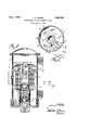
- FIG. 1 is a vertical substantially mid-sectional view of a preferred embodiment of the invention, showing the electrical circuit in diagrammatic form;
- FIG. 2 is a section taken substantially on the line 22 of FIG. 1.
- FIG. 1 of the drawing there is illustrated an electromagnetic pump comprising a non-magnetic cylinder 1 in which a hollow magnetic piston plunger 2 is slidably mounted.
- a spring 3 is arranged to normally hold the piston against a yielding stop member 4, and an electromagnet 5 surrounding the cylinder 1, is arranged when energized to draw the piston 2 down against the force of the spring 3.
- the cylinder *1 is mounted centrally in a casing 6 of magnetizable material by means of pole pieces 7, 8.
- the casing 6 forms an inlet chamber 9 and an outlet chamber 11, and check valves 12 and 13 connected to the cylinder 1 and piston 2 respectively, cause reciprocation of the piston to transfer liquid from the inlet chamber to the outlet chamber.
- Means are provided for intermittently energizing the electro-magnet 5 to cause reciprocation of the piston.
- this means comprises a battery 14 grounded at 15 and connected through a manual switch 116 to the electro magnet 5, here indicated diagrammatically.
- the electro-magnet is connected by a lead 17 to a spring blade 21 mounted on the upper pole piece 7 as indicated at 22, but insulated therefrom.
- spring blade 21 carries a contact 23 which is normally in engagement with a contact 24 on a shorter and stiffer spring blade 25 which is also mounted on the upper pole piece 7 and is grounded thereon as indicated at 26.
- An armature member '27 formed of soft sheet iron is pivoted as shown at 28 on the upper pole piece 7 for horizontal movement toward and away from the pump cylinder 1.
- the armature 27 is in the form of a lever having its fulcrum at the pivot 28 and having its long arm 29 curved to conform to the exterior of the cylinder 1.
- the short arm 31 of the lever has a pin 32 of suitable non-conducting material fixed thereon in position to engage near the free end of the contact spring blade 21, whereby the pressure of the blade 21 on the pin 32 normally holds the long arm 29 of the armature away from the cylinder 1 and against a back stop 33 as illustrated.
- closure of the switch 16 causes energization of the coil 5 whereby the piston 2 is drawn down, cocking the spring 3.
- the concentration of flux from the electromagnet at the end of the piston becomes eifective to attract the arm 29 of lever 27 and thereby open contacts 23, 24.
- the collapse of the flux through the coil 5 then permits the pump spring 3 to accomplish the return or pumping stroke of the piston 2.
- the armature 27 is released, permitting contacts 23, 24 to close, whereupon the operation is repeated.
- an actuating mechanism for the control contacts of an electro-magnetic pump in which the operation of the contacts is a function of the stroke of the piston, although no permanent magnetic material is used to sense the movement of the piston in its cylinder.
- a reciprocating electromagnetic motor a vertically disposed non-magnetic cylinder; a magnetizable piston of low magnetic reluctance slidably mounted in the cylinder; a stop adjacent the upper extremity of the cylinder defining the normal position of the piston in the cylinder; yielding means urging the piston towards the stop; an electromagnet having an upper and lower pole piece surrounding the cylinder and piston and defining a spatial separation between the stop and the upper pole piece, said electromagnet arranged, when energized, to magnetize the piston and draw it into the electromagnet away from the stop with an end of the piston positioned in the spatial separation adjacent the upper pole piece; and means within the spatial separation actuated solely by the magnetic attraction of the end of the piston as the piston is magnetized by the electromagnet for controlling the energization of the electromagnet including a pair of resiliently supported normally closed contacts and a movable magnetizable armature in the form of a lever pivotally mounted for movement towards and away from the piston end as the end
- contact supports to open said contacts as the lever moves towards the piston end.
Description
INVENTOR (Ziand/C Parker Aug. 1, 1961 L. c. PARKER RECIPROCATING ELECTRO-MAGNETIC MOTOR Filed June 27, 1956 United States v Patent i 2,994,792 RECIPROCATING ELECTRO-MAGNETIC MOTOR Leland C. Parker, Elmira, N.Y., assignor to The Bendix Corporation, a corporation of Delaware Filed June 27, 1956, Ser. No. 594,232 2 Claims. (Cl. 310-18) The present invention relates to a reciprocating electromagnetic motor, and more particularly to a device of this type which is especially adapted for operation as a piston pump.
Piston type electrical fuel pumps such as shown for instance in the patent to Dickey et al. 2,472,067 have attained wu'de commercial acceptance, but in such a highly competitive field economies in material and fabrication, and improvements in operation are very important.
In devices of this kind as heretofore constructed, the control of the electro-magnet which actuates the pump piston has commonly been either by some device which is extraneous and independent of the movement of the piston, or by means of a permanent magnetic element which senses the movement of the piston, While the first form of control has certain advantages for some types of use, the second form is at present more prevalent in spite of the fact that the permanent magnetic element and its mounting means form important items of the cost of the device.
It is an object of the present invention to provide a novel device of this character which is simple and economical in construction and eflicient in operation.
It is another object to provide such a device incorporating an improved form of means for controlling the actuation of the pump piston.
It is another object to provide such a device in which the movement of the piston is employed to control the energization of the actuating means in a simple and effective manner without utilizing any permanent magnetic element.
Further objects and advantages will be apparent from the following description taken in connection with the accompanying drawing in which:
FIG. 1 is a vertical substantially mid-sectional view of a preferred embodiment of the invention, showing the electrical circuit in diagrammatic form; and
FIG. 2 is a section taken substantially on the line 22 of FIG. 1.
In FIG. 1 of the drawing there is illustrated an electromagnetic pump comprising a non-magnetic cylinder 1 in which a hollow magnetic piston plunger 2 is slidably mounted. A spring 3 is arranged to normally hold the piston against a yielding stop member 4, and an electromagnet 5 surrounding the cylinder 1, is arranged when energized to draw the piston 2 down against the force of the spring 3.
The cylinder *1 is mounted centrally in a casing 6 of magnetizable material by means of pole pieces 7, 8. The casing 6 forms an inlet chamber 9 and an outlet chamber 11, and check valves 12 and 13 connected to the cylinder 1 and piston 2 respectively, cause reciprocation of the piston to transfer liquid from the inlet chamber to the outlet chamber.
Means are provided for intermittently energizing the electro-magnet 5 to cause reciprocation of the piston. As best shown in FIG. 2, this means comprises a battery 14 grounded at 15 and connected through a manual switch 116 to the electro magnet 5, here indicated diagrammatically. The electro-magnet is connected by a lead 17 to a spring blade 21 mounted on the upper pole piece 7 as indicated at 22, but insulated therefrom. The
An armature member '27 formed of soft sheet iron is pivoted as shown at 28 on the upper pole piece 7 for horizontal movement toward and away from the pump cylinder 1. The armature 27 is in the form of a lever having its fulcrum at the pivot 28 and having its long arm 29 curved to conform to the exterior of the cylinder 1. The short arm 31 of the lever has a pin 32 of suitable non-conducting material fixed thereon in position to engage near the free end of the contact spring blade 21, whereby the pressure of the blade 21 on the pin 32 normally holds the long arm 29 of the armature away from the cylinder 1 and against a back stop 33 as illustrated. When the armature is drawn against the cylinder by the attraction of the magnetic flux of the piston 2, such movement causes the pin 32 to separate the contacts 23, 24 and thus deenergize the coil 5.
In operation, starting with the parts in the positions illustrated, closure of the switch 16 causes energization of the coil 5 whereby the piston 2 is drawn down, cocking the spring 3. When the top end of the piston has been thus moved down to substantially the level of the armature 27, the concentration of flux from the electromagnet at the end of the piston becomes eifective to attract the arm 29 of lever 27 and thereby open contacts 23, 24. The collapse of the flux through the coil 5 then permits the pump spring 3 to accomplish the return or pumping stroke of the piston 2. At the same time the armature 27 is released, permitting contacts 23, 24 to close, whereupon the operation is repeated.
It will be appreciated that there is here provided an actuating mechanism for the control contacts of an electro-magnetic pump in which the operation of the contacts is a function of the stroke of the piston, although no permanent magnetic material is used to sense the movement of the piston in its cylinder.
Although certain structure has been shown and described in detail it will be understood that changes may be made in the precise form and arrangement of the parts without departing from the spirit of the invention.
1 claim:
1. In a reciprocating electromagnetic motor; a vertically disposed non-magnetic cylinder; a magnetizable piston of low magnetic reluctance slidably mounted in the cylinder; a stop adjacent the upper extremity of the cylinder defining the normal position of the piston in the cylinder; yielding means urging the piston towards the stop; an electromagnet having an upper and lower pole piece surrounding the cylinder and piston and defining a spatial separation between the stop and the upper pole piece, said electromagnet arranged, when energized, to magnetize the piston and draw it into the electromagnet away from the stop with an end of the piston positioned in the spatial separation adjacent the upper pole piece; and means within the spatial separation actuated solely by the magnetic attraction of the end of the piston as the piston is magnetized by the electromagnet for controlling the energization of the electromagnet including a pair of resiliently supported normally closed contacts and a movable magnetizable armature in the form of a lever pivotally mounted for movement towards and away from the piston end as the end approaches the upper pole piece so as to be attracted towards the said piston end responsive to energization of the electromagnet, said lever having pin means operatively engaging one of the resilient Patented Aug. 1, 1961.
contact supports to open said contacts as the lever moves towards the piston end.
2. A reciprocating electromagnetic motor as set forth in claim 1 in which said resiliently supported contacts are mounted on spring cantilever arms normally pressing said contacts together, one of said arms being substantially stifier than the other, said means for opening the contacts being arranged to move the more limber arm away from the stiffer arm to open said contacts.
References Cited in the file of this patent UNITED STATES PATENTS FOREIGN PATENTS Great Britain Oct. 16, 1931
Priority Applications (1)
| Application Number | Priority Date | Filing Date | Title |
|---|---|---|---|
| US594232A US2994792A (en) | 1956-06-27 | 1956-06-27 | Reciprocating electro-magnetic motor |
Applications Claiming Priority (1)
| Application Number | Priority Date | Filing Date | Title |
|---|---|---|---|
| US594232A US2994792A (en) | 1956-06-27 | 1956-06-27 | Reciprocating electro-magnetic motor |
Publications (1)
| Publication Number | Publication Date |
|---|---|
| US2994792A true US2994792A (en) | 1961-08-01 |
Family
ID=24378080
Family Applications (1)
| Application Number | Title | Priority Date | Filing Date |
|---|---|---|---|
| US594232A Expired - Lifetime US2994792A (en) | 1956-06-27 | 1956-06-27 | Reciprocating electro-magnetic motor |
Country Status (1)
| Country | Link |
|---|---|
| US (1) | US2994792A (en) |
Cited By (6)
| Publication number | Priority date | Publication date | Assignee | Title |
|---|---|---|---|---|
| US3184622A (en) * | 1960-08-01 | 1965-05-18 | Edwards Company Inc | Bell striker assembly |
| US3248581A (en) * | 1963-03-14 | 1966-04-26 | Sperry Rand Corp | Oscillating electromagnetic motor with motion conversion means |
| US3400663A (en) * | 1967-03-09 | 1968-09-10 | Bendix Corp | Reciprocating plunger pump |
| US4169696A (en) * | 1977-10-12 | 1979-10-02 | Facet Enterprises, Inc. | High pressure fluid pump |
| US4306842A (en) * | 1978-06-28 | 1981-12-22 | Jidosha Kiki Co., Ltd. | Electromagnetic pumps |
| US4375941A (en) * | 1978-03-20 | 1983-03-08 | Child Frank W | Method and apparatus for pumping blood |
Citations (4)
| Publication number | Priority date | Publication date | Assignee | Title |
|---|---|---|---|---|
| GB359443A (en) * | 1930-02-10 | 1931-10-16 | Tecalemit Ltd | Improvements relating to electric pumps |
| US2474349A (en) * | 1946-02-11 | 1949-06-28 | Bendix Aviat Corp | Electromagnetic pump |
| US2481147A (en) * | 1947-09-18 | 1949-09-06 | Bendix Aviat Corp | Reciprocating electromagnetic motor |
| US2490505A (en) * | 1948-01-16 | 1949-12-06 | Pierce Governor Company Inc | Slapless magnetically reciprocable structure |
-
1956
- 1956-06-27 US US594232A patent/US2994792A/en not_active Expired - Lifetime
Patent Citations (4)
| Publication number | Priority date | Publication date | Assignee | Title |
|---|---|---|---|---|
| GB359443A (en) * | 1930-02-10 | 1931-10-16 | Tecalemit Ltd | Improvements relating to electric pumps |
| US2474349A (en) * | 1946-02-11 | 1949-06-28 | Bendix Aviat Corp | Electromagnetic pump |
| US2481147A (en) * | 1947-09-18 | 1949-09-06 | Bendix Aviat Corp | Reciprocating electromagnetic motor |
| US2490505A (en) * | 1948-01-16 | 1949-12-06 | Pierce Governor Company Inc | Slapless magnetically reciprocable structure |
Cited By (6)
| Publication number | Priority date | Publication date | Assignee | Title |
|---|---|---|---|---|
| US3184622A (en) * | 1960-08-01 | 1965-05-18 | Edwards Company Inc | Bell striker assembly |
| US3248581A (en) * | 1963-03-14 | 1966-04-26 | Sperry Rand Corp | Oscillating electromagnetic motor with motion conversion means |
| US3400663A (en) * | 1967-03-09 | 1968-09-10 | Bendix Corp | Reciprocating plunger pump |
| US4169696A (en) * | 1977-10-12 | 1979-10-02 | Facet Enterprises, Inc. | High pressure fluid pump |
| US4375941A (en) * | 1978-03-20 | 1983-03-08 | Child Frank W | Method and apparatus for pumping blood |
| US4306842A (en) * | 1978-06-28 | 1981-12-22 | Jidosha Kiki Co., Ltd. | Electromagnetic pumps |
Similar Documents
| Publication | Publication Date | Title |
|---|---|---|
| US2539547A (en) | Relay | |
| US3293516A (en) | Electromagnetically driven pumps, particularly fuel pumps | |
| US2994792A (en) | Reciprocating electro-magnetic motor | |
| GB1143805A (en) | ||
| US2765747A (en) | Reciprocating electromagnetic pump | |
| GB1040281A (en) | Improvements in or relating to electromagnetically actuated reciprocating pumps | |
| US3210041A (en) | Electromagnetic actuator | |
| US2691739A (en) | Reciprocatory electric motor | |
| US2430151A (en) | Electromagnetic motor | |
| US2481147A (en) | Reciprocating electromagnetic motor | |
| US2666153A (en) | Reciprocatory electric motor | |
| GB974087A (en) | Improvements in or relating to electromagnetically actuated reciprocating free piston pumps | |
| US2468343A (en) | Reciprocatory electromagnetic motor | |
| US1690348A (en) | Electromagnetic motor | |
| US3273505A (en) | Electrically operated fuel pump | |
| US2474349A (en) | Electromagnetic pump | |
| GB884280A (en) | Improvements in or relating to electromagnetic relays | |
| US2533164A (en) | Electromagnetic pump | |
| US2716381A (en) | Reciprocating electro-magnetic pump | |
| US2717553A (en) | Electromagnetic fuel pump | |
| US2461501A (en) | Electromagnetic pump | |
| US2490505A (en) | Slapless magnetically reciprocable structure | |
| US2458770A (en) | Electrically actuated pump | |
| GB1434938A (en) | Solenoid switches | |
| US3361069A (en) | Electronically controlled electromagnetic pump system |