US2994084A - Scanning antenna - Google Patents
Scanning antenna Download PDFInfo
- Publication number
- US2994084A US2994084A US400477A US40047753A US2994084A US 2994084 A US2994084 A US 2994084A US 400477 A US400477 A US 400477A US 40047753 A US40047753 A US 40047753A US 2994084 A US2994084 A US 2994084A
- Authority
- US
- United States
- Prior art keywords
- guide
- antenna
- wave
- horn
- magnetic field
- Prior art date
- Legal status (The legal status is an assumption and is not a legal conclusion. Google has not performed a legal analysis and makes no representation as to the accuracy of the status listed.)
- Expired - Lifetime
Links
Images

Classifications
-
- H—ELECTRICITY
- H01—ELECTRIC ELEMENTS
- H01Q—ANTENNAS, i.e. RADIO AERIALS
- H01Q3/00—Arrangements for changing or varying the orientation or the shape of the directional pattern of the waves radiated from an antenna or antenna system
- H01Q3/26—Arrangements for changing or varying the orientation or the shape of the directional pattern of the waves radiated from an antenna or antenna system varying the relative phase or relative amplitude of energisation between two or more active radiating elements; varying the distribution of energy across a radiating aperture
- H01Q3/2664—Arrangements for changing or varying the orientation or the shape of the directional pattern of the waves radiated from an antenna or antenna system varying the relative phase or relative amplitude of energisation between two or more active radiating elements; varying the distribution of energy across a radiating aperture electrically moving the phase centre of a radiating element in the focal plane of a focussing device
Definitions
- This invention relates to directional antenna systems for high frequency electromagnetic wave energy and more particularly to antenna systems of the type for which the radiating direction of a transmitted wave from the antenna or the responsive direction for a received wave at the antenna may be easily varied in the process known as scanning.
- conventional directive antenna structures are modified by the inclusion of elements of polarized gyromagnetic material.
- This material is capable of producing a displacement of the field pattern of electromagnetic wave energy within the antenna that is proportional to the strength of the applied polarizing field.
- this material is located within the feed element of a reflectortype antenna so that the wave energy is displaced to one side or the other of the reflector focus.
- the feed may be continuous 1y shifted between these positions by electrically varying the polarizing field.
- the gyromagnetic material is located within a horn-type antenna of conventional design.
- the field pattern of the electromagnetic wave energy within the horn is shifted from one side thereof to another in proportion to the strength of the magnetic field applied to the gyromagnetic material.
- a special feature of the present invention resides in the non-reciprocal nature of the displacement.
- the shift or displacement of a wave received at the antenna is the reverse of the shift of a transmitted wave. This property is particularly useful in a radio relay system in which the desired direction of transmission from the antenna is not the same as the direction required for reception.
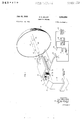
- FIG. 1 is a perspective view of an embodiment of the invention showing a reflector-type antenna including a gyromagnetic element within the feed guide portion of the antenna;
- FIG. 2 given by way of illustration, shows the magnetic field configuration of a dominant mode wave in the feed guide portion of FIG. 1;
- FIG. 3 is a perspective view of a second embodiment of the invention showing a horn-type antenna with the gyromagnetic element included directly within the horn portion of the antenna.
- a reflector-type scanning antenna is shown as an illustrative embodiment of the present invention.
- the feed portion of the antena comprises a section 11 of conductively bounded electrical transmission line for guiding wave energy which may be a rectangular wave guide of the metallic shield type having a wide internal cross-sectional dimension of at least one-half wavelength of the energy to be conducted thereby and a narrow dimension substantially one half of the wide dimension.
- One end of guide 11 is con nected to a suitable feed for vertically polarized waves in guide 11, which may comprise as illustrated, a degree bend 13 and rectangular wave guide 12.
- Guide 12 is in turn connected to a translating device 14 which may be a radio receiver, a transmitter, a radio receiver and transmitter connected together through a duplexing device, or a radar transceiver, depending upon the particular use to which the antenna is put.
- Facing aperture 15 is a conductive parabolic reflector 16 which is particularly illustrated as a concave paraboloidal mirror, but may, however, be a cylindrical parabolic reflector or a sectorial parabolic reflector.
- the focal point 17 of reflector 16 (or focal line in the case of the cylindrical reflector) is located in the plane of aperture 15 and substantially at the center thereof so that the main optical axis 18 of reflector 16 coincides with the longitudinal axis of guide .11.
- the size of reflector 16 will be somewhat larger in proportion to guide 11 than would appear from the illustrative drawing.
- means for producing a transverse displacement of the magnetic field pattern of wave energy is included within feed guide 11.
- guide 11 is partially filled in the region adjacent to aperture 15 by a polarized gyromagnetic medium or a medium having electrical and magnetic properties of the type derived from the mathematical analysis of D. Polder in Philosophical Magazine, January 1949, vol. 40, pages 99 through 115.
- guide 11 includes a pair of slab-like elements 19 and 20 located adjacent to the respectively opposite internal narrow walls of guide 11 and extending back from aperture 15 for several wavelengths.
- Elements 19 and 20 may have a thickness on the order of 15 percent of the wave-guide width and may be composed of any of the several ferromagnetic materials combined in a spinel structure.
- elements 19 and 20 may be made of nickel-zinc ferrite prepared in the manner described in a publication of C. L. Hogan, The Microwave Gyrator, in the Bell System Technical Journal, January 1952, and in his copending application Serial No.
- the ends of elements 19 and 20 are provided with wedge-like tapers, for example, tapers 22 and 23 of element 20, which on the aperture 15 end of guide 11 extend on beyond the conductive material of guide 11. These tapers are provided to prevent undue reflections of wave energy from a sharp discontinuity at the ends of elements 19 and 20.
- Elements 19 and 20 are biased in the same direction by a variable magnetic field applied at right angles to the direction of propagation of the wave energy in guide 11.
- this field may be supplied by a O-shaped magnetic core 24 having pole pieces 25 and 26, respectively, bearing upon the top and bottom wide Walls of guide 11 in the region of elements 19 and 20.
- Turns of wire 27 are wound around core 24 and connected through a reversing switch 28 to a source of magnetizing current selected by switch 29.
- the source of current comprises a direct current potential variable through positive and negative values as supplied by the combination of battery 30 and rheostat 31.
- This field may be supplied by an electrical solenoid with a metallic core of other suitable physical design, or by a solenoid without a core.
- FIG. 2 The displacement efiect of elements 19 and 20 upon wave energy propagated along guide 11 may most readily be understood by referring to explanatory FIG. 2 given for the purpose of illustration.
- FIG. 2 are shown representative loops 34 of the high frequency magnetic field of the dominant mode wave in the rectangular wave guide 11 of FIG. 1 at a particular instant of time.
- the arrows 36 and 37 indicate the forward and backward directions of propagation, respectively, of the wave in guide 1 1, and the arrows on the individual loops 34 indicate their polarity at any given point in the guide at the time illustrated.
- the lines 34 of magnetic intensity are loops which lie entirely in planes which are parallel to the wide dimension of guide 11. It will then be noted that at a point 38 on the left-hand side of center line 39 in guide 11 or at a point 40 on the right-hand side of center line 39, the magnetic intensity of the wave is circularly polarized as the wave propagates along guide 11. For a wave propagating in the forward direction, a counterclockwise rotating component of the magnetic intensity is presented at point 38 and a clockwise rotating component at point 40. For propagation through guide 11 in the backward direction the circularly polarized components seen at points 38 and 40 will rotate in respectively opposite directions from those seen for the forward direction of propagation.
- Elements 19 and 20 of FIG. 1 are located in guide 11 to include the region represented by points 38 and 40 of FIG. 2. While these elements are demagnetized, the cross-sectional distribution of wave energy in guide 11 is symmetrical with the minimum of longitudinal magnetic field and the maximum of electrical intensity falling along the center line 39. However, as a biasing magnetic field is increased, the effect is to concentrate the lines of magnetic field into a given side of the guide as viewed in the direction in which the wave is propagating, or from another viewpoint, to displace the electrical field pattern of the Wave energy within the guide.
- pole piece 25 constitutes a north pole and pole piece 26 constitutes a south pole and for a wave propagating in the forward direction toward reflector 16
- a high permeability is presented to Wave components on the left side of guide 11 and a low permeability to wave components on the right.
- This difference concentrates the lines of magnetic field in guide 11 so that the maximum electrical field intensity falls along a line 41 displaced to the left-hand side of longitudinal axis 18.
- the maximum electrical intensity of this wave will fall along a line 42 displaced to the righthand side of axis 18.
- a component of the wave leaving aperture 15 follows a path such as represented by line 42 to the right of focal point 17 and will therefore be redirected into a major lobe as represented by vector 44.
- the major lobe of the antenna of FIG. 1 may be scanned over an angle in the horizontal plane or by setting the arm at a particular value the beam may be permanently directed along any path within this angle.
- the antenna of FIG. 1 is ideally suited for use in a radio relay system of the type in which successive stations are arranged along a zig-zag path, rather than being placed in a straight line, so that overcarry from a preceding station will not cause interference.
- the main axis 18 of reflector 16 is directed midway between the succeeding receiving station and the preceding transmitting station. The strength of the magnetic field is adjusted so that the angle of maximum effectiveness of the antenna for receiving is directed toward the transmitting station which will automatically direct the transmitted beam toward the successive receiving station.
- the beam may be continuously scanned by supplying the magnetic field from a sawtooth generator 32.
- the sawtooth wave should be centered about zero so that the field of solenoid 27 is reversed in polarity during each sweep. If it is desired to receive a signal from the same angle as that of transmission, for example, if it is desired to receive the reflection from a target in a radar system, it is necessary to reverse the field following transmission and prior to reception.
- Reversing switch 28 which may be synchronized with the duplexer or TR-box in such a system is provided for this purpose.
- a further application of the invention is represented by the third position of switch 29 which connects solenoid 27 to a tracking control circuit 33 which produces a current related in a predetermined manner to the received signal.
- the maximum receiving direction of the antenna may always be directed toward the apparent direction of the received signal.
- guide 11 may be tilted out of the main reflection path from surface 16 or surface 16 may be provided with a particularly defined curvature in accordance with practices well known in the art.
- FIG. 1 While the ferromagnetic elements of FIG. 1 have been described as included within an antenna feed unit, it should be apparent that the combination shown in FIG. 1 will serve as a primary antenna for limited scanning by eliminating reflector 16 and employing guide 11 as a primary antenna unit.
- a primary antenna which is, however, capable of a substantially greater angle of scan is shown in FIG. 3.
- a horn 50 includes a pair of trapezoidal walls 46 and 47, shown as the top and bottom walls, respectively, which are substantially parallel, oppositely disposed conductive sheets, and a pair of rectangularly shaped sides 48 and 49 which flare smoothly and continuously from the throat 51 to the radiating aperture 52 of horn 50.
- Throat 51 has a cross section which is rectangular in shape and may have a wide dimension of at least one-half wavelength and a narrow dimension substantially one half the wide dimension.
- a section of rectangular wave guide 53 connects throat 51 to the translating device 54.
- the invention is, however, applicable to horns of which the sides are of varying flare, such as exponential or hyperbolic, and also to horns in which all four sides flare, such as the pyramidal horn.
- a pair of elements 55 and 56 which are similar in composition and operation to elements 19 and 20 of FIG. 1 are included within horn 50.
- Elements 55 and 56 are located adjacent the internal faces of rectangular walls 48 and 49, respectively, extending transversely between the parallel walls 46 and 47, and running longitudinally from throat 51 to aperture 52.
- the ends of elements 55 and 56 immediately adjacent to aperture 52 at one end and throat 51 at the other are provided with smooth tapers running to a fine edge, such as tapers 57 and 58 of element 56, to prevent undue reflections from these ends.
- the ends adjacent aperture 52 extend beyond the conductive material of horn 50.
- each of elements 55 and 56 increases toward aperture 52 in proportion to the taper between walls 48 and 49 so that a substantially constant percentage of horn 50 is occupied by elements 55 and 56 along the length of horn 50.
- a biasing magnetic field is applied to elements 55 and 56 by a C-shaped magnetic core 59, similar to structure 24 of FIG. 1, which extends across the top and bottom walls 46 and 47 of horn 50.
- Turns of wire 60 are connected to a source of magnetizing current which may be derived from any of the several sources described with reference to FIG. 1.
- the operation of the antenna of FIG. 3 is similar to the operation of the feed portion of the antenna of FIG. 1.
- the intensity of the biasing magnetic field applied to elements 55 and 56 is zero, the field distribution of the wave energy leaving aperture 52 is substantially centered around the longitudinal center line 61 of horn 50.
- the top pole of magnetic core 59 is north and the lower pole is south the field pattern of a forward traveling transmitted wave is progressively displaced to the left toward wall 49 as the wave travels the longitudinal extent of horn 50 so that the wave emerges with its field pattern centered about an axis such as 62 and its direction of propagation in general is represented by arrow 63.
- the transmitted wave will be centered about an axis such as 64 and have a direction of propagation such as rep resented by arrow 65.
- the magnetic field displacement underlying the principles rof the invention has been obtained by two slab-like elements of gyromagnetic material located adjacent to either narrow wall of the guiding structure. It should be noted, however, that a single element on either side would produce a displacement of the same sort except that the displacement obtained by a single element would be somewhat smaller than that obtained with two elements.
- the element may be moved away from the narrow wall so long as an asymmetrical relation in the field pattern of the energy is maintained.
- the guiding structure could be completely filled with the material, but this may increase unnecessarily the amount of loss introduced by the dielectric of the ferromagnetic material and also would necessitate reducing the cross section of the structure to avoid the support of unwanted higher order modes of propagation.
- Other alternative embodiments for obtaining a satisfactory field displacement in general are disclosed in my copending application Serial No. 371,437, filed July 31, 1953, now United States Patent 2,849,683 issued August- 26, 1958.
- a first hollow conductive electromagnetic wave energy guiding structure a source of linearly polarized wave energy connected to one end of said structure, and means for coupling said energy from said structure into space
- said means including a second hollow conductive electromagnetic wave energy guiding structure coupled to the other end of said first structure and having an open end for radiating said energy into space, said second structure being partially filled with gyromagnetic material disposed in the path of said wave energy and extending from said open end toward said other end of said first structure, and means for applying a magnetic field of varying strength to said material in a direction parallel to said linear polarization.
- a first conductively bounded electromagnetic wave energy guiding structure having two ends, feed means for electromagnetic wave energy connected to one end of said first structure, means for coupling said energy from said structure into space connected to the other end of said first structure, said coupling means having an aperture for emitting and collecting electromagnetic wave energy having a solely transverse electric field pattern and a region of maximum electric intensity, at least one element of gyromagnetic material extending within said coupling means from a location adjacent to said aperture toward the location of the connection of said first structure and said coupling means and in a region of electric intensity substantially less than said maximum by an amount suflicient to materially displace the transverse distribution of said electric intensity, and means for applying a magnetic field of variable strength to said element.
- Said coupling means includes an open ended rectangular wave guide and wherein said aperture is the open end of said rectangular wave guide and said element is slab-like and extends longitudinally in said guide adjacent a narrow wall thereof.
- said coupling means includes a concave reflector of conductive material, said reflector facing said open end with a focus positioned in the plane of said open end.
- said coupling means is an electromagnetic horn and wherein said element is slab-like and extends from the mouth of said horn to the throat thereof.
- said means for applying a magnetic field comprises a solenoid having a magnetic path which passes through said element perpendicular to the direction of propagation of said wave energy through said coupling means,
- said solenoid being fed by a current of variable sense and magnitude.
- An electromagnetic wave antenna comprising a conductively bounded wave guide having an open end for emitting and collecting electromagnetic wave energy, a concave reflector facing said open end, said reflector having a focus at substantially the center of said open end, and means included in said guide for displacing the field pattern of said wave energy to one side of said focal point, said means comprising a polarized element of gyromagnetic material located in said guide to include the regions of circularly polarized components of the magnetic field of wave energy in said guide.
- An electromagnetic antenna comprising a horn of conductive material having a throat, a pair of oppositely disposed flaring sides, and a pair of oppositely disposed substantially parallel sides substantially normal to said flaring sides, feed means positioned in the throat of said horn, at least one element of gyromagnetic material included within said horn and located therein asymmetrically with respect to the longitudinal center line of said horn, and means for applying a magnetic field to said element.
- Kales et al. A Nonrecipnocal Microwave Component, pp. 816-817, Journal of Applied Physics, vol. 24, July 1953.
Landscapes
- Variable-Direction Aerials And Aerial Arrays (AREA)
Description
July 25, 1961 s. E. MILLER 2,994,084
SCANNING ANTENNA Fil d D e ee 28 195' 2 Sheets-Sheet 1 TRA C K lNG CONTROL C IRC U/ T 34w room SWEEP GENERATOR TRANSLAT/NG DE VICE INVENTOR S. E. M/L L E R A 7' TORNE July 25, 1961 s. E. MILLER SCANNING ANTENNA Filed Dec. 28, 1953 2 Sheets-Sheet 2 INI/ENTOR 5.5. MILLER k ATTORNEY United States Patent i 2,994,084 SCANNING ANTENNA Stewart E. Miller, Middletown, N.J., assignor to Bell Telephone Laboratories, Incorporated, New York, N.Y., a corporation of New York Filed Dec. 28, 1953, Ser. No. 400,477 12 Claims. (Cl. 343783) This invention relates to directional antenna systems for high frequency electromagnetic wave energy and more particularly to antenna systems of the type for which the radiating direction of a transmitted wave from the antenna or the responsive direction for a received wave at the antenna may be easily varied in the process known as scanning.
By far the great majority of scanning antennas heretofore employed in microwave transmission systems depend in one way or another upon mechanically moving parts to effect the scanning operation. These systems are therefore restricted by the many difliculties inherent in any mechanical arrangement. Other alternatives have been ofl ered by antenna systems employing an array of many radiating elements to which energy is fed with varying relative phase relationships to eflect the scanning. The latter systems, however, sufler from a lack of compactness and simplicity.
It is therefore an object of the present invention to control accurately by electrical means the direction of effectiveness of an electromagnetic wave antenna.
It is a further object of the invention to provide a microwave antenna of simple and compact construction which may be scanned over an angle by electrical means without the necessity of mechanical movement of any of its component parts.
In accordance with the preferred embodiments of the invention to be described in detail hereinafter, conventional directive antenna structures are modified by the inclusion of elements of polarized gyromagnetic material. This material is capable of producing a displacement of the field pattern of electromagnetic wave energy within the antenna that is proportional to the strength of the applied polarizing field. In one embodiment, this material is located within the feed element of a reflectortype antenna so that the wave energy is displaced to one side or the other of the reflector focus. As in the mechanical system of the prior art as represented, for example, by Patent 2,409,183, granted October 15, 1946, to A. C. Beck, a small shift of the fed energy away from the focus results in a relatively larger deflection of the major lobe of the reflected beam. However, in the embodiment of the present invention, the feed may be continuous 1y shifted between these positions by electrically varying the polarizing field.
In another embodiment of the present invention, the gyromagnetic material is located within a horn-type antenna of conventional design. As in the feed of the embodiment described above, the field pattern of the electromagnetic wave energy within the horn is shifted from one side thereof to another in proportion to the strength of the magnetic field applied to the gyromagnetic material.
A special feature of the present invention resides in the non-reciprocal nature of the displacement. As will be discussed in detail hereinafter, the shift or displacement of a wave received at the antenna is the reverse of the shift of a transmitted wave. This property is particularly useful in a radio relay system in which the desired direction of transmission from the antenna is not the same as the direction required for reception.
These and other objects and features, the nature of the present invention and its advantages, will appear more Patented July 25, 1961 fully upon consideration of the several illustrative embodiments now to be described in conection with the accompanying drawings in which:
FIG. 1 is a perspective view of an embodiment of the invention showing a reflector-type antenna including a gyromagnetic element within the feed guide portion of the antenna;
FIG. 2, given by way of illustration, shows the magnetic field configuration of a dominant mode wave in the feed guide portion of FIG. 1; and
FIG. 3 is a perspective view of a second embodiment of the invention showing a horn-type antenna with the gyromagnetic element included directly within the horn portion of the antenna.
Referring more specifically to FIG. 1, a reflector-type scanning antenna is shown as an illustrative embodiment of the present invention. The feed portion of the antena comprises a section 11 of conductively bounded electrical transmission line for guiding wave energy which may be a rectangular wave guide of the metallic shield type having a wide internal cross-sectional dimension of at least one-half wavelength of the energy to be conducted thereby and a narrow dimension substantially one half of the wide dimension. One end of guide 11 is con nected to a suitable feed for vertically polarized waves in guide 11, which may comprise as illustrated, a degree bend 13 and rectangular wave guide 12. Guide 12 is in turn connected to a translating device 14 which may be a radio receiver, a transmitter, a radio receiver and transmitter connected together through a duplexing device, or a radar transceiver, depending upon the particular use to which the antenna is put.
The other end of guide 11 is open to electromagnetic wave energy thereby constituting a radiating aperture 15. Facing aperture 15 is a conductive parabolic reflector 16 which is particularly illustrated as a concave paraboloidal mirror, but may, however, be a cylindrical parabolic reflector or a sectorial parabolic reflector. In either event, the focal point 17 of reflector 16 (or focal line in the case of the cylindrical reflector) is located in the plane of aperture 15 and substantially at the center thereof so that the main optical axis 18 of reflector 16 coincides with the longitudinal axis of guide .11. In practice the size of reflector 16 will be somewhat larger in proportion to guide 11 than would appear from the illustrative drawing.
In accordance with the invention, means for producing a transverse displacement of the magnetic field pattern of wave energy is included within feed guide 11. In particular, guide 11 is partially filled in the region adjacent to aperture 15 by a polarized gyromagnetic medium or a medium having electrical and magnetic properties of the type derived from the mathematical analysis of D. Polder in Philosophical Magazine, January 1949, vol. 40, pages 99 through 115. As illustrated by way of example in FIG. 1, guide 11 includes a pair of slab-like elements 19 and 20 located adjacent to the respectively opposite internal narrow walls of guide 11 and extending back from aperture 15 for several wavelengths. Elements 19 and 20 may have a thickness on the order of 15 percent of the wave-guide width and may be composed of any of the several ferromagnetic materials combined in a spinel structure. As an example, they may comprise an iron oxide with a small quantity of one or more bivalent metals, such as nickel, magnesium, zinc, manganese or other simi lar material, in which the other metals combine with the iron oxide in a spinel structure. This material is known as a ferromagnetic spinel or a ferrite. Frequently, these materials are first powdered and then molded with a small percentage of plastic material, such as Teflon or polystyrene. As a specific example, elements 19 and 20 may be made of nickel-zinc ferrite prepared in the manner described in a publication of C. L. Hogan, The Microwave Gyrator, in the Bell System Technical Journal, January 1952, and in his copending application Serial No. 252,432 filed October 22, 1951, now United States Patent 2,748,353, issued May 29, 1956. The ends of elements 19 and 20 are provided with wedge-like tapers, for example, tapers 22 and 23 of element 20, which on the aperture 15 end of guide 11 extend on beyond the conductive material of guide 11. These tapers are provided to prevent undue reflections of wave energy from a sharp discontinuity at the ends of elements 19 and 20.
The displacement efiect of elements 19 and 20 upon wave energy propagated along guide 11 may most readily be understood by referring to explanatory FIG. 2 given for the purpose of illustration. In FIG. 2 are shown representative loops 34 of the high frequency magnetic field of the dominant mode wave in the rectangular wave guide 11 of FIG. 1 at a particular instant of time. The arrows 36 and 37 indicate the forward and backward directions of propagation, respectively, of the wave in guide 1 1, and the arrows on the individual loops 34 indicate their polarity at any given point in the guide at the time illustrated.
It will be noted that the lines 34 of magnetic intensity are loops which lie entirely in planes which are parallel to the wide dimension of guide 11. It will then be noted that at a point 38 on the left-hand side of center line 39 in guide 11 or at a point 40 on the right-hand side of center line 39, the magnetic intensity of the wave is circularly polarized as the wave propagates along guide 11. For a wave propagating in the forward direction, a counterclockwise rotating component of the magnetic intensity is presented at point 38 and a clockwise rotating component at point 40. For propagation through guide 11 in the backward direction the circularly polarized components seen at points 38 and 40 will rotate in respectively opposite directions from those seen for the forward direction of propagation.
Thus, in FIG. 1 when pole piece 25 constitutes a north pole and pole piece 26 constitutes a south pole and for a wave propagating in the forward direction toward reflector 16, a high permeability is presented to Wave components on the left side of guide 11 and a low permeability to wave components on the right. This difference concentrates the lines of magnetic field in guide 11 so that the maximum electrical field intensity falls along a line 41 displaced to the left-hand side of longitudinal axis 18. When the magnetic field is reversed from the polarities defined above, the maximum electrical intensity of this wave will fall along a line 42 displaced to the righthand side of axis 18. Conversely, since a wave propagating in guide 11 in the backward direction will have circularly polarized components which rotate in respectively opposite directions from those experienced for the forward direction of propagation, the wave propagating in the backward direction will be displaced from center line 18 for given directions of applied field in directions respectively opposite to those defined for the forward direction of propagation.
Thus, with switch 28 closed in its up position and switch 29 set at the position shown on FIG. 1 and with the arm of rheostat 31 set in its center position, the vertically polarized wave energy leaving aperture 15 will be centered about the focal point 17 of reflector 16 and a major lobe will therefore be reflected by surface 16 composed of components traveling substantially parallel to axis 18. When the arm of rheostat 31 is moved toward the positive pole of source 30, a component of the wave leaving aperture 15 follows a path such as represented by line 41 to the left of the focal point 17 and is therefore redirected by reflector 16 at an acute angle to axis 18 into a major lobe having its maximum intensity to the right of axis 18 as represented by vector 43. Similarly, when the arm of rheostat 31 is moved toward the negative pole of source 30, a component of the wave leaving aperture 15 follows a path such as represented by line 42 to the right of focal point 17 and will therefore be redirected into a major lobe as represented by vector 44. By moving the arm of rheostat 31 between successively positive and negative values the major lobe of the antenna of FIG. 1 may be scanned over an angle in the horizontal plane or by setting the arm at a particular value the beam may be permanently directed along any path within this angle.
Maximum effectiveness for a received signal will, however, lie on the opposite side of axis 18 for a given magnetic field from the transmitting direction specified. Thus, the antenna of FIG. 1 is ideally suited for use in a radio relay system of the type in which successive stations are arranged along a zig-zag path, rather than being placed in a straight line, so that overcarry from a preceding station will not cause interference. In such a system the main axis 18 of reflector 16 is directed midway between the succeeding receiving station and the preceding transmitting station. The strength of the magnetic field is adjusted so that the angle of maximum effectiveness of the antenna for receiving is directed toward the transmitting station which will automatically direct the transmitted beam toward the successive receiving station.
In applying the invention to a system such as radar the beam may be continuously scanned by supplying the magnetic field from a sawtooth generator 32. For maximum scanning the sawtooth wave should be centered about zero so that the field of solenoid 27 is reversed in polarity during each sweep. If it is desired to receive a signal from the same angle as that of transmission, for example, if it is desired to receive the reflection from a target in a radar system, it is necessary to reverse the field following transmission and prior to reception. Reversing switch 28 which may be synchronized with the duplexer or TR-box in such a system is provided for this purpose.
A further application of the invention is represented by the third position of switch 29 which connects solenoid 27 to a tracking control circuit 33 which produces a current related in a predetermined manner to the received signal. Thus, the maximum receiving direction of the antenna may always be directed toward the apparent direction of the received signal.
It is apparent that any of the several techniques employed in conventional antennas to eliminate the shadow of the feed mechanism may be employed in the present invention. For example, guide 11 may be tilted out of the main reflection path from surface 16 or surface 16 may be provided with a particularly defined curvature in accordance with practices well known in the art.
While the ferromagnetic elements of FIG. 1 have been described as included within an antenna feed unit, it should be apparent that the combination shown in FIG. 1 will serve as a primary antenna for limited scanning by eliminating reflector 16 and employing guide 11 as a primary antenna unit. A primary antenna which is, however, capable of a substantially greater angle of scan is shown in FIG. 3.
In FIG. 3 the principles of the invention are applied to a sectorial horn-type antenna. In accordance with conventional practice a horn 50 includes a pair of trapezoidal walls 46 and 47, shown as the top and bottom walls, respectively, which are substantially parallel, oppositely disposed conductive sheets, and a pair of rectangularly shaped sides 48 and 49 which flare smoothly and continuously from the throat 51 to the radiating aperture 52 of horn 50. Throat 51 has a cross section which is rectangular in shape and may have a wide dimension of at least one-half wavelength and a narrow dimension substantially one half the wide dimension. A section of rectangular wave guide 53 connects throat 51 to the translating device 54. The invention is, however, applicable to horns of which the sides are of varying flare, such as exponential or hyperbolic, and also to horns in which all four sides flare, such as the pyramidal horn.
In accordance with the invention, a pair of elements 55 and 56 which are similar in composition and operation to elements 19 and 20 of FIG. 1 are included within horn 50. Elements 55 and 56 are located adjacent the internal faces of rectangular walls 48 and 49, respectively, extending transversely between the parallel walls 46 and 47, and running longitudinally from throat 51 to aperture 52. The ends of elements 55 and 56 immediately adjacent to aperture 52 at one end and throat 51 at the other are provided with smooth tapers running to a fine edge, such as tapers 57 and 58 of element 56, to prevent undue reflections from these ends. As in FIG. 1, the ends adjacent aperture 52 extend beyond the conductive material of horn 50. Except for these end taper portions the thickness of each of elements 55 and 56 increases toward aperture 52 in proportion to the taper between walls 48 and 49 so that a substantially constant percentage of horn 50 is occupied by elements 55 and 56 along the length of horn 50. A biasing magnetic field is applied to elements 55 and 56 by a C-shaped magnetic core 59, similar to structure 24 of FIG. 1, which extends across the top and bottom walls 46 and 47 of horn 50. Turns of wire 60 are connected to a source of magnetizing current which may be derived from any of the several sources described with reference to FIG. 1.
The operation of the antenna of FIG. 3 is similar to the operation of the feed portion of the antenna of FIG. 1. Thus, when the intensity of the biasing magnetic field applied to elements 55 and 56 is zero, the field distribution of the wave energy leaving aperture 52 is substantially centered around the longitudinal center line 61 of horn 50. When the top pole of magnetic core 59, however, is north and the lower pole is south the field pattern of a forward traveling transmitted wave is progressively displaced to the left toward wall 49 as the wave travels the longitudinal extent of horn 50 so that the wave emerges with its field pattern centered about an axis such as 62 and its direction of propagation in general is represented by arrow 63. If the field is reversed, the transmitted wave will be centered about an axis such as 64 and have a direction of propagation such as rep resented by arrow 65.
In the preceding embodiments the magnetic field displacement underlying the principles rof the invention has been obtained by two slab-like elements of gyromagnetic material located adjacent to either narrow wall of the guiding structure. It should be noted, however, that a single element on either side would produce a displacement of the same sort except that the displacement obtained by a single element would be somewhat smaller than that obtained with two elements. The element may be moved away from the narrow wall so long as an asymmetrical relation in the field pattern of the energy is maintained. Also, the guiding structure could be completely filled with the material, but this may increase unnecessarily the amount of loss introduced by the dielectric of the ferromagnetic material and also would necessitate reducing the cross section of the structure to avoid the support of unwanted higher order modes of propagation. Other alternative embodiments for obtaining a satisfactory field displacement in general are disclosed in my copending application Serial No. 371,437, filed July 31, 1953, now United States Patent 2,849,683 issued August- 26, 1958.
In all cases it is understood that the above described arrangements are illustrative of a small number of the many possible specific embodiments which can represent applications of the principles of the invention. Numerous and varied other arrangements can readily be devised in accordance with these principles by those skilled in the art without departing from the spirit and scope of the invention.
What is claimed is:
1. In combination, a first hollow conductive electromagnetic wave energy guiding structure, a source of linearly polarized wave energy connected to one end of said structure, and means for coupling said energy from said structure into space, said means including a second hollow conductive electromagnetic wave energy guiding structure coupled to the other end of said first structure and having an open end for radiating said energy into space, said second structure being partially filled with gyromagnetic material disposed in the path of said wave energy and extending from said open end toward said other end of said first structure, and means for applying a magnetic field of varying strength to said material in a direction parallel to said linear polarization.
2. A first conductively bounded electromagnetic wave energy guiding structure having two ends, feed means for electromagnetic wave energy connected to one end of said first structure, means for coupling said energy from said structure into space connected to the other end of said first structure, said coupling means having an aperture for emitting and collecting electromagnetic wave energy having a solely transverse electric field pattern and a region of maximum electric intensity, at least one element of gyromagnetic material extending within said coupling means from a location adjacent to said aperture toward the location of the connection of said first structure and said coupling means and in a region of electric intensity substantially less than said maximum by an amount suflicient to materially displace the transverse distribution of said electric intensity, and means for applying a magnetic field of variable strength to said element.
3. A first conductively bounded electromagnetic wave energy guiding structure, feed means for wave energy connected to one end of said structure, and means for coupling said energy from said structure into space connected to the other end of said structure, said coupling means comprising a second conductively bounded electromagnetic wave energy guiding structure having an aperture for emitting and collecting electromagnetic wave energy, at least one element of gynomagnetic material extending within said second structure from a location within said aperture toward the location of the connection of said first structure and said coupling means, and means for applying a magnetic field of variable strength to said element in a direction transverse to the direction of propagation of said energy.
i "'43 The combination according to claim 2, wherein Said coupling means includes an open ended rectangular wave guide and wherein said aperture is the open end of said rectangular wave guide and said element is slab-like and extends longitudinally in said guide adjacent a narrow wall thereof.
5. The combination according to claim 4 wherein said coupling means includes a concave reflector of conductive material, said reflector facing said open end with a focus positioned in the plane of said open end.
6. The combination according to claim 2, wherein said coupling means is an electromagnetic horn and wherein said element is slab-like and extends from the mouth of said horn to the throat thereof.
7. The combination according to claim 6, wherein said horn is flaring in at least one dimension from the throat to the mouth thereof and wherein the thickness of said slab is tapered in proportion to the flare of said horn.
8. The combination according to claim 7 including a pair of said elements, each of said elements being located adjacent respectively opposite walls of said horn.
9. The combination according to claim 2, wherein said element is made of a ferrite.
10. The combination according to claim 2, wherein said means for applying a magnetic field comprises a solenoid having a magnetic path which passes through said element perpendicular to the direction of propagation of said wave energy through said coupling means,
said solenoid being fed by a current of variable sense and magnitude.
11. An electromagnetic wave antenna comprising a conductively bounded wave guide having an open end for emitting and collecting electromagnetic wave energy, a concave reflector facing said open end, said reflector having a focus at substantially the center of said open end, and means included in said guide for displacing the field pattern of said wave energy to one side of said focal point, said means comprising a polarized element of gyromagnetic material located in said guide to include the regions of circularly polarized components of the magnetic field of wave energy in said guide.
12. An electromagnetic antenna comprising a horn of conductive material having a throat, a pair of oppositely disposed flaring sides, and a pair of oppositely disposed substantially parallel sides substantially normal to said flaring sides, feed means positioned in the throat of said horn, at least one element of gyromagnetic material included within said horn and located therein asymmetrically with respect to the longitudinal center line of said horn, and means for applying a magnetic field to said element.
References Cited in the file of this patent UNITED STATES PATENTS 2,644,930 Luhrs July 7, 1953 2,768,354 Hogan Oct. 23, 1956 2,774,067 Bollinger Dec. 11, 1956 2,849,685 Weiss Aug. 26, 1958 FOREIGN PATENTS 678,874 Great Britain July 2, 1952 OTHER REFERENCES Sakiotis: Ferrites in Microwaves, IRE, January 1953, pages 87-93.
Turner: A New Non-Reciprocal Waveguide Medium Using Ferrites, page 937, IRE Proceedings, vol. 41, No. 7, July 1953.
Kales et al.: A Nonrecipnocal Microwave Component, pp. 816-817, Journal of Applied Physics, vol. 24, July 1953.
Electronics Magazine, June 1952, pages 156-l66.
The Ferromagnetic Farraday Effect at Microwave Frequencies and Its Applications, Hogan, Review of Modern Physics, vol. 25, No. 1, pages 253463, January 1953.
Priority Applications (1)
| Application Number | Priority Date | Filing Date | Title |
|---|---|---|---|
| US400477A US2994084A (en) | 1953-12-28 | 1953-12-28 | Scanning antenna |
Applications Claiming Priority (1)
| Application Number | Priority Date | Filing Date | Title |
|---|---|---|---|
| US400477A US2994084A (en) | 1953-12-28 | 1953-12-28 | Scanning antenna |
Publications (1)
| Publication Number | Publication Date |
|---|---|
| US2994084A true US2994084A (en) | 1961-07-25 |
Family
ID=23583780
Family Applications (1)
| Application Number | Title | Priority Date | Filing Date |
|---|---|---|---|
| US400477A Expired - Lifetime US2994084A (en) | 1953-12-28 | 1953-12-28 | Scanning antenna |
Country Status (1)
| Country | Link |
|---|---|
| US (1) | US2994084A (en) |
Cited By (9)
| Publication number | Priority date | Publication date | Assignee | Title |
|---|---|---|---|---|
| US3173146A (en) * | 1960-01-28 | 1965-03-09 | Washington Aluminum Co Inc | Dual polarized horn |
| US3222601A (en) * | 1962-07-10 | 1965-12-07 | Martin Marietta Corp | Antenna beam scanner |
| US3761938A (en) * | 1972-11-30 | 1973-09-25 | Us Army | Ferrite dipole antenna radiator |
| US3918064A (en) * | 1973-12-26 | 1975-11-04 | Cubic Corp | Wide angle antenna system |
| US4338609A (en) * | 1980-12-15 | 1982-07-06 | Rca Corporation | Short horn radiator assembly |
| US4573055A (en) * | 1981-12-09 | 1986-02-25 | Wright Thomas M B | Directionally sensitive receiving antenna |
| US4928109A (en) * | 1988-10-14 | 1990-05-22 | Cubic Defense Systems, Inc. | Modulated scanning antenna |
| US20060119358A1 (en) * | 2002-08-30 | 2006-06-08 | The University Of Queensland | Coil array for magnetic resonance imaging |
| WO2007132455A3 (en) * | 2006-05-11 | 2009-04-16 | Roadeye Flr General Partnershi | Vehicular microwave transceiver |
Citations (5)
| Publication number | Priority date | Publication date | Assignee | Title |
|---|---|---|---|---|
| GB678874A (en) * | 1950-06-16 | 1952-09-10 | Cooke S Finsbury Ltd | Improvements in the mounting of shelf-supporting and similar adjustable brackets |
| US2644930A (en) * | 1949-03-24 | 1953-07-07 | Gen Precision Lab Inc | Microwave polarization rotating device and coupling network |
| US2768354A (en) * | 1951-05-26 | 1956-10-23 | Bell Telephone Labor Inc | Gyromagnetic resonance type microwave mode converter |
| US2774067A (en) * | 1949-08-17 | 1956-12-11 | Rca Corp | Microwave scanning antenna system |
| US2849685A (en) * | 1953-08-17 | 1958-08-26 | Bell Telephone Labor Inc | Non-reciprocal multibranch wave guide component |
-
1953
- 1953-12-28 US US400477A patent/US2994084A/en not_active Expired - Lifetime
Patent Citations (5)
| Publication number | Priority date | Publication date | Assignee | Title |
|---|---|---|---|---|
| US2644930A (en) * | 1949-03-24 | 1953-07-07 | Gen Precision Lab Inc | Microwave polarization rotating device and coupling network |
| US2774067A (en) * | 1949-08-17 | 1956-12-11 | Rca Corp | Microwave scanning antenna system |
| GB678874A (en) * | 1950-06-16 | 1952-09-10 | Cooke S Finsbury Ltd | Improvements in the mounting of shelf-supporting and similar adjustable brackets |
| US2768354A (en) * | 1951-05-26 | 1956-10-23 | Bell Telephone Labor Inc | Gyromagnetic resonance type microwave mode converter |
| US2849685A (en) * | 1953-08-17 | 1958-08-26 | Bell Telephone Labor Inc | Non-reciprocal multibranch wave guide component |
Cited By (10)
| Publication number | Priority date | Publication date | Assignee | Title |
|---|---|---|---|---|
| US3173146A (en) * | 1960-01-28 | 1965-03-09 | Washington Aluminum Co Inc | Dual polarized horn |
| US3222601A (en) * | 1962-07-10 | 1965-12-07 | Martin Marietta Corp | Antenna beam scanner |
| US3761938A (en) * | 1972-11-30 | 1973-09-25 | Us Army | Ferrite dipole antenna radiator |
| US3918064A (en) * | 1973-12-26 | 1975-11-04 | Cubic Corp | Wide angle antenna system |
| US4338609A (en) * | 1980-12-15 | 1982-07-06 | Rca Corporation | Short horn radiator assembly |
| US4573055A (en) * | 1981-12-09 | 1986-02-25 | Wright Thomas M B | Directionally sensitive receiving antenna |
| US4928109A (en) * | 1988-10-14 | 1990-05-22 | Cubic Defense Systems, Inc. | Modulated scanning antenna |
| US20060119358A1 (en) * | 2002-08-30 | 2006-06-08 | The University Of Queensland | Coil array for magnetic resonance imaging |
| US7446528B2 (en) * | 2002-08-30 | 2008-11-04 | The University Of Queensland | Coil array for magnetic resonance imaging |
| WO2007132455A3 (en) * | 2006-05-11 | 2009-04-16 | Roadeye Flr General Partnershi | Vehicular microwave transceiver |
Similar Documents
| Publication | Publication Date | Title |
|---|---|---|
| US2511610A (en) | High-frequency electromagneticwave translating element | |
| Gloeckler | Phased array for millimeter wave frequencies | |
| US2849683A (en) | Non-reciprocal wave transmission | |
| US3219954A (en) | Surface wave transmission system for telecommunication and power transmission | |
| US2238770A (en) | High frequency electrical conductor or radiator | |
| US3001193A (en) | Circularly polarized antenna system | |
| US3268902A (en) | Dual frequency microwave aperturetype antenna providing similar radiation pattern on both frequencies | |
| US4613869A (en) | Electronically scanned array antenna | |
| US3369242A (en) | Inertialess electromagnetic wave scanner | |
| US2994084A (en) | Scanning antenna | |
| US3569974A (en) | Dual polarization microwave energy phase shifter for phased array antenna systems | |
| US3015100A (en) | Trough waveguide antennas | |
| US2921308A (en) | Surface wave device | |
| US3560976A (en) | Feed system | |
| Angelakos et al. | Radiation from ferrite-filled apertures | |
| US2849687A (en) | Non-reciprocal wave transmission | |
| US4691208A (en) | Ferrite waveguide scanning antenna | |
| US3445851A (en) | Polarization insensitive microwave energy phase shifter | |
| US3761938A (en) | Ferrite dipole antenna radiator | |
| US3238531A (en) | Electronically steerable narrow beam antenna system utilizing dipolar resonant plasma columns | |
| US2892191A (en) | Antenna system having a directionally variable radiation pattern | |
| US3310807A (en) | Apparatus for effecting the transmission of electromagnetic energy through a dense plasma | |
| US4746926A (en) | Phase scan antenna | |
| US3534374A (en) | High efficiency scanning millimeter wavelength antenna | |
| US3016535A (en) | Slotted waveguide antenna |