US2983020A - Calenders - Google Patents
Calenders Download PDFInfo
- Publication number
- US2983020A US2983020A US672749A US67274957A US2983020A US 2983020 A US2983020 A US 2983020A US 672749 A US672749 A US 672749A US 67274957 A US67274957 A US 67274957A US 2983020 A US2983020 A US 2983020A
- Authority
- US
- United States
- Prior art keywords
- pipe
- frame
- sleeve
- roller
- rollers
- Prior art date
- Legal status (The legal status is an assumption and is not a legal conclusion. Google has not performed a legal analysis and makes no representation as to the accuracy of the status listed.)
- Expired - Lifetime
Links
Images


Classifications
-
- B—PERFORMING OPERATIONS; TRANSPORTING
- B28—WORKING CEMENT, CLAY, OR STONE
- B28B—SHAPING CLAY OR OTHER CERAMIC COMPOSITIONS; SHAPING SLAG; SHAPING MIXTURES CONTAINING CEMENTITIOUS MATERIAL, e.g. PLASTER
- B28B21/00—Methods or machines specially adapted for the production of tubular articles
- B28B21/42—Methods or machines specially adapted for the production of tubular articles by shaping on or against mandrels or like moulding surfaces
- B28B21/50—Details of compression or compacting means
Definitions
- Another object of the present invention is to provide damping means to the central idler sleeve to any shock from the two reaction rollers and the compression roller and also prevent disequilibrium of pressure from the three rollers.
- Figure 1 is an end elevational view taken of the left side end of the pipe calendering machine
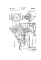
- Fig. 2 is a fragmentary vertical cross sectional view taken through one of the two hydraulic cylinders which actuates the compression roller and as viewed on line 2-2 of Fig. 4;
- Fig. 3 is a front elevational view of the pipe calendering machine with the compression roller broken away to look upon the pipe being formed;
- Fig. 4 is a top plan view of the pipe calendering machine
- FIG. 5 is an end elevational view taken of the right side end of the pipe calendering machine
- Fig. 6 is an enlarged horizontal sectional fragmentary view taken on line 66 of Fig. 7;
- Fig. 7 is a fragmentary vertical sectional view taken on line 7-7 of Fig. 4.
- This pipe calendering machine comprises a bed frame 1 which has bearing blocks or support frames 2 that are adjustably slidable fore and aft atop the respective bed frames 1 and guided by parallel tongue and groove guideways 3 in the surface of frame 2.
- Each of the bearing blocks or frames 2 holds a twoway fluid cylinder device 4 in which rides piston 5 which is integral with piston rod 6, Fig. 2. Said piston rod 6 is directly coupled to another slidable frame block 7 which is slidable upon the block or frame 2. Pressurized hydraulic fluid is used to move piston 5 in controlled directions by introducing hydraulic fluid in either ports 10 or 11.
- Frame 7 supports journal 12 of compression roller 9 in bearing 8 which is integral with the frame 7.
- the upper frames 7 on either end of compression roller 9 are connected together to work in unison through a laterally extending stabilizer device 13 having a moving pivot 14, a stationary pivot point 15 is journalled in frames 2 and a pivot connection 16 with upper slidable frame 7.
- the device generally comprises stabilizer shaft 15', end arms 14 and links 16'. The device 13 maintains parallel movement of the frames 7 and the alignment of compression roller 9 with other rollers to be mentioned.
- the frame .22 is slidable atop the bed frame 1, Fig. 5.
- Forked journal bearing 24 is pivotally connected by an offset pivot pin connection 23 upon upper end of the frame 22.
- a spring 26 between forked bearing 24 and slidable frame 22 absorbs any shock or unequal stresses borne by a mandril 25 that carries a perforated work or pipe sleeve 27.
- the pipe sleeve 27 makes contact with compression roller 9 and reaction rollers 28 and 29.
- man dril 25 is dropped into and supported by forked bearing frame 30.
- Base 33 of the frame 30 is slidable atop bracket 32 secured to bed frame 1.
- mandril 25 is hollow except for being plugged at the extreme right end.
- Mandril 25 is terminated at its extreme left end by an annular airtight swivel joint 36 that is coupled with flanged pipe fitting 37.
- Fitting 37 is thus kept from revolving about the longitudinal axis of mandril 25 when the mandril 25 is made to revolve during the calendering process.
- a suction pump not shown, will be connected to the flanged fitting 37 and serves to draw the excess water from the wet asbestos cement mixture 38 from which asbestos cement pipes are manufactured by a calendering process.
- the perforated work sleeve 27 may have varying outside diameters to suit the size pipe to be manufactured and is slipped over the hollow mandril 25.
- Wet asbestos-cement mixture 38 is introduced from above along the bight between compression roller 9 and perforated sleeve 27.
- the sleeve 27 and mandril 25 are made to turn about their central longitudinal axes and a layer of cement 38 of desired thickness is formed on the exterior cylindrical surface of work sleeve 27 to form a coated pipe 39.
- Revolving compression roller 9 under hydraulic pressure firmly presses pipe wall 39 -.offthe roller and "which is vertically adjustable;
- Pa'rallel'longitudinal axes'of rollers 9, 28 and 29 are'always disposedat- 120 degree anglesfrom longitudinal 'axis' of sleeve 27 and this jrelationsh'ip is maintained withany size sleeve 27' which is to be coated.
- roller 29 has a journal 40' which'is held by joilrnal' bearing frame hangers 47, one -at each end of theroller and which are vertically” adjustable.
- the journal bearing'frames 47 are guided and retained vertically by riser members 49 "on either side'of the'machine, Fig. 5.
- the roller 29 has a pulley 41 secured to its journal 40"on the'right'side of the' m achine.
- Reaction roller 28 has a journal 46'iv1iiehf'is' he ldby, journal bearing frames or ha'ngersi48fone at :eaaagna TI-he jobrnal bearing frame 48'is guided and retained"verti cally"byriser member 49 on each side of the machine.
- Theroller'28 has apixlley .43'sec'ured to its journal 46 on the right side of the machine.
- A-system' of idler pulleys 44 is also provided on the rightside of the ma- 3 chine and belt 42 connects all'pulleys for driving the reaction rollers '28and 29.
- Driving pulley 45 drives the belt pulley system through driving shaft 60 which in turn'is driven 'by motor 61L
- Each 'of the frames or hangers 47-fand '48 have integrally connected, rearwardly extending extensions 51'or 52 havingvertically threaded holes thereinand they are disposedwithin rearward supports 50of the machine and atop bed frames 1,the extension 51 having a right hand threaded hole and extension 52 having a left hand threaded hole.
- Worm pinion 58 driven byshaft 59 drives horizontally disposed worm wheel gear 56 which in'turn drives threaded shaft53 and. thrust bearing-57 isfprovided" between worm gear 56 and the vertically disposed threaded shaft 53, Figs. 5, 6, and 7.
- Shaft '53 ha's'a righthand'threaded portion and a left hand threaded portion 54, mating'with the above mentioned extensions 51 and 52.
- Shaft 59 which drives Worm pinion 58 is driven by pulley 66, Figs. 3 and 4, which is made to turn in either direction belt driven by pulley 67 driven by motor 68.
- Worm pinion 58 driven in one direction causes rollers 28 and 29 to travel away from each'other in calibrated fashion and their longitudinal axes will always remain at an angle of degrees to the longitudinal axis of varying size sleeve 27 from which cement coated pipe 39 is fabricated.
- the weight of the hangers 47 and 48 are counterbalanced by a chain and sprocket" arrangement, Fig. 1 Sprocket 63 carried by shaft 62 on either side of the machine suspends chain 64 from above.
- the chain 64 is attached to each hanger 47 and 48 and extends therebetween. Vertical movement of hanger 47 in one direction is complemented byequ'al rn'ovement of hanger 48 in the opposite direction,'and chain 64 remains taut to effectively carry the weight of each hanger,
- An asbestos cement pipe calendering machine comprising a bed frame having laterally spaced parallel guideways, fluid cylinder support frames respectively adjustably fixed to the guideways of the bed frame, mandrel support frames respectively mounted on the bed frame 0 rearwardly of the respective fluid cylindrical support frames for free fore and aft sliding movement, rear supports extending upwardly from the top ofthe bed frame, vertically spaced reaction rollers carried upon the rearsupports, means for driving said rollers, a mandrel adapted to detachably support pipe sleeves'to be calendere'd with asbestos cement, said mandrel supports respectively having journal bearings-for supporting theends of the mandrel, said mandrel bearings being pivot- -ally hinged upon the mandrel "supports rearwardly of their hearing axes for pivot up and down movement with respectto the supports, .biasingmeans supporting the forward-ends of the mandrel "bearings and forwardly of-their axes-to absorb-shoclcand
Landscapes
- Engineering & Computer Science (AREA)
- Manufacturing & Machinery (AREA)
- Chemical & Material Sciences (AREA)
- Ceramic Engineering (AREA)
- Mechanical Engineering (AREA)
- Press-Shaping Or Shaping Using Conveyers (AREA)
Description
c. A. M. FOUILLEMT May 9, 1961 ERS 4 Sheets-Sheet 1 Original Filed July.14, 1955 IN VEN TOR.
cums A'WwTE unmcsz. rad/4 El y 1961 c. A. M. FOUILLET 2,983,020
CALENDERS Original Filed July 14, 1955 4 Sheets-Sheet 2 m; Tmkra INVENTOR. .MmEz fad/Ll 67' L m y T Z /K/M r l Arron/er CALENDERS Original Filed July 14, 1955 4 Sheets-Sheet 5 ,J CLA E AUGUSTE INVENTOR.
C. A. M. FOUILLET CALENDERS May 9, 1 961 Original Filed July 14, 1955 4 Sheets-Sheet 4 mw N WW M E n ma w.
United States Patent M CALENDERS Claude Auguste Marcel Fouillet, Puebla 212, Mexico City, Mexico, assignor to Productos Mexalit, S.A., Sta. Clara, Edo. de Mexico, a corporation of Mexico Continuation of application Ser. No. 522,030, July 14, 1 55. This application July 18, 1957, Ser. No. 672,749
1 Claim. (Cl. 25-30) This invention relates to improved mechanical calenders for the manufacture of asbestos-cement coated pipe or the like. This application is a continuation of my co-pending application Serial No. 522,030, filed July 14, i955, now abandoned.
It is an object of the present invention to provide means for obtaining the highest amount of compression when applying the wet mixture of asbestos-cement during the calendering process and therefore means for 0btaining a better exterior finish of calendered pipes.
It is another object of the invention to reduce the time required to manufacture calendered pipes.
It is a further object of the present invention to provide means for maintaining adjustable equidistant parallelism of three rollers disposed 120 degrees from each other at all times.
It is a further object of the present invention to provide hydraulic piston pressure to one of the rollers known as the compression roller and which is a means of effectively forcing out the liquid part of the wet asbestos cement mixture.
It is another object of the present invention to provide damping means to absorb the shock when the compression roller is rammed towards the central cylindrical sleeve upon which a layer of asbestos cement is to be calendered.
It is a further object of the present invention to provide screw and counterbalanced chain means to two roller's known as reaction rollers and thus assure calibrated movement of each reaction roller away or towards each other with respect to a plane equidistant from each roller at all times.
It is a still further object to provide guiding rods at each end of the compression roller to maintain parallel alignment when the roller advances towards the central sleeve upon which a layer of stock is to be calendered to form a pipe.
Another object of the present invention is to provide damping means to the central idler sleeve to any shock from the two reaction rollers and the compression roller and also prevent disequilibrium of pressure from the three rollers.
For other objects and a better understanding of the invention, reference may be had to the following detailed description taken in connection with the accompanying drawing, in which:
Figure 1 is an end elevational view taken of the left side end of the pipe calendering machine;
Fig. 2 is a fragmentary vertical cross sectional view taken through one of the two hydraulic cylinders which actuates the compression roller and as viewed on line 2-2 of Fig. 4;
Fig. 3 is a front elevational view of the pipe calendering machine with the compression roller broken away to look upon the pipe being formed;
Fig. 4 is a top plan view of the pipe calendering machine;
2,983,020 Patented May 9, 1961 Fig. 5 is an end elevational view taken of the right side end of the pipe calendering machine;
Fig. 6 is an enlarged horizontal sectional fragmentary view taken on line 66 of Fig. 7;
Fig. 7 is a fragmentary vertical sectional view taken on line 7-7 of Fig. 4.
Referring now to the drawings, a detail description will be made. This pipe calendering machine comprises a bed frame 1 which has bearing blocks or support frames 2 that are adjustably slidable fore and aft atop the respective bed frames 1 and guided by parallel tongue and groove guideways 3 in the surface of frame 2.
Each of the bearing blocks or frames 2 holds a twoway fluid cylinder device 4 in which rides piston 5 which is integral with piston rod 6, Fig. 2. Said piston rod 6 is directly coupled to another slidable frame block 7 which is slidable upon the block or frame 2. Pressurized hydraulic fluid is used to move piston 5 in controlled directions by introducing hydraulic fluid in either ports 10 or 11. Frame 7 supports journal 12 of compression roller 9 in bearing 8 which is integral with the frame 7. The upper frames 7 on either end of compression roller 9 are connected together to work in unison through a laterally extending stabilizer device 13 having a moving pivot 14, a stationary pivot point 15 is journalled in frames 2 and a pivot connection 16 with upper slidable frame 7. The device generally comprises stabilizer shaft 15', end arms 14 and links 16'. The device 13 maintains parallel movement of the frames 7 and the alignment of compression roller 9 with other rollers to be mentioned.
In one frame 7 there is a bored hole 17 into which rod 18 is introduced, Fig. 5. Spring 20 between frame 2 and stop 19 of rod 18 acts to cushion the shock when rods 6 are activated rapidly in a forward direction to move the above-mentioned compression roller 9. The other end of spring loaded rod 18 makes contact with a bored pocket 21 of mandrel supports 22.
The frame .22 is slidable atop the bed frame 1, Fig. 5. Forked journal bearing 24 is pivotally connected by an offset pivot pin connection 23 upon upper end of the frame 22. A spring 26 between forked bearing 24 and slidable frame 22 absorbs any shock or unequal stresses borne by a mandril 25 that carries a perforated work or pipe sleeve 27. The pipe sleeve 27 makes contact with compression roller 9 and reaction rollers 28 and 29. On the lefthand side of the machine, as shown in Fig. 1, man dril 25 is dropped into and supported by forked bearing frame 30. Base 33 of the frame 30 is slidable atop bracket 32 secured to bed frame 1.
Referring to Fig. 4, it will be seen that mandril 25 is hollow except for being plugged at the extreme right end. Mandril 25 is terminated at its extreme left end by an annular airtight swivel joint 36 that is coupled with flanged pipe fitting 37. Fitting 37 is thus kept from revolving about the longitudinal axis of mandril 25 when the mandril 25 is made to revolve during the calendering process. A suction pump, not shown, will be connected to the flanged fitting 37 and serves to draw the excess water from the wet asbestos cement mixture 38 from which asbestos cement pipes are manufactured by a calendering process. The perforated work sleeve 27 may have varying outside diameters to suit the size pipe to be manufactured and is slipped over the hollow mandril 25. Wet asbestos-cement mixture 38 is introduced from above along the bight between compression roller 9 and perforated sleeve 27. As will hereinafter he more fully described, the sleeve 27 and mandril 25 are made to turn about their central longitudinal axes and a layer of cement 38 of desired thickness is formed on the exterior cylindrical surface of work sleeve 27 to form a coated pipe 39. Revolving compression roller 9 under hydraulic pressure firmly presses pipe wall 39 -.offthe roller and "which is vertically adjustable;
andservesto sqiieeieout the excess water from the wet cement 38. At the same time, water issuckedfrom within through perforations 34 of sleeve 27 and through annular passage between thewall of said sleeve 27 and the'w'all of hollow 'm'andril the suction further 'continued through apertures" in the leffen'd'of the mandril; Fig. 4, and into the suction"pump"connecte'd to'the flanged fitting 37. Therefore, means are provided to expedite 'the time required to manufacture a pipe because of this rapid drying out process.
The reaction rollers 28 and 29h'ave .sh'allow spiral ribs 'on their exterior cylindrical surfaces'which provide means for'compacting the cement 38upon thefpipe 39 while 'drying of the cement is being done:- Revolving. rollers" 28 and 29 also cause sleeve 27.'to' revolve which in turn causes roller 9 to revolve. Pa'rallel'longitudinal axes'of rollers 9, 28 and 29 are'always disposedat- 120 degree anglesfrom longitudinal 'axis' of sleeve 27 and this jrelationsh'ip is maintained withany size sleeve 27' which is to be coated. 'Reaction roller 29 has a journal 40' which'is held by joilrnal' bearing frame hangers 47, one -at each end of theroller and which are vertically" adjustable. The journal bearing'frames 47 are guided and retained vertically by riser members 49 "on either side'of the'machine, Fig. 5. The roller 29 "has a pulley 41 secured to its journal 40"on the'right'side of the' m achine. Reaction roller 28 has a journal 46'iv1iiehf'is' he ldby, journal bearing frames or ha'ngersi48fone at :eaaagna TI-he jobrnal bearing frame 48'is guided and retained"verti cally"byriser member 49 on each side of the machine. Theroller'28 has apixlley .43'sec'ured to its journal 46 on the right side of the machine. A-system' of idler pulleys 44 is also provided on the rightside of the ma- 3 chine and belt 42 connects all'pulleys for driving the reaction rollers '28and 29. Driving pulley 45 drives the belt pulley system through driving shaft 60 which in turn'is driven 'by motor 61L Each 'of the frames or hangers 47-fand '48 have integrally connected, rearwardly extending extensions 51'or 52 havingvertically threaded holes thereinand they are disposedwithin rearward supports 50of the machine and atop bed frames 1,the extension 51 having a right hand threaded hole and extension 52 having a left hand threaded hole. Worm pinion 58 driven byshaft 59 drives horizontally disposed worm wheel gear 56 which in'turn drives threaded shaft53 and. thrust bearing-57 isfprovided" between worm gear 56 and the vertically disposed threaded shaft 53, Figs. 5, 6, and 7. Shaft '53 ha's'a righthand'threaded portion and a left hand threaded portion 54, mating'with the above mentioned extensions 51 and 52. Shaft 59 which drives Worm pinion 58 is driven by pulley 66, Figs. 3 and 4, which is made to turn in either direction belt driven by pulley 67 driven by motor 68. Worm pinion 58 driven in one direction causes rollers 28 and 29 to travel away from each'other in calibrated fashion and their longitudinal axes will always remain at an angle of degrees to the longitudinal axis of varying size sleeve 27 from which cement coated pipe 39 is fabricated.
The weight of the hangers 47 and 48 are counterbalanced by a chain and sprocket" arrangement, Fig. 1 Sprocket 63 carried by shaft 62 on either side of the machine suspends chain 64 from above. The chain 64 is attached to each hanger 47 and 48 and extends therebetween. Vertical movement of hanger 47 in one direction is complemented byequ'al rn'ovement of hanger 48 in the opposite direction,'and chain 64 remains taut to effectively carry the weight of each hanger,
Whilevarious changes maybe madein the detail con: struction, it shall be understood that such changes shall be within the spirit and scope of the present invention asdefined by the appended claim.
What is claimed is: n
An asbestos cement pipe calendering machine comprising a bed frame having laterally spaced parallel guideways, fluid cylinder support frames respectively adjustably fixed to the guideways of the bed frame, mandrel support frames respectively mounted on the bed frame 0 rearwardly of the respective fluid cylindrical support frames for free fore and aft sliding movement, rear supports extending upwardly from the top ofthe bed frame, vertically spaced reaction rollers carried upon the rearsupports, means for driving said rollers, a mandrel adapted to detachably support pipe sleeves'to be calendere'd with asbestos cement, said mandrel supports respectively having journal bearings-for supporting theends of the mandrel, said mandrel bearings being pivot- -ally hinged upon the mandrel "supports rearwardly of their hearing axes for pivot up and down movement with respectto the supports, .biasingmeans supporting the forward-ends of the mandrel "bearings and forwardly of-their axes-to absorb-shoclcand unequal stress borne by themandrel, compression roller bearing' blocks re 5 spectively carried upon the respective fluid cylindrical supportframes for-fore and aft sliding movement with respect thereto, an idlercompression roller forwardly spaced-from therear driverollers journalled inthe roller frame blocks, fluid cylindrical devices respectively carried .by their support frames and operable to shift the rollenbearing blocks and the compressionroller toward or away from the pipe sleeve carried by the mandrel and cushion rod means extending between the compression roller bearing blocks and the mandrel supports to cushion the shock of the compression roller when thrust toward the pipesleeye and the mandrel by the fluid cylindrical devices -and to-urgea the mandrel supports and the mandrel with the pipe sleeve toward the rear drive rollers.
References Cited in the file of this patent UNITED STATES PATENTS 2,022,009 Rocca Nov. 26, 1935" 2,1l3,096 Rocca Apr. 5, 1938 2,373,672 Ferla Apr. 17, 1945 2,778,285 Pasquale Ian. 22, 1957 FOREIGN PATENTS 769,337 France June 5, 1934 780,093 France Jan. 24, 1935 620,619 Germany Oct.'24, 1935 516,678 Great Britain Jan. 9,1940
Priority Applications (1)
| Application Number | Priority Date | Filing Date | Title |
|---|---|---|---|
| US672749A US2983020A (en) | 1957-07-18 | 1957-07-18 | Calenders |
Applications Claiming Priority (1)
| Application Number | Priority Date | Filing Date | Title |
|---|---|---|---|
| US672749A US2983020A (en) | 1957-07-18 | 1957-07-18 | Calenders |
Publications (1)
| Publication Number | Publication Date |
|---|---|
| US2983020A true US2983020A (en) | 1961-05-09 |
Family
ID=24699847
Family Applications (1)
| Application Number | Title | Priority Date | Filing Date |
|---|---|---|---|
| US672749A Expired - Lifetime US2983020A (en) | 1957-07-18 | 1957-07-18 | Calenders |
Country Status (1)
| Country | Link |
|---|---|
| US (1) | US2983020A (en) |
Cited By (1)
| Publication number | Priority date | Publication date | Assignee | Title |
|---|---|---|---|---|
| US5120560A (en) * | 1989-04-10 | 1992-06-09 | Werner & Pfleiderer-Haton B.V. | Device for rolling dough |
Citations (8)
| Publication number | Priority date | Publication date | Assignee | Title |
|---|---|---|---|---|
| FR769337A (en) * | 1934-02-26 | 1934-08-24 | Process and apparatus for molding various hollow parts and, in particular, mortar pipes containing fibrous materials | |
| FR780093A (en) * | 1933-10-23 | 1935-04-18 | Eternit | Improvements to processes and devices for the manufacture of asbestos-cement pipes |
| DE620619C (en) * | 1932-10-29 | 1935-10-24 | Cementi Isonzo Societa Anonima | Method and device for increasing the strength and uniformity of objects made of artificial slate, in particular socket pipes |
| US2022009A (en) * | 1930-07-11 | 1935-11-26 | Rocca Agostino | Machine for coating metallic cores with cement plaster by spiral windings, provided with devices to regulate the forming and conveying rollers and belts |
| US2113096A (en) * | 1933-11-29 | 1938-04-05 | Rocca Enrico | Device for drying, compacting, gauging, and polishing pipes and casings of fibro-cement and similar material |
| GB516678A (en) * | 1938-07-04 | 1940-01-09 | Magnani Alessandro | An improved method of and apparatus for making pipes |
| US2373672A (en) * | 1938-06-06 | 1945-04-17 | Paul X Blaettler | Apparatus for manufacturing pipes of composition material |
| US2778285A (en) * | 1953-09-01 | 1957-01-22 | R C M Revisione Costruzione Ma | Machine for manufacturing weldless asbestos-cement pipes |
-
1957
- 1957-07-18 US US672749A patent/US2983020A/en not_active Expired - Lifetime
Patent Citations (8)
| Publication number | Priority date | Publication date | Assignee | Title |
|---|---|---|---|---|
| US2022009A (en) * | 1930-07-11 | 1935-11-26 | Rocca Agostino | Machine for coating metallic cores with cement plaster by spiral windings, provided with devices to regulate the forming and conveying rollers and belts |
| DE620619C (en) * | 1932-10-29 | 1935-10-24 | Cementi Isonzo Societa Anonima | Method and device for increasing the strength and uniformity of objects made of artificial slate, in particular socket pipes |
| FR780093A (en) * | 1933-10-23 | 1935-04-18 | Eternit | Improvements to processes and devices for the manufacture of asbestos-cement pipes |
| US2113096A (en) * | 1933-11-29 | 1938-04-05 | Rocca Enrico | Device for drying, compacting, gauging, and polishing pipes and casings of fibro-cement and similar material |
| FR769337A (en) * | 1934-02-26 | 1934-08-24 | Process and apparatus for molding various hollow parts and, in particular, mortar pipes containing fibrous materials | |
| US2373672A (en) * | 1938-06-06 | 1945-04-17 | Paul X Blaettler | Apparatus for manufacturing pipes of composition material |
| GB516678A (en) * | 1938-07-04 | 1940-01-09 | Magnani Alessandro | An improved method of and apparatus for making pipes |
| US2778285A (en) * | 1953-09-01 | 1957-01-22 | R C M Revisione Costruzione Ma | Machine for manufacturing weldless asbestos-cement pipes |
Cited By (1)
| Publication number | Priority date | Publication date | Assignee | Title |
|---|---|---|---|---|
| US5120560A (en) * | 1989-04-10 | 1992-06-09 | Werner & Pfleiderer-Haton B.V. | Device for rolling dough |
Similar Documents
| Publication | Publication Date | Title |
|---|---|---|
| US2983020A (en) | Calenders | |
| US2513527A (en) | Apparatus and method for molding hollow structures of concrete and the like | |
| US2369608A (en) | Apparatus for forming hollow bodies | |
| US654590A (en) | Reduction to hollow wire of tubular shells of gold. | |
| JP2694001B2 (en) | Resin impregnation method for inner lining tube | |
| CN108705559A (en) | A kind of plane articulation robot shaft coupling joint and its manufacturing equipment | |
| CN101007328A (en) | Three-roller veneer reeling machine capable of adjusting central distance of lower roller and having supporting roller on the lower roller | |
| US3014518A (en) | Pipe bending machine | |
| US976551A (en) | Hydraulic pulp or paper press. | |
| CN217601026U (en) | Adjustable pressure roller for calender | |
| US1006471A (en) | Liquid-dyeing apparatus. | |
| US971114A (en) | Sandpapering-machine. | |
| JPH0358842B2 (en) | ||
| US2642760A (en) | Drill press attachment | |
| CN215281430U (en) | Burnishing device is used in processing of stainless steel seamless steel pipe | |
| US1871917A (en) | Apparatus for covering the outside surface of metal pipes with a mixture of fibrous substances and hydraulic cement substances | |
| US2504205A (en) | Machine for surfacing building units | |
| CN218951720U (en) | Middle-high adjustable compression roller assembly and compression device | |
| CN219454540U (en) | Wood composite floor base material drying device | |
| JP2504052B2 (en) | Press equipment | |
| BE544099A (en) | APPARATUS AND METHOD FOR SUPPORTING A DEFORMABLE ELEMENT, AND PRODUCT SHAPED BY THIS PROCESS | |
| CN216807438U (en) | Automatic leather feeding device | |
| CN210131758U (en) | Gluing device for processing waterproof coiled material | |
| CN211307817U (en) | Glitter grilite leather set composite | |
| CN210080422U (en) | Plate rolling machine for rolling sectional materials |