US2957980A - Electronic integrators and automatic controllers - Google Patents
Electronic integrators and automatic controllers Download PDFInfo
- Publication number
- US2957980A US2957980A US538498A US53849855A US2957980A US 2957980 A US2957980 A US 2957980A US 538498 A US538498 A US 538498A US 53849855 A US53849855 A US 53849855A US 2957980 A US2957980 A US 2957980A
- Authority
- US
- United States
- Prior art keywords
- voltage
- circuit
- output
- resistor
- current
- Prior art date
- Legal status (The legal status is an assumption and is not a legal conclusion. Google has not performed a legal analysis and makes no representation as to the accuracy of the status listed.)
- Expired - Lifetime
Links
Images


Classifications
-
- G—PHYSICS
- G06—COMPUTING OR CALCULATING; COUNTING
- G06G—ANALOGUE COMPUTERS
- G06G7/00—Devices in which the computing operation is performed by varying electric or magnetic quantities
- G06G7/12—Arrangements for performing computing operations, e.g. operational amplifiers specially adapted therefor
- G06G7/18—Arrangements for performing computing operations, e.g. operational amplifiers specially adapted therefor for integration or differentiation; for forming integrals
- G06G7/184—Arrangements for performing computing operations, e.g. operational amplifiers specially adapted therefor for integration or differentiation; for forming integrals using capacitive elements
-
- G—PHYSICS
- G05—CONTROLLING; REGULATING
- G05B—CONTROL OR REGULATING SYSTEMS IN GENERAL; FUNCTIONAL ELEMENTS OF SUCH SYSTEMS; MONITORING OR TESTING ARRANGEMENTS FOR SUCH SYSTEMS OR ELEMENTS
- G05B11/00—Automatic controllers
- G05B11/01—Automatic controllers electric
- G05B11/012—Automatic controllers electric details of the transmission means
- G05B11/016—Automatic controllers electric details of the transmission means using inductance means
Definitions
- Integrators as used in automatic controllers, computers and other electronic apparatus have, in the past, been arranged in either of two different ways.
- One way is to use a feedback circuit of proper transfer characteristics, arranged across an amplifier of effectively infinite amplification to obtain true integration of the input. This arrangement has, however, the disadvantage of requiring an exceptionally high gain amplification.
- the other way is the use of electronic integrators which rely on the charging of a condenser, when the value to be integrated is made proportional to a voltage and this integrating voltage is applied to a resistance and capacitance circuit.
- This applied voltage on flowing through the resistance is converted into an equivalent current (the constant of proportionality being the resistance of the resistor).
- the capacitor has the property to integrate this current (the constant of proportionality being the capacitance of the capacitor).
- the voltage across the condenser of an integrating resistance-capacitance circuit is taken to substantially linear amplifying means, the output of which is fed through a high insulation substantially linear feed back connection to the resistancecapacitance circuit to give a compensating voltage balancing out the voltage of the capacitor.
- the amplifying means is an electronic valve which transforms the capacitor voltage into an output current.
- a transistor circuit may be employed.
- a magnetic amplifier saturated reactor
- a magnetic amplifier saturated reactor
- Valves and vibrators are alternative means for high inice 2 sulation feed back connections, instead of the saturable reactor but without its simplicity.
- an integrating circuit will give substantially better and even twice to ten times greater, accuracy than an equivalent boot-strap circuit and the accuracy of the integration is no longer inherently dependent on the amplification used but rather depends on the linearity of the amplifier and feedback connection.
- the integrating circuit according to the present invention can, of course, be usefully employed in a great variety of electronic apparatus and in the case of an electronic controller proportional, integral and derivative action can be obtained by introducing into the circuit connecting the integrating capacitor to the amplifying means, voltages which are a function of the proportional element and the derivative element to give a complete three-term controller with independent settings.
- A Proportional (P) behaviour.
- the output value y is proportional to the input error x
- B integral (1) behaviour.
- the rate of variation y of the output value is proportional to the input error x and
- the output value y is therefore a time integral of the error
- C Differential (D) behaviour.
- the output value y is proportional to the rate of change 2a,, of the input error x the equation being in the general case combinations of these three terms are required so that we can write the differential equation as follows:
- the factors appearing in the three parts of this equation can be represented first by the proportional band which is that range of values of the controlled condition which operates the regulating unit over its full range and is usually expressed as a percentage of the scale range.
- the second factor represents the integral action time which is the time interval in which the integral action, in a controller having proportional and integral action, increases by an amount equal to the proportional action when the deviation is unchanging.
- the third factor is the derivative action time which is the time interval in which the proportional action in a controller, having proportional and derivative action, increases by an amount equal to the derivative action when the deviation is changed at a constant rate. (t) indicates the dependancc of x upon the time as distinct from periodical functions.
- an error signal is applied to an attenuating resistance element, which is used for the setting of the band width for the proportional element action, and is amplified by a proportional band amplifier, and conducted to the integrating circuit, set forth above.
- the output of the proportional band amplifying means is conducted through a resistance element from which the integrating circuit derives integrating voltage and further through a resistor where the proportional element voltage is formed.
- a voltage derived from a' resistance element in series with the proportional band amplifier is transformed by a resistor and capacitor into a derivative action voltage.
- the proportional action voltage, the integral action voltage and the derivative action voltage are all arranged in series in the input to the integrator'arnplifying means (valve).
- the input signal is provided by a direct current potential derived from a transducer which is balanced against a stable adjustable potential representing the desired value and the resulting difference voltage is amplified by at least one amplifier tube according to the proportional band and charges, through a resistor, a capacitor the terminal voltage of which rep resents integral element of the controller.
- the output of the first amplifier tube is opposed by the same stabilising current as that which provides the desired value current.
- the voltage across the aforesaid capacitor is added to that of a resistance through which passes the current provided by the aforesaid valve providing for the proportional element and further connected in series is a resistor providing the derivative element whereby the sum of these added voltages controls a tube providing the output of the controller.
- the high resistance-capacitance circuit contains an integral action limiting device'in the form of'a circuit whereby the voltage of the capacitor is balanced against an adjustable voltage in such a way that if the capacitor voltage becomes too large it is discharged through a rectifying element acting as a maximum value limiter.
- the shift caused by'the capacitor voltage necessary to control the output tube is compensated by the introduction of a saturable reactor in the output circuit which feeds a voltage back into the integral action capacitor circuit.
- the reactor provides a feedback into the resistance-capacitance circuit and it will be understood that this feedback can be achieved in other ways for example by means of a tube clrcuit.
- switches are provided at least in one point of the output circuit which enable a smooth transfer to be obtained after the controller has been operated on the manual setting while adjusting the charge of the capacitor to the correct value.
- This feedback can be achieved in a number of ways, for example, by the introduction of a saturable reactor into the output circuit which feeds a voltage back into the integral action resistance-capacitance clrcult.
- the feed back may be achieved by using a different type of magnetic amplifier or by means of a transistor circuit, or by a feed back amplifier.
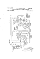
- Figure 1 is the circuit of the electronic integrator
- Figure 2 is a circuit diagram of a controller
- Figure 4 is another circuit, modified as compared with those illustrated in Figures 2 and 3.
- FIG. l of the accompanying drawings illustrates the integrating circuit according to the present invention.
- the voltage to be integrated is applied across the resistor A and charges the capacitor C in series with the resistor R.
- the capacitor voltage is transformed, by means of the triode V, into a current and a voltage proportional to that current is fed back through a magnetic amplifier B to the resistance capacitance circuit comprising the resistor R and the capacitor C.
- the magnetic amplifier provides an output voltage which is applied to the resistor D.
- the resistor D is serially connected between the resistor R and capacitor C.
- the voltage across resistor D is equal and opposite to the voltage across the capacitor C so that the instantaneous voltage across the capacitor C is balanced out.
- the charge on the capacitor C does not affect the current flow through the resistor R produced by the input voltage across the resistor A.
- the magnetic amplifier B has the great advantage that the insulation between its input and output can be made as high as that of any transformer and, since very little power is required to produce the compensation for the back voltage, the dimensions of the reactor may be very small.
- This insulation resistance may be of the order of thousands of megohms so that its effect with respect to the unavoidable discharge caused by the leakage resistance of the capacitor C is negligible.
- triode V can be replaced by other amplifying means, having the required characteristics, for instance transistors, as long as the input current required by such amplifying means is small as compared to the maximum discharge current of the condenser permitted for the particular integration.
- FIG. 2 of the drawings there is illustrated a controller in which a potential proportional the measured value of the controlled variable is applied to input terminals 1.
- the resulting current which is also proportional to the measured value, flows through a series circuit comprising a'resistor 2 and a measured value meter 3.
- a rectifier 4 is connected to the alternating circuit supply mains at terminals 5 and 6. Alternating current supply connections from terminals 5 and 6 extend to other points in the drawings which are designated AC. However, these additional connections have been omitted from the drawing for simplicity of illustration.
- the connection to the rectifier 4 passes through one pole of a six-pole three-position switch 45. The three positions are designated (a)--AUTOMATIC, (h)-HAND and (s)- SERVICE.
- the purpose of the HAND and SERVICE positions is described in detail below.
- the switch 45 is assumed to be in its AUTOMATIC position.
- the rectifier 4 supplies direct current to a DC. bus designated and
- a voltage regulator or stabilizing tube 7 is connected to the DC. bus through a resistor 8.
- the regulated supply serves as a source of screen voltage for pentodes 16 and 4t), later to be described.
- the regulated supply is also connected to a series circuit comprising an adjustably fixed resistor 9, a fixed resistor 19, and a potentiometer 11.
- the voltage drop across part of the potentiometer 11 is subtracted from the voltage across the input resistor 2.
- a potentiometer 12 and resistors 13 and 2b are included in a further circuit which is connected to the input resistor 2.
- the potentiometer 11 is adjusted to provide a potential with respect to the negative bus 11a which is equal and opposite to the potential across the input resistor 2 when as a current corresponding to the u! desired measured value for the controlled variable flows through the input
- the difference between the voltages across resistors 2 and 11 multiplied by a factor dependent on the position of the contact 14 of potentiometer 12 is applied to the control grid 15 of a pentode 16 to control its output.
- the screen 17 of pentode 16 is connected to the stabilising tube 7.
- the pentode 16 is supplied with anode potential from a rectifier 18 and its anode current passes through resistors 19 and 20 and returns via biasing resistors 21 and 22 to the cathode of pentode 16.
- the current in resistance 19 is therefore proportional to the deviation of the controlled value as represented by the voltage on the input resistor 2 minus the desired value potential adjusted on the potentiometer 11 and multiplied by the proportional band factor set on the contact 14.
- the loss of energy required for these mathematical operations is compensated by the amplification of the pentode 16.
- Regulated screen potential from the voltage regulator tube 7 passes through a resistor 23 to the output resistor 19 of pentode 16.
- This current through resistor 23 balances out the current flow through resistor 19 which is attributable to the normal space current through pentode 16 when the measured variable is at the desired value.
- the voltage across the output resistor 19 will vary in magnitude and polarity in accordance with deviations of the measured value of the controlled variable from its desired value as established on the potentiometer 11.
- the potential across the output resistor 19 charges an integrating capacitor 24 through a variable resistor 25 of high resistance through intermediate circuitry, later to be described.
- the charge on the integrating capacitor 24 is proportional to the time integral of the deviation from desired value which appears as the second term of the differential equation D, above.
- the time constant of the resistance-capacitance integrating circuit 25,24 can be varied by adjustment of the resistor 25.
- the intermediate circuitry includes two separate circuits, namely a limiter circuit and a feedback circuit.
- the limiter circuit comprises a full-wave rectifier 26 supplied from an alternating current supply, the output of rectifier 26 being filtered by an electrolytic capacitor 27.
- the filtered direct current output of rectifier 26 flows through three serially connected potentiometers 28, 29 and 30.
- the potentiometer 29 has a movable contact 31 which is connected through a halfwave rectifier 33 to the junction between resistors 19 and 20.
- the potentiometer has a movable contact 32 which is connected through another half-wave rectifier 34 to the junction between resistors 19 and 21).
- the feedback circuit comprises a potentiometer 35 connected in series with a resistor 36.
- the amount of voltage across potentiometer 35 which is introduced into the resistance-capacitance circuit 25,24 may be varied by adjustment of the movable potentiometer contact 37.
- the potentiometer 35 and resistor 36 are supplied with controlled rectified alternating current through a full-waverectifier, capacitor bridge circuit 38.
- the bridge circuit 38 is supplied with current from the output winding of a saturable reactor 39.
- the bridge circuit 38 and saturable reactor 39 operate in the same manner as the magnetic amplifier B of Fig. 1, constituting a feedback link of high insulation resistance between the integrating capacitor 24 and the output of the controller.
- the integrating capacitor 24 is connected in the control grid circuit of a pentode 40 in series with a potentiometer 41 and the resistor 26.
- the potentiometer 41 includes a movable contact 42 which is connected through a differentiating capacitor 43 to the output resistor 19 of pentode 16.
- the voltage drop across the potentiometer is a function of the time rate of change of the potential across output resistor 19 and represents the third term of the diiferential equation D, above.
- An output meter 44 is connected in the anode circuit of pentode 40.
- a full-wave rectifier 46 which is energized from the alternating current supply.
- This hand control circuit includes a calibrated variable resistor 47 which is shunted by the series combination of a fixed resistor 48 and an adjustably fixed resistor 49. The resistors 47, 48 and 49 are connected through a common adjustably fixed resistor 50 and switch 45 in its HAND position to the output meter 44.
- the movable contact 14 of potentiometer 12 is connected to the control grid 15 of pentode 16 through a series resistor 51.
- a fixed resistor 52 is substituted for the variable resistor 25, pentode 16 and output resistor 19 in the resistancecapacitance integrating circuit.
- a fixed resistor 53 is serially included in the resistance-capacitance circuit 25,24 being connected to the movable contact of the potentiometer 28 of the limiter circuit.
- a fixed resistor 54 is connected in series with the control grid of pentode 40.
- Another fixed resistor 55 connected in series with the cathode of pentode 40 serves as a biasing resistor.
- a resistor 56 is connected in series with the output meter 44 in the HAND position of switch 45.
- a resistor 57 is connected in series with the output meter 44 only in the SERVICE position of switch 45.
- the output circuit of the controller appears at terminals 58.
- the terminals 58 are adapted for connection to a controlling device which responds to changes in the anode current of the pentode 40.
- the output current from terminals 28 controls the degree of opening of a valve which regulates the supply of steam to a steam-heated vessel (not shown).
- the actual temperature of the vessel is measured by a thermocouple (not shown) connected to the input terminals 1 of the regulator.
- the desired temperature is set on the potentiometer 11. Any deviation of the actual temperature from the desired temperature will produce a corrective change in the output current at terminals 58. This deviation is hereinafter referred to as the error.
- the voltage which is built up across resistance 19 is an error voltage which is proportional to the error and a current that is a function of any change of that error voltage which flows through the resistances 19, 25, 35, 36, 53, 28 and 29 and the integrating capacitor 24 back to the resistance 19.
- the resistance of variable resistor 25 is very much larger than any of the others and the shunting effect of the latter therefore can be neglected.
- the voltage on the integrating capacitor 24 controls the output of the pentode 40 but the capacitor discharges itself across the resistances 19 and 25. The greater this volt-age the greater is the discharge current which expresses itself by an off-set of the controlled value necessary to maintain a voltage appropriate to the error on the integrating capacitor 24.
- the output current from the pentode 40 flows through the saturable reactor 39 and produces a current through the feedback circuit resistors 35 and 36 causing a voltage drop which is a function of the output current and is in opposition to the voltage on the integrating capacitor 24. Since the output current in turn is a function of the voltage on the integrating capacitor it is thereby possible to compensatefully for such a voltage and this makes it possible to increase the operative grid voltage to a reasonable value without affecting the accuracy of the controller.
- the limiter circuit fed by the rectifier 26 serves as integral action limitation. During the starting-up of a plant a very largeerror may occur for some time and this may cause the integrating circuit fully to charge the condenser 24 resulting in a much larger over-swing than would be obtained if the charge on the integrating capacitor 24 could be limited.
- An appropriate setting of the proportional band helps but the method used in general heretofore to avoid this over-swing is to use proportional plus derivative actions. If this mode of operation does not lead to a proportional band which is sufficiently narrow to restrict off-sets due to load changes, integral action is introduced, for instance first proportional plus derivative actions and subsequently proportional plus integral actions.
- the present controller Works differently. In the circuit associated with the potentiometers 29, 30 the voltage on the condenser 24 is opposed by a part of the voltage on the potentiometers 29 and 30. If for instance a current tries to flow from the integrating capacitor 24 in a clockwise direction, then the rectifier 34 would oppose its flow through the potentiometer 30. On the other hand, the current cannot flow through the rectifier 33 because it is opposed by the voltage on the potentiometer 29 up to a certain value which depends on the setting of contact 31. Beyond that value current from integrating capacitor 24 can discharge through the rectifier 33 and therefore its voltage is limited according to the setting of the contact 31. Rectifier 34 operates in the other direction. After the start of the plant the limitation is removed to enable the controller to work even beyond the points set temporarily (for integral action limitation.
- the six-pole switch 45 has three positions, AUTOMATIC, HAND and SERVICE designated a. h. s, respectively.
- AUTOMATIC position the controller is clearly automatic.
- HAND position the regulating unit is controlled directly by the hand control which is constituted by the variable resistor 47.
- the power for this control is obtained from the rectifier 46.
- This hand control is calibrated linearly in terms of the position of the regulating unit and has the same scale as the output meter 44.
- the index of the hand control variable resistor 47 should be set to agree with the pointer of the output meter 44.
- the position of the controlled device or steam valve under hand control will then be exactly the same as it was under auto control.
- the position of the controlled device may be altered by the hand control to any desired position.
- the current produced by the saturable reactor 39 flows through the resistors 35 and 36 of the feedback circuit and produces a voltage which, in the HAND operating position of the switch 45, is connected through the series resistance 52 through the integrating capacitor 24.
- the integral time resistance 25 is disconnected.
- the current through the saturable reactor therefore charges the integrating capacitor 24 to the voltage across the feedback circuit resistors 35 and 36 which is the value required to give a controller output similar to the current flowing through the energizing windings of the reactor from the hand control.
- the integral part of the controller therefore follows a. function of the output to the regulating unit as adjusted by the hand control and is independent of any measured and desired value.
- the actual output from the controller pentode 40 in this state which passes through the load resistance 56 is the sum of the simulated integral element value plus the proportiontal element and the derivative element value which latter are dependent on the error signal which is the difference between the measured and the desired value.
- the integrating capacitor 24 will always have the correct charge on it for the particular output that is passing through the controlled device under the hand control, and the controller output meter should be lined up either by altering the desired value or the position of the hand control. When these are in agreement the measured and desired values will be equal and no sudden shift in conditions will occur when the controller is switched to automatic operation.
- the SERVICE position of the switch 45 cuts out the automatic controller output and switches the meter 44 in series with the controlled device connected to the tenninals 58. Except for the rectifier 46, the mains transformer (not shown in the drawing), the hand control potentiometer 47 and the meter 44, all the rest of the controller is inoperative and the chassis containing the two pentodes, the measuring circuit and the desired value circuit may be removed, also the case containing the adjustments for the proportional band, integral and derivative time constants. This chassis may be taken out of the controller orreplaced by another chassis without upsetting the operation of the plant.
- the accuracy of the controller depends apart from the measured value, on the stability obtained by means of the voltage regulator tube 7 and on the zero stability of the voltage produced by the two opposing currents across the resistance 19. This stability is very high since there is a large amount of feed-back when a wide proportional band is used and naturally the sensitivity is very great when the proportional band is smalL.
- the device for compensating for the voltage on integrating capacitor 24 keeps the overall accuracy of the controller high.
- Pentode 16 (type 6AM6) has a continuous rating of 10 milliamps but this value is only reached in the extreme case of maximum error in one direction. If there is no error or only a small error as is usual with an automatic controller, the current passed by this valve is only 5 milliamps and it is therefore 50% under-run.
- the pentode 40 passing the controller output (type 6CH6) has a continuous rating 0f 40 milliamps whereas its current ranges between 3 and 15 milliamps. This valve too is therefore substantially under-run.
- the total heat dissipation of this controller is of the order of 25 watts, a large part of which is dissipated without entering the measuring and regulating compartment.
- The'controller described may, with suitably valued components control flow and pressure for which the integral action time is 1 minute and the derivative action time is 6 sees, the proportional band being 0200%. By altering the appropriate values the time constants and the value of the proportional band can be changed according to other requirements.
- FIG 3 of the drawings there is illustrated a controller incorporating a tube-type feed back amplifier in place of the saturable reactor 39 to compensate for the charge voltage on the integrating capacitor 24.
- the automanual switch has been eliminated and no transfer circuit has been shown.
- the whole of the desired value, measured value and proportional band is carried out as previously described; the resistance 20 in the circuit shown in Figure 2 has been renumbered 60, as this resistance is now only used for the feed-back on the proportional band and not to develop the voltage for the output valve in addition as before.
- the standing current from the proportional pentode 16 is opposed as before from the voltage across the regulator tube 7 through the resistance 23.
- This two-way proportional current flows through the output circuit 53, the arruneter 44 and resistances 79, 62, 61 19 and and passes the proportional element directly on to the controlled device. Therefore output valve 71 only has to handle the integral and derivative currents.
- the potentiometer 61 and resistor 62 take the current from which draws power from rectifier 63 and load resistance 65 feedback triode 64. The drop across these resistances due to this current is the voltage which compensates for the charge on integrating capacitor 24.
- These two resistances 61 and 62 are similar to the resistances 35 and 36 in the previous controller. In this case the feedback adjustment is carried out on the potentiometer 61 instead of the potentiometer 35 of Fig. 2.
- the rest of charging circuit for the integrating capacitor 24 is exactly similar, the charging current passing through the integral adjustment resistor 25, the resistor 53, the potential divider 28 and the limiter circuit.
- the rectifier supply 4 which in the previous case only supplied the pentode 16, has also to supply the output pentode 71. Due to the large voltage drop across resistance 19, due to proportional error, it is not possible to energize the screen of the output pentode 71 from the regulated supply using the regulator tube 7. Therefore, another circuit is used where load and screen resistors 68 and 69, respectively, are associated with the output pentode 71.
- the screen voltage is stabilised by an additional voltage regulator tube 70 so that its voltage relative to cathode only varies by the drop across the output 58, the ammeter 44 and the resistances 79 and 55.
- the voltage drop across the resistance 69 will always be the dilference between the voltage on rectifier 18 and stabilising tube 70 and will remain constant irrespective of the anode current, while the drop across the resistance 68 will fluctuate with the anode current.
- the current from pentode 71 which passes through the output 58 will be the sum of both the screen and anode currents.
- the feedback tube 64 has been shown as a triode as there is no simple way of obtaining a screen supply.
- Resistance 66 acts as a negative feedback resistance which tends to stabilise the output and make it possible to replace the valve without much adjustment.
- the grid voltage for the feedback triode 64 is developed across the resistance 79 which is connected in series to the output, the voltage across which will depend upon the total output.
- the output of the feedback triode 64 is therefore proportional to the voltage on the integrating capacitor 24 when there is no error; with an error, as before the proportional element can be taken care of in the calibration of the integral time and the transient eifect of the derivative will cause a small error.
- the output current from the triode 64 passes through the potentiometer 61 and resistor 62, the values of which are so arranged that the voltage drop across them due to this current compensates the voltage on the condenser 24.
- the fixed bias of the limiter circuit which is developed across otentiometers 28 and 29 and resistor 30 is so adjusted that with no voltage drop across the fixed resistor 19, the algebraic sum of the voltage drops across resistor 62, potentiometer 61, integrating capacitor 24, potentiometer 29 and potentiometer 28 at all times is equal to zero, regardless of the charge on the integrating capacitor 24 which is compensated by the voltage drop across potentiometer 61 and resistor 62.
- the voltage drops in the limiter circuit of Fig. 3 are in the opposite direction to those in Fig. 2. Accordingly, the polarities of the limiting rectifiers 33 and 34 are reversed with respect to those in Fig. 2.
- the proportional current also passes through potentiometer 61 and resistor 62.
- the eifect of the proportional current in potentiometer 61 and resistor 62 is the same as its effect in resistor 19 and can be allowed for during 10 calibration. It also alters the anode voltage of the feed back triode 64. However, this effect is a linear effect and can be compensated during calibration.
- the controller of Fig. 3 using a tubetype feedback is very similar in its performance to the performance of the controller circuit with a saturable reactor as previously described.
- the modified three term controller illustrated in Figure 4 is basically the same as that illustrated in Figure 2 and similar items bear like reference numbers but in this circuit the condenser 24 is charged in one direction only, which is important, since it makes it possible to use electrolytic condensers with much smaller dimensions than have the paper insulated types. Furthermore the condenser voltage and the reactor voltage are equal and opposite and there is therefore no need for the extra biasing voltage used in the previous layout.
- the signal coming to a con troller is not unidirectional but for instance in the case of a temperature measurement by means of a Wheatstone bridge the error signal is positive or negative.
- the setting of the desired value is carried out on the bridge by shifting its balance point and the stabiliser 7 is no longer used for balancing the measured voltage, but only for the stabilisation of the circuit.
- An electronic controller having a direct current continuous input; means to give a direct current error signal; means amplifying the error signal; a first and second resistance in series with the amplifying means, the voltage across said second resistance being a proportional error voltage; a series-connected third resistance and first condenser in parallel to said first resistance, the first con denser being connected to the junction of the first and second resistances and the voltage across said first condenser being an integral error voltage; a series-connected second condenser and fourth resistance connected in parallel to said third resistance, the second condenser being connected to the first and third resistances, the fourth resistance being connected to the junction of the third resistance and first condenser and the voltage across the said fourth resistance being a differential error voltage; a first connection from the end of the second resistance remote from'the first resistance; a second connection from the junction of the fourth resistance and second condenser, the voltage across said first and second connections being a summation of the proportional, integral and differential error voltages; amplifying means to measure and transform the voltage
- An electronic controller for a controlled system comprising means providing an error current proportional to the error in the controlled system, a resistance fed by the error current to provide a proportional action voltage, a second resistance, a series connected resistance and condenser integrating the voltage produced by said error current in said second resistance to give integral action voltage, means connecting said proportional action voltage and integral action voltage in summation to give a tWo term control voltage, amplifying means measuring and transforming said two term control Voltage to give a controller output, and high insulation feedback means passing a function of said controller output to said condenser to substantially compensate the voltage thereof.
- An electric controller comprising an input circuit adapted to receive a direct current signal which varies with positive and negative going excursions to either side of zero, the variations being in accordance with variations in a quantitatively measured factor controlled by said controller, a first resistor in said input circuit, the potential across said first resistor varying in accordance with said variations, a series connected combination of a second resistor and a capacitor connected to said first resistor so that the potential across said capacitor varies in accordance with the time integral of the magnitude of said signal, amplifier means having its input connected for response to the potential across said capacitor, high resistance coupling means connecting the output of said amplifier means to the circuit of said second resistor and capacitor, said amplifier means introducing a potential into said last-named circuit through said coupling means which is equal and opposite to the potential across said capacitor, and an output circuit connected to the output of said amplifier means, said output circuit being adapted for connection to control means for varying said controlled factor in accordance with said time integral.
- An electric controller comprising an input circuit adapted to receive a direct current signal which varies in accordance with variations in a quantitatively measured factor controlled by said controller, a first resistor in said input circuit, the potential across said first resistor varying in accordance with said variations, a series connected combination of a second resistor and a capacitor connected to said first resistor so that the potential across said capacitor varies in accordance with the time integral of the magnitude of said signal, amplifier means having its input connected for response to the potential across said capacitor, high resistance coupling means connecting the output of said amplifier means to the circuit of said second resistor and capacitor, said amplifier means introducing a potential into said last-named circuit through said coupling means which is equal and opposite to the potential across said capacitor, and an output circuit connected to the output of said amplifier means, said output circuit being adapted for connection to control means for varying said controlled factor in accordance with said time integral.
- An electric controller further comprising a resistor-capacitor differentiating circuit connected to said input circuit, circuit means connecting said differentiating circuit to said output circuit for introducing a potential in said output circuit which is proportional to the time rate of change of said signal, and means for adjusting the relative intensities of said time integral and time rate of change efiiects in said output circuit.
- An electric controller further comprising a regulated adjustable source of direct current the constant potential of which maybe varied manually, circuit means for comparing said adjustable constant potential with the potential across said first resistor, the algebraic difference between said adjustable potential and the potential across first resistor constituting an error signal the magnitude and direction of which varies in accordance with deviations of said controlled factor from a predetermined desired magnitude, said second resistor and capacitor being connected to derive a potential which varies in accordance with the time integral of the magnitude of said error signal.
- An electric controller according to claim 4, further comprising circuit means interconnecting said controller input circuit and said controller output circuit, said last-named circuit means introducing into said output circuit a potential Which is proportional to the potential across said first resistor.
- An electric controller further comprising a resistor-capacitor differentiating circuit connected to said input circuit, circuit means connecting said differentiating circuit to said output circuit for introducing a potential in said output circuit which is proportional to the time rate of change of said signal, and means for adjusting the relative intensities of said time integral and time rate of change effects in said output circuit.
- said high resistance couplingmeans comprises a magnetic amplifier interposing high resistance insulation between said output of said amplifier means and said circuit of said second resistor and capacitor.
Landscapes
- Physics & Mathematics (AREA)
- Engineering & Computer Science (AREA)
- Mathematical Physics (AREA)
- General Physics & Mathematics (AREA)
- Theoretical Computer Science (AREA)
- Software Systems (AREA)
- Computer Hardware Design (AREA)
- Automation & Control Theory (AREA)
- Control Of Voltage And Current In General (AREA)
Applications Claiming Priority (1)
| Application Number | Priority Date | Filing Date | Title |
|---|---|---|---|
| GB29990/54A GB826341A (en) | 1954-10-18 | 1954-10-18 | Improvements in or relating to integrators and automatic controllers |
Publications (1)
| Publication Number | Publication Date |
|---|---|
| US2957980A true US2957980A (en) | 1960-10-25 |
Family
ID=10300469
Family Applications (1)
| Application Number | Title | Priority Date | Filing Date |
|---|---|---|---|
| US538498A Expired - Lifetime US2957980A (en) | 1954-10-18 | 1955-10-04 | Electronic integrators and automatic controllers |
Country Status (3)
| Country | Link |
|---|---|
| US (1) | US2957980A (enExample) |
| FR (1) | FR1137654A (enExample) |
| NL (1) | NL201258A (enExample) |
Cited By (2)
| Publication number | Priority date | Publication date | Assignee | Title |
|---|---|---|---|---|
| US3134027A (en) * | 1960-11-15 | 1964-05-19 | Gen Precision Inc | Precision integrator |
| US3652942A (en) * | 1971-01-18 | 1972-03-28 | Lummus Co | Feedback control system |
Citations (14)
| Publication number | Priority date | Publication date | Assignee | Title |
|---|---|---|---|---|
| US2140350A (en) * | 1936-10-16 | 1938-12-13 | Westinghouse Electric & Mfg Co | Control apparatus |
| US2251973A (en) * | 1935-03-21 | 1941-08-12 | Int Standard Electric Corp | Circuits for integrating and differentiating electric variations |
| US2462456A (en) * | 1945-04-14 | 1949-02-22 | Rca Corp | Antihunt servomotor control system |
| US2463553A (en) * | 1944-04-05 | 1949-03-08 | Cons Eng Corp | Integrating system |
| US2506770A (en) * | 1946-01-30 | 1950-05-09 | Rca Corp | Wave shape correction circuit |
| US2511564A (en) * | 1946-12-26 | 1950-06-13 | Magnetic Analysis Corp | Distortion analysis |
| US2566832A (en) * | 1946-12-18 | 1951-09-04 | Rca Corp | Synchronizing circuit |
| US2584954A (en) * | 1948-05-08 | 1952-02-05 | Leeds & Northrup Co | Self-balancing electrical system and method |
| US2608678A (en) * | 1948-03-15 | 1952-08-26 | Evershed Vignoles Ltd | Electrical controlling apparatus |
| US2622231A (en) * | 1948-09-28 | 1952-12-16 | Gen Precision Lab Inc | Integrator |
| US2637820A (en) * | 1950-03-03 | 1953-05-05 | Collins Radio Co | Current integrator |
| US2687474A (en) * | 1952-02-14 | 1954-08-24 | Glenn L Martin Co | Integrator |
| US2708258A (en) * | 1949-12-29 | 1955-05-10 | Rca Corp | Anti-hunt circuit for electric motor follow-up systems |
| US2728041A (en) * | 1949-07-06 | 1955-12-20 | Evershed Vignoles Ltd | Proportional band setting device for electric motor condition controlling apparatus |
-
0
- NL NL201258D patent/NL201258A/xx unknown
-
1955
- 1955-10-04 US US538498A patent/US2957980A/en not_active Expired - Lifetime
- 1955-10-17 FR FR1137654D patent/FR1137654A/fr not_active Expired
Patent Citations (14)
| Publication number | Priority date | Publication date | Assignee | Title |
|---|---|---|---|---|
| US2251973A (en) * | 1935-03-21 | 1941-08-12 | Int Standard Electric Corp | Circuits for integrating and differentiating electric variations |
| US2140350A (en) * | 1936-10-16 | 1938-12-13 | Westinghouse Electric & Mfg Co | Control apparatus |
| US2463553A (en) * | 1944-04-05 | 1949-03-08 | Cons Eng Corp | Integrating system |
| US2462456A (en) * | 1945-04-14 | 1949-02-22 | Rca Corp | Antihunt servomotor control system |
| US2506770A (en) * | 1946-01-30 | 1950-05-09 | Rca Corp | Wave shape correction circuit |
| US2566832A (en) * | 1946-12-18 | 1951-09-04 | Rca Corp | Synchronizing circuit |
| US2511564A (en) * | 1946-12-26 | 1950-06-13 | Magnetic Analysis Corp | Distortion analysis |
| US2608678A (en) * | 1948-03-15 | 1952-08-26 | Evershed Vignoles Ltd | Electrical controlling apparatus |
| US2584954A (en) * | 1948-05-08 | 1952-02-05 | Leeds & Northrup Co | Self-balancing electrical system and method |
| US2622231A (en) * | 1948-09-28 | 1952-12-16 | Gen Precision Lab Inc | Integrator |
| US2728041A (en) * | 1949-07-06 | 1955-12-20 | Evershed Vignoles Ltd | Proportional band setting device for electric motor condition controlling apparatus |
| US2708258A (en) * | 1949-12-29 | 1955-05-10 | Rca Corp | Anti-hunt circuit for electric motor follow-up systems |
| US2637820A (en) * | 1950-03-03 | 1953-05-05 | Collins Radio Co | Current integrator |
| US2687474A (en) * | 1952-02-14 | 1954-08-24 | Glenn L Martin Co | Integrator |
Cited By (2)
| Publication number | Priority date | Publication date | Assignee | Title |
|---|---|---|---|---|
| US3134027A (en) * | 1960-11-15 | 1964-05-19 | Gen Precision Inc | Precision integrator |
| US3652942A (en) * | 1971-01-18 | 1972-03-28 | Lummus Co | Feedback control system |
Also Published As
| Publication number | Publication date |
|---|---|
| NL201258A (enExample) | |
| FR1137654A (fr) | 1957-06-03 |
Similar Documents
| Publication | Publication Date | Title |
|---|---|---|
| US2190743A (en) | Measuring system | |
| US2692358A (en) | Electric motor positioning system | |
| US3042848A (en) | Voltage regulator | |
| US2511219A (en) | Voltage regulator | |
| US2866151A (en) | Voltage regulator with non-linear networks in control circuit | |
| US2957980A (en) | Electronic integrators and automatic controllers | |
| US3303412A (en) | Current regulated power supply with compensating means for extraneous shunting current paths across the load | |
| US2232212A (en) | Apparatus for amplifying direct current voltages and currents | |
| US2414242A (en) | Voltage regulation | |
| US2701858A (en) | Voltage regulating systems | |
| US2840777A (en) | Direct current power source | |
| US2595034A (en) | Antihunting measuring and controlling apparatus | |
| US2690535A (en) | Voltage regulator | |
| US2780734A (en) | Voltage regulating system | |
| US2550122A (en) | Control system | |
| US2885627A (en) | Voltage regulating device | |
| US2407140A (en) | Electric microgauge system | |
| US2455143A (en) | Cathode controlled electronic voltage regulator circuit | |
| US2966625A (en) | Multiple-feedback-path regulating systems for generators | |
| US2536245A (en) | Measuring and controlling apparatus | |
| US2949575A (en) | Temperature compensated bolometer bias supply | |
| US2629854A (en) | Electronic voltage regulator | |
| US3058066A (en) | Electrical circuit having direct current voltage output proportional to a variable direct current | |
| US2435573A (en) | Voltage regulation | |
| US2825023A (en) | Load compensated voltage regulated power supplies |