US2957504A - Seal arrangement for nozzle and fitting - Google Patents
Seal arrangement for nozzle and fitting Download PDFInfo
- Publication number
- US2957504A US2957504A US79713759A US2957504A US 2957504 A US2957504 A US 2957504A US 79713759 A US79713759 A US 79713759A US 2957504 A US2957504 A US 2957504A
- Authority
- US
- United States
- Prior art keywords
- nozzle
- adapter
- fitting
- seal
- ring
- Prior art date
- Legal status (The legal status is an assumption and is not a legal conclusion. Google has not performed a legal analysis and makes no representation as to the accuracy of the status listed.)
- Expired - Lifetime
Links
- 239000012530 fluid Substances 0.000 description 16
- 239000000446 fuel Substances 0.000 description 12
- 238000007789 sealing Methods 0.000 description 4
- 230000008878 coupling Effects 0.000 description 3
- 238000010168 coupling process Methods 0.000 description 3
- 238000005859 coupling reaction Methods 0.000 description 3
- XEEYBQQBJWHFJM-UHFFFAOYSA-N Iron Chemical compound [Fe] XEEYBQQBJWHFJM-UHFFFAOYSA-N 0.000 description 2
- 230000004048 modification Effects 0.000 description 2
- 238000012986 modification Methods 0.000 description 2
- 241000157282 Aesculus Species 0.000 description 1
- 229910001369 Brass Inorganic materials 0.000 description 1
- 230000009471 action Effects 0.000 description 1
- 239000010951 brass Substances 0.000 description 1
- 239000002828 fuel tank Substances 0.000 description 1
- 235000010181 horse chestnut Nutrition 0.000 description 1
- 229910052742 iron Inorganic materials 0.000 description 1
- 230000003137 locomotive effect Effects 0.000 description 1
- 230000002093 peripheral effect Effects 0.000 description 1
- 230000004044 response Effects 0.000 description 1
- 230000000284 resting effect Effects 0.000 description 1
Images
Classifications
-
- F—MECHANICAL ENGINEERING; LIGHTING; HEATING; WEAPONS; BLASTING
- F16—ENGINEERING ELEMENTS AND UNITS; GENERAL MEASURES FOR PRODUCING AND MAINTAINING EFFECTIVE FUNCTIONING OF MACHINES OR INSTALLATIONS; THERMAL INSULATION IN GENERAL
- F16L—PIPES; JOINTS OR FITTINGS FOR PIPES; SUPPORTS FOR PIPES, CABLES OR PROTECTIVE TUBING; MEANS FOR THERMAL INSULATION IN GENERAL
- F16L37/00—Couplings of the quick-acting type
- F16L37/28—Couplings of the quick-acting type with fluid cut-off means
- F16L37/30—Couplings of the quick-acting type with fluid cut-off means with fluid cut-off means in each of two pipe-end fittings
- F16L37/36—Couplings of the quick-acting type with fluid cut-off means with fluid cut-off means in each of two pipe-end fittings with two lift valves being actuated to initiate the flow through the coupling after the two coupling parts are locked against withdrawal
-
- B—PERFORMING OPERATIONS; TRANSPORTING
- B64—AIRCRAFT; AVIATION; COSMONAUTICS
- B64D—EQUIPMENT FOR FITTING IN OR TO AIRCRAFT; FLIGHT SUITS; PARACHUTES; ARRANGEMENT OR MOUNTING OF POWER PLANTS OR PROPULSION TRANSMISSIONS IN AIRCRAFT
- B64D37/00—Arrangements in connection with fuel supply for power plant
- B64D37/005—Accessories not provided for in the groups B64D37/02 - B64D37/28
-
- F—MECHANICAL ENGINEERING; LIGHTING; HEATING; WEAPONS; BLASTING
- F16—ENGINEERING ELEMENTS AND UNITS; GENERAL MEASURES FOR PRODUCING AND MAINTAINING EFFECTIVE FUNCTIONING OF MACHINES OR INSTALLATIONS; THERMAL INSULATION IN GENERAL
- F16L—PIPES; JOINTS OR FITTINGS FOR PIPES; SUPPORTS FOR PIPES, CABLES OR PROTECTIVE TUBING; MEANS FOR THERMAL INSULATION IN GENERAL
- F16L37/00—Couplings of the quick-acting type
- F16L37/24—Couplings of the quick-acting type in which the connection is made by inserting one member axially into the other and rotating it to a limited extent, e.g. with bayonet-action
- F16L37/244—Couplings of the quick-acting type in which the connection is made by inserting one member axially into the other and rotating it to a limited extent, e.g. with bayonet-action the coupling being co-axial with the pipe
- F16L37/248—Bayonet-type couplings
-
- Y—GENERAL TAGGING OF NEW TECHNOLOGICAL DEVELOPMENTS; GENERAL TAGGING OF CROSS-SECTIONAL TECHNOLOGIES SPANNING OVER SEVERAL SECTIONS OF THE IPC; TECHNICAL SUBJECTS COVERED BY FORMER USPC CROSS-REFERENCE ART COLLECTIONS [XRACs] AND DIGESTS
- Y10—TECHNICAL SUBJECTS COVERED BY FORMER USPC
- Y10T—TECHNICAL SUBJECTS COVERED BY FORMER US CLASSIFICATION
- Y10T137/00—Fluid handling
- Y10T137/598—With repair, tapping, assembly, or disassembly means
- Y10T137/612—Tapping a pipe, keg, or apertured tank under pressure
- Y10T137/613—With valved closure or bung
- Y10T137/6137—Longitudinal movement of valve
-
- Y—GENERAL TAGGING OF NEW TECHNOLOGICAL DEVELOPMENTS; GENERAL TAGGING OF CROSS-SECTIONAL TECHNOLOGIES SPANNING OVER SEVERAL SECTIONS OF THE IPC; TECHNICAL SUBJECTS COVERED BY FORMER USPC CROSS-REFERENCE ART COLLECTIONS [XRACs] AND DIGESTS
- Y10—TECHNICAL SUBJECTS COVERED BY FORMER USPC
- Y10T—TECHNICAL SUBJECTS COVERED BY FORMER US CLASSIFICATION
- Y10T137/00—Fluid handling
- Y10T137/8593—Systems
- Y10T137/87917—Flow path with serial valves and/or closures
- Y10T137/87925—Separable flow path section, valve or closure in each
- Y10T137/87941—Each valve and/or closure operated by coupling motion
- Y10T137/87949—Linear motion of flow path sections operates both
Definitions
- a fuel filling adapter embodying the basic design with which the present invention is concerned is illustrated and described in United States Patent No. 2,753,884, and a fluid nozzle adapted for use with such an adapter is illustrated and described in United States Patent Nos
- the adapter illustrated in the patent identified above and which in that case is a fuel filling adapter, together with the nozzle similarly identified forms a satisfactory way for effectively coupling conduits for filling containers and the like.
- the sealing between the adapter fitting and the nozzle to prevent leakage of the fluid is also quite effective.
- a still further object of the present invention is the provision of additional sealing means in the adapter beyond what is presently provided to assist in supporting the nozzle against deflection and also to improve the seal between the nozzle and the adapter.
- a still further object of this invention is the provision of a simple arrangement for maintaining an absolutely fluid-tight seal against leakage. between vva pair of telescopically interfitted members while at the same time permitting free relief of any suction developed between 2,957,504 lcg Patented Oct. 25, 1960 the members and to accomplish the foregoing in a. very simple and inexpensive manner.
- Figure 1 is a perspective view showing one instance wherein a fuel filling adapter according to the present invention is employed
- FIG 2 is a vertical section through the fuel filling adapter as indicated by line 2-2 on Figure 1 showing a filling nozzle attached to the adapter;
- Figure 3- is a fragmentary view taken at enlarged scale showing the auxiliary seal of the adapter member and the seal for the vacuum relief arrangement according to the present invention.
- Figure 1 illustrates an aircraft 10 having w ing tanks adapted for being filled through a fuel filling adapter 12 which may be mounted on the underside of the wing.
- This adapter could, of course, be mounted on top of the wing orin any other tank or container which it is desired to fill with fuel, and accordingly, the showing of Figure 1 is intended merely as an illustration of one circumstance in which the adapter could be used.
- the fuel filling adapter 12 has a flow passage 14 therethrough for the passage of fuel and that at the lower end of the adapter there is a ring 16 having a tapered seat 18 against which a valve member 20 seats under the action of a spring 22.
- a rubber-like ring 24 on the valve member provides a resilient fluid-tight engagement of the valve member with the tapered valve seat.
- Beneath ring 16 is a cylindrical member 26 which extends downwardly and forms the portion of the filling adapter fitting which telescopically receives the end of the fuel filling nozzle 28.
- the lower end of the cylindrical member 26 and the upper end of nozzle 28 comprises cooperating element of a bayonet latch generally indicated at 30 so that the nozzle can be latched to the adapter preparatory to the flow of fluid therethrough,
- a cap 32 is attached to the lower end of the fuel filling adapter and serves as a closure therefor.
- the nozzle 28 has a projecting cylindrical portion 34 that slidably fits within cylindrical member 26 of the adapter. At its upper end cylindrical portion 34 of the nozzle has an 0 ring 36 that seats against a radial flange on the inside of member 26 to form a seal between the nozzle and the adapter fitting.
- the upper end of cylindrical portion 34 of the nozzle is outwardly tapered and forms a seat for the nozzle valve member 38 which also has a rubber-like ring 40 to provide for a resilient fluid-tight seating of the valve member against its seat.
- the nozzle is coupled to the adapter, and the valve member 38 of the nozzle is pushed upwardly which in turn pushes the valve member 20 of the adapter upwardly and opens the passage for the supply of fuel in one direction or the other through the nozzle and adapter.
- valve member of the nozzle is closed and this permits the adapter valve member to close and thereafter the nozzle is uncoupled from the adapter and the cap 32 is replaced on the adapter.
- additional support is provided for the nozzle in the form of annular O ring 42 which is received within a groove 44 extending about the inside of cylindrical member 26 between the lower end thereof and the aforementioned radial flange against which 0 ring 40 of the nozzle seats.
- This added, O ring supports the nozzle against lateral movement and assists in guiding it into the proper place within the adapter, and provides added protection against leakagefrom between the nozzle and adapter.
- a suction is drawn between the valve members of the nozzle and adapter and this suction can develop quite high forces up'to 100 pounds or can 'cause'the valve member of the nozzle to be drawn open and fuel spilled therefrom.
- the advantages of the added support and seal of the additional ring 42 is gained without the drawbacks referred to above by providing in the cylindrical member 26 between 0 ring 40 and the valve member of the adapter an'annular V groove 46 which forms a Wedge shaped seat for an O ring 48 and with there being drilled holes 50 extending from the bottom of groove 46 to the atmosphere.
- Drilled holes 50 may be fairly small, say, about 0.050 inch in diameter and there may be up to 6 of the holes provided.
- the groove 46 may be up to about A of an inch at its widest part and O ring 48 will be somewhat smaller, say, from A; to of an inch in diameter.
- 0 ring 48 is of such a size that it fits closely within groove 46 engaging the tapering sides of the groove under at least slight pressure so that no pressure can be expelled from the inside of the adapter outwardly through holes 50.
- 0 ring 48 due to the extreme flexibility of 0 ring 48, even a slight suction inside the adapter member is suflicient for the air entering through holes 50 to deform the O ring slightly and thus relieve the suction by a supply of atmosphere.
- a fitting for receiving a nozzle having a cylindrical discharge end to establish a fluid tight flow passage comprising; a cylindrical member adapted for fitting closely about the cylindrical end of the nozzle, a radial flange in the member to engage the end of the nozzle, spaced resilient seal means between the end of the nozzle and the flange and between the inside of the member and the peripheral portion of the nozzle, and means in the cylindrical member between said seal means operable to admit air into the cylindrical member in response to suction created therein while preventing fluid from leaking from the cylindrical member due to pressure established therein.
- a fitting for receiving a nozzle having a cylindrical discharge and to establish a fluid tight flow passage comprising; a cylindrical member adapted for fitting closely about the cylindrical end of the nozzle, a radial flange in the member to engage the end of the nozzle, a rubber-like seal between the end of the nozzle and the flange, a second rubber-like seal between the inside of the member and the outside of the nozzle spaced from the said first seal, port means communicating the inside of the member between the seals with the atmosphere, and means associated with the port means operable to permit air to enter said member through said port means While preventing fiuid from passing from said member.
- a fitting for receiving a nozzle having a cylindrical discharge end to establish a fluid tight flow passage comprising; a cylindrical member adapted for fitting closely about the cylindrical end of the nozzle, a radial flange in the member to engage the end of the nozzle, spaced annular rubber-like seals between the nozzle part, a rubber-like seal ring on the extreme end of the end part, an adapter fitting pertaining to a receiver to receive fluid from the nozzle, said adapter fitting comprising a portion having a cylnidrical recess to receive the said end part of the nozzle comprising a flange to abut the seal ring on th eend of the nozzle, a rubber-like seal carried on the inside of said cylindrical portion to engage the periphery of the said end part of the nozzle at a region spaced from the said seal ring, means for latching the nozzle to the adapter fitting, and means in the adapter fitting between the seal ring and seal operable to relieve suction therebetween while preventing
- a nozzle having a cylindrical end part, a rubber-like seal ring on the extreme end of the end part, an adapter fitting, said adapter fitting comprising a portion having a cylindrical recess to receive the said end part of the nozzle comprising a flange to abut the seal ring on the end of the nozzle, a rubber-like sealv carried on the inside of said cylindrical portion to engage the periphery of the said end part of the nozzle at a region spaced from the said seal ring, means for latching the nozzle to the adapter fitting, a valve member in the nozzle movable outwardly thereof to open the flow passage through the nozzle, a valve member in the adapter fittin gmovable inwardly thereof to open the flow passage therethrough, said valve members being substantially in face to face relation when the nozzle is attached to the adapter fitting whereby opening of the nozzle valve member will open the adapter fitting valve member, a groove in the inside of the adapter fitting between the said seal and seal ring, ports
- a nozzle having a cylindrical end part, a rubber-like seal ring on the extreme end of the end part, an adapter fitting pertaining to a receiver to receive fluid from the nozzle, said adapter fitting comprising a portion having a cylindrical recess to receive the said end part of the nozzle comprising a flange to abut the seal ring on the end of the nozzle, a rubber-like seal carried on the inside of said cylindrical portion to engage the periphery of the said end part of the nozzle at a region spaced from the said seal ring, means for latching the nozzle to the adapter fitting, said nozzle tapering outwardly at the end and said adapter fitting tapering inwardly, valve members having rubber-like peripheries in the outer ends of the nozzle and adapter fitting which are substantially in face to face engagement when the nozzle and fitting are coupled together so outward movement of the nozzle valve member will cause inward movement of the valve member of the adapter fitting to permit fluid flow therethrough, a V groove in the inside of
- a nozzle having a cylindrical end part, a rubber-like seal ring on the extreme end of the end part, an adapter fitting pertaining to a receiver to receive fluid from the nozzle, said adapter fitting comprising a portion having a cylindrical recess to receive the said end part of the nozzle comprising a flange to abut the seal ring on the end of the nozzle, a rubber-like seal carried on the inside of said cylindrical portion to engage the periphery of the said end part of the nozzle at a region spaced from the said seal ring, means for latching the nozzle to the adapter fitting, said nozzle tapering outwardly at the end and said adapter fitting tapering inwardly, valve members having rubber-like peripheries in the outer ends of the nozzle and adapter fitting which are substantially in face to face engagement when the nozzle and fitting are coupled together so outward movement of the nozzle valve member will cause inward movement of the valve member of the adapter fitting to permit fluid flow therethrough, a V groove in the inside of
Landscapes
- Engineering & Computer Science (AREA)
- General Engineering & Computer Science (AREA)
- Mechanical Engineering (AREA)
- Aviation & Aerospace Engineering (AREA)
- Loading And Unloading Of Fuel Tanks Or Ships (AREA)
Description
Oct. 25, 1960 L. A. BOTKIN SEAL ARRANGEMENT FOR NOZZLE AND FITTING Filed March 4, 1959 na/a INVENTOR. LAWRENCE A. BOT/(Ml ATTOENEH Unite States Patent SEAL ARRANGEMENT FORNOZZLE AND FITTING" r Lawrence A. Botkin, Dayton, Ohiofassignor to Buckeye Iron & Brass Works, Dayton, Ohio, a corporation of This inventionrelates to improvements in fluid flow adapter fittings, particularly to adapters for attaching nozzles or couplings to relatively large storage and supply tanks such as the fuel tanks of aircraft, diesel locomotives, tank trucks, power boats and the like, or for coupling together fluid supply lines or for making connections in hydrant systems at the ends of the branch conduits thereof.
A fuel filling adapter embodying the basic design with which the present invention is concerned, is illustrated and described in United States Patent No. 2,753,884, and a fluid nozzle adapted for use with such an adapter is illustrated and described in United States Patent Nos The adapter illustrated in the patent identified above and which in that case is a fuel filling adapter, together with the nozzle similarly identified forms a satisfactory way for effectively coupling conduits for filling containers and the like. The sealing between the adapter fitting and the nozzle to prevent leakage of the fluid is also quite effective. However, it has been found that with the effective seals necessary to prevent leakage, when the adapter is closed, and the nozzle is closed, it sometimes becomes quite difficult toremove the nozzle from the adapter due to the suction created when the nozzle is withdrawn from the adapter. Since these nozzles and adapters sometimes reach substantial sizes, up to two and three inches in effective diameter, the suction tending to hold the nozzle on the adapter may even approach 100 pounds in extreme cases. This introduces the possibility, when the nozzle is separated from the adapter, of the valve member of one or the other of the nozzle and adapter becoming damaged, or the valve of the nozzle being drawn outwardly and with a possible loss of fluid from the nozzle which, if the fluid is corrosive or flammable, might be dangerous.
With the foregoing in mind, it is a particular object of this invention to provide an adapter fitting of the nature referred to in which adequate sealing between a filling nozzle attached to the adapter and the adapter is maintained but without causing any difficulty in connection with dis-engaging the nozzle from the adapter.
Heretofore, the sealing between nozzles and adapters of the nature described has been at the end of the nozzle and this has introduced the possibility of the nozzle tilting in the adapter and causing leakage or undue wear about the engaging portions of the nozzle and adapter. With this in mind, a still further object of the present invention is the provision of additional sealing means in the adapter beyond what is presently provided to assist in supporting the nozzle against deflection and also to improve the seal between the nozzle and the adapter.
A still further object of this invention is the provision of a simple arrangement for maintaining an absolutely fluid-tight seal against leakage. between vva pair of telescopically interfitted members while at the same time permitting free relief of any suction developed between 2,957,504 lcg Patented Oct. 25, 1960 the members and to accomplish the foregoing in a. very simple and inexpensive manner.
These and other objects and advantages will become more apparent upon reference to the drawings in which:
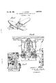
Figure 1 is a perspective view showing one instance wherein a fuel filling adapter according to the present invention is employed;
Figure 2 is a vertical section through the fuel filling adapter as indicated by line 2-2 on Figure 1 showing a filling nozzle attached to the adapter; and
Figure 3- is a fragmentary view taken at enlarged scale showing the auxiliary seal of the adapter member and the seal for the vacuum relief arrangement according to the present invention.
Referring to the drawings somewhat more in detail, Figure 1 illustrates an aircraft 10 having w ing tanks adapted for being filled through a fuel filling adapter 12 which may be mounted on the underside of the wing. This adapter could, of course, be mounted on top of the wing orin any other tank or container which it is desired to fill with fuel, and accordingly, the showing of Figure 1 is intended merely as an illustration of one circumstance in which the adapter could be used.
Turning now to Figure 2, it will be seen that the fuel filling adapter 12 has a flow passage 14 therethrough for the passage of fuel and that at the lower end of the adapter there is a ring 16 having a tapered seat 18 against which a valve member 20 seats under the action of a spring 22. A rubber-like ring 24 on the valve member provides a resilient fluid-tight engagement of the valve member with the tapered valve seat.
Beneath ring 16 is a cylindrical member 26 which extends downwardly and forms the portion of the filling adapter fitting which telescopically receives the end of the fuel filling nozzle 28. The lower end of the cylindrical member 26 and the upper end of nozzle 28 comprises cooperating element of a bayonet latch generally indicated at 30 so that the nozzle can be latched to the adapter preparatory to the flow of fluid therethrough, When the nozzle is detached a cap 32 is attached to the lower end of the fuel filling adapter and serves as a closure therefor.
The nozzle 28 has a projecting cylindrical portion 34 that slidably fits within cylindrical member 26 of the adapter. At its upper end cylindrical portion 34 of the nozzle has an 0 ring 36 that seats against a radial flange on the inside of member 26 to form a seal between the nozzle and the adapter fitting. The upper end of cylindrical portion 34 of the nozzle is outwardly tapered and forms a seat for the nozzle valve member 38 which also has a rubber-like ring 40 to provide for a resilient fluid-tight seating of the valve member against its seat.
In operation, the nozzle is coupled to the adapter, and the valve member 38 of the nozzle is pushed upwardly which in turn pushes the valve member 20 of the adapter upwardly and opens the passage for the supply of fuel in one direction or the other through the nozzle and adapter.
After the operation is completed the valve member of the nozzle is closed and this permits the adapter valve member to close and thereafter the nozzle is uncoupled from the adapter and the cap 32 is replaced on the adapter.
According to the present invention additional support is provided for the nozzle in the form of annular O ring 42 which is received within a groove 44 extending about the inside of cylindrical member 26 between the lower end thereof and the aforementioned radial flange against which 0 ring 40 of the nozzle seats. This added, O ring supports the nozzle against lateral movement and assists in guiding it into the proper place within the adapter, and provides added protection against leakagefrom between the nozzle and adapter. However, when the nozzle is to be separated from the adapter a suction is drawn between the valve members of the nozzle and adapter and this suction can develop quite high forces up'to 100 pounds or can 'cause'the valve member of the nozzle to be drawn open and fuel spilled therefrom.
According to this invention the advantages of the added support and seal of the additional ring 42 is gained without the drawbacks referred to above by providing in the cylindrical member 26 between 0 ring 40 and the valve member of the adapter an'annular V groove 46 which forms a Wedge shaped seat for an O ring 48 and with there being drilled holes 50 extending from the bottom of groove 46 to the atmosphere.
Drilled holes 50 may be fairly small, say, about 0.050 inch in diameter and there may be up to 6 of the holes provided. The groove 46 may be up to about A of an inch at its widest part and O ring 48 will be somewhat smaller, say, from A; to of an inch in diameter. 0 ring 48 is of such a size that it fits closely within groove 46 engaging the tapering sides of the groove under at least slight pressure so that no pressure can be expelled from the inside of the adapter outwardly through holes 50. However, due to the extreme flexibility of 0 ring 48, even a slight suction inside the adapter member is suflicient for the air entering through holes 50 to deform the O ring slightly and thus relieve the suction by a supply of atmosphere. The net result is that no amount of pressure escaping past the end of the nozzle of O ring 40 will cause any leakage, whereas, when the nozzle is uncoupled from the adapter, there is no resistance to removing of the nozzle from the adapter and no tendency for the valve member of the nozzle to be drown open by suction between the nozzle and the adapter. Such a condition of suction is substantially entirely relieved through holes 50 and past 0 ring 48.
It will be understood that this invention is susceptible to modification in order to adapt it to ditterent usages and conditions; and, accordingly, it is desired to comprehend such modifications within this invention as may fall within the scope of the appended claims.
I claim:
1. A fitting for receiving a nozzle having a cylindrical discharge end to establish a fluid tight flow passage comprising; a cylindrical member adapted for fitting closely about the cylindrical end of the nozzle, a radial flange in the member to engage the end of the nozzle, spaced resilient seal means between the end of the nozzle and the flange and between the inside of the member and the peripheral portion of the nozzle, and means in the cylindrical member between said seal means operable to admit air into the cylindrical member in response to suction created therein while preventing fluid from leaking from the cylindrical member due to pressure established therein.
2. A fitting for receiving a nozzle having a cylindrical discharge and to establish a fluid tight flow passage comprising; a cylindrical member adapted for fitting closely about the cylindrical end of the nozzle, a radial flange in the member to engage the end of the nozzle, a rubber-like seal between the end of the nozzle and the flange, a second rubber-like seal between the inside of the member and the outside of the nozzle spaced from the said first seal, port means communicating the inside of the member between the seals with the atmosphere, and means associated with the port means operable to permit air to enter said member through said port means While preventing fiuid from passing from said member.
3. A fitting for receiving a nozzle having a cylindrical discharge end to establish a fluid tight flow passage comprising; a cylindrical member adapted for fitting closely about the cylindrical end of the nozzle, a radial flange in the member to engage the end of the nozzle, spaced annular rubber-like seals between the nozzle part, a rubber-like seal ring on the extreme end of the end part, an adapter fitting pertaining to a receiver to receive fluid from the nozzle, said adapter fitting comprising a portion having a cylnidrical recess to receive the said end part of the nozzle comprising a flange to abut the seal ring on th eend of the nozzle, a rubber-like seal carried on the inside of said cylindrical portion to engage the periphery of the said end part of the nozzle at a region spaced from the said seal ring, means for latching the nozzle to the adapter fitting, and means in the adapter fitting between the seal ring and seal operable to relieve suction therebetween while preventing escape of pressure.
5. In combination; a nozzle having a cylindrical end part, a rubber-like seal ring on the extreme end of the end part, an adapter fitting, said adapter fitting comprising a portion having a cylindrical recess to receive the said end part of the nozzle comprising a flange to abut the seal ring on the end of the nozzle, a rubber-like sealv carried on the inside of said cylindrical portion to engage the periphery of the said end part of the nozzle at a region spaced from the said seal ring, means for latching the nozzle to the adapter fitting, a valve member in the nozzle movable outwardly thereof to open the flow passage through the nozzle, a valve member in the adapter fittin gmovable inwardly thereof to open the flow passage therethrough, said valve members being substantially in face to face relation when the nozzle is attached to the adapter fitting whereby opening of the nozzle valve member will open the adapter fitting valve member, a groove in the inside of the adapter fitting between the said seal and seal ring, ports through the wall of the adapter fitting in the bottom of the groove, and a rubber-like ring resting in the groove to seal the ports against outflow therethrough while permitting inflow therethrough.
6. In combination; a nozzle having a cylindrical end part, a rubber-like seal ring on the extreme end of the end part, an adapter fitting pertaining to a receiver to receive fluid from the nozzle, said adapter fitting comprising a portion having a cylindrical recess to receive the said end part of the nozzle comprising a flange to abut the seal ring on the end of the nozzle, a rubber-like seal carried on the inside of said cylindrical portion to engage the periphery of the said end part of the nozzle at a region spaced from the said seal ring, means for latching the nozzle to the adapter fitting, said nozzle tapering outwardly at the end and said adapter fitting tapering inwardly, valve members having rubber-like peripheries in the outer ends of the nozzle and adapter fitting which are substantially in face to face engagement when the nozzle and fitting are coupled together so outward movement of the nozzle valve member will cause inward movement of the valve member of the adapter fitting to permit fluid flow therethrough, a V groove in the inside of the adapter member between the seal and seal ring, a rubber-like O ring in the groove engaging the sides thereof, and port means leading from the bottom of the groove to the atmosphere.
7. In combination; a nozzle having a cylindrical end part, a rubber-like seal ring on the extreme end of the end part, an adapter fitting pertaining to a receiver to receive fluid from the nozzle, said adapter fitting comprising a portion having a cylindrical recess to receive the said end part of the nozzle comprising a flange to abut the seal ring on the end of the nozzle, a rubber-like seal carried on the inside of said cylindrical portion to engage the periphery of the said end part of the nozzle at a region spaced from the said seal ring, means for latching the nozzle to the adapter fitting, said nozzle tapering outwardly at the end and said adapter fitting tapering inwardly, valve members having rubber-like peripheries in the outer ends of the nozzle and adapter fitting which are substantially in face to face engagement when the nozzle and fitting are coupled together so outward movement of the nozzle valve member will cause inward movement of the valve member of the adapter fitting to permit fluid flow therethrough, a V groove in the inside of the adapter member between the seal and seal ring, a rubber-like O ring in the groove engaging the sides thereof, and port means leading from the bottom of the groove to the atmosphere, said 0 ring being in pressure engagement with the surface of said groove.
References Cited in the file of this patent UNITED STATES PATENTS 2,629,395 Krone et a1. Feb. 24, 1953 2,630,822 Davies Mar. 10, 1953 2,713,989 Bryant July 26, 1955 2,753,884 Lindsay July 10, 1956
Priority Applications (1)
| Application Number | Priority Date | Filing Date | Title |
|---|---|---|---|
| US79713759 US2957504A (en) | 1959-03-04 | 1959-03-04 | Seal arrangement for nozzle and fitting |
Applications Claiming Priority (1)
| Application Number | Priority Date | Filing Date | Title |
|---|---|---|---|
| US79713759 US2957504A (en) | 1959-03-04 | 1959-03-04 | Seal arrangement for nozzle and fitting |
Publications (1)
| Publication Number | Publication Date |
|---|---|
| US2957504A true US2957504A (en) | 1960-10-25 |
Family
ID=25170012
Family Applications (1)
| Application Number | Title | Priority Date | Filing Date |
|---|---|---|---|
| US79713759 Expired - Lifetime US2957504A (en) | 1959-03-04 | 1959-03-04 | Seal arrangement for nozzle and fitting |
Country Status (1)
| Country | Link |
|---|---|
| US (1) | US2957504A (en) |
Cited By (4)
| Publication number | Priority date | Publication date | Assignee | Title |
|---|---|---|---|---|
| US3148704A (en) * | 1962-09-26 | 1964-09-15 | Buckeye Iron & Brass Works | Combination or branch valve |
| US3330529A (en) * | 1964-02-24 | 1967-07-11 | Atlas Copco Ab | Fluid conduit coupling |
| US4512369A (en) * | 1982-02-26 | 1985-04-23 | Niigata Engineering Co., Ltd. | Emergency disconnector for fluid loading and unloading lines |
| US20230175632A1 (en) * | 2021-12-03 | 2023-06-08 | Hosan Tech Co., Ltd. | Coupler and clean connection device having the same |
Citations (4)
| Publication number | Priority date | Publication date | Assignee | Title |
|---|---|---|---|---|
| US2629395A (en) * | 1951-03-21 | 1953-02-24 | Wheaton Brass Works | Hydrant for aircraft refueling |
| US2630822A (en) * | 1947-05-29 | 1953-03-10 | Parker Appliance Co | Valve means for controlling the filling and draining of tanks |
| US2713989A (en) * | 1948-01-22 | 1955-07-26 | Grove Valve & Regulator Co | Valve construction |
| US2753884A (en) * | 1953-01-26 | 1956-07-10 | Buckeye Iron & Brass Works | Fuel filling adapter |
-
1959
- 1959-03-04 US US79713759 patent/US2957504A/en not_active Expired - Lifetime
Patent Citations (4)
| Publication number | Priority date | Publication date | Assignee | Title |
|---|---|---|---|---|
| US2630822A (en) * | 1947-05-29 | 1953-03-10 | Parker Appliance Co | Valve means for controlling the filling and draining of tanks |
| US2713989A (en) * | 1948-01-22 | 1955-07-26 | Grove Valve & Regulator Co | Valve construction |
| US2629395A (en) * | 1951-03-21 | 1953-02-24 | Wheaton Brass Works | Hydrant for aircraft refueling |
| US2753884A (en) * | 1953-01-26 | 1956-07-10 | Buckeye Iron & Brass Works | Fuel filling adapter |
Cited By (5)
| Publication number | Priority date | Publication date | Assignee | Title |
|---|---|---|---|---|
| US3148704A (en) * | 1962-09-26 | 1964-09-15 | Buckeye Iron & Brass Works | Combination or branch valve |
| US3330529A (en) * | 1964-02-24 | 1967-07-11 | Atlas Copco Ab | Fluid conduit coupling |
| US4512369A (en) * | 1982-02-26 | 1985-04-23 | Niigata Engineering Co., Ltd. | Emergency disconnector for fluid loading and unloading lines |
| US20230175632A1 (en) * | 2021-12-03 | 2023-06-08 | Hosan Tech Co., Ltd. | Coupler and clean connection device having the same |
| US12435824B2 (en) * | 2021-12-03 | 2025-10-07 | Hosan Tech Co., Ltd. | Coupler and clean connection device having the same |
Similar Documents
| Publication | Publication Date | Title |
|---|---|---|
| US2401674A (en) | Fluid transfer device | |
| US3125135A (en) | Filling device with detachable flow coupling means | |
| US3589397A (en) | Antirefill valve | |
| US4098293A (en) | Fluid pressure coupling arrangement | |
| US2737401A (en) | Fuel servicing nozzle | |
| US3171448A (en) | Fluid connection | |
| US2349137A (en) | Safety valve for tanks | |
| KR910002704A (en) | Binary Syrup System Units and Valves | |
| US3055405A (en) | Automatic tank-filling systems | |
| US3542063A (en) | Filler valve | |
| US2630822A (en) | Valve means for controlling the filling and draining of tanks | |
| US2957504A (en) | Seal arrangement for nozzle and fitting | |
| US2753884A (en) | Fuel filling adapter | |
| US3800979A (en) | Lpg valve assembly | |
| US2836207A (en) | Aviation fueling hydrant valve | |
| US3387738A (en) | Closure seal | |
| US2522406A (en) | Combination valve | |
| US2593712A (en) | Filling fitting | |
| US2420315A (en) | Booster pump shut-off casing for pump removal | |
| US3144056A (en) | Apparatus for loading and unloading a fuel tank | |
| GB1315973A (en) | Valves for containers | |
| US1661202A (en) | Tank-car siphon valve | |
| US4248362A (en) | Dispenser closure | |
| US3156271A (en) | Fueling device | |
| US1933085A (en) | Valve |