US2956830A - Record changer - Google Patents
Record changer Download PDFInfo
- Publication number
- US2956830A US2956830A US404191A US40419154A US2956830A US 2956830 A US2956830 A US 2956830A US 404191 A US404191 A US 404191A US 40419154 A US40419154 A US 40419154A US 2956830 A US2956830 A US 2956830A
- Authority
- US
- United States
- Prior art keywords
- record
- turntable
- records
- speed
- needle
- Prior art date
- Legal status (The legal status is an assumption and is not a legal conclusion. Google has not performed a legal analysis and makes no representation as to the accuracy of the status listed.)
- Expired - Lifetime
Links
Images


Classifications
-
- G—PHYSICS
- G11—INFORMATION STORAGE
- G11B—INFORMATION STORAGE BASED ON RELATIVE MOVEMENT BETWEEN RECORD CARRIER AND TRANSDUCER
- G11B19/00—Driving, starting, stopping record carriers not specifically of filamentary or web form, or of supports therefor; Control thereof; Control of operating function ; Driving both disc and head
- G11B19/20—Driving; Starting; Stopping; Control thereof
- G11B19/26—Speed-changing arrangements; Reversing arrangements; Drive-transfer means therefor
-
- G—PHYSICS
- G11—INFORMATION STORAGE
- G11B—INFORMATION STORAGE BASED ON RELATIVE MOVEMENT BETWEEN RECORD CARRIER AND TRANSDUCER
- G11B17/00—Guiding record carriers not specifically of filamentary or web form, or of supports therefor
- G11B17/02—Details
- G11B17/022—Positioning or locking of single discs
- G11B17/028—Positioning or locking of single discs of discs rotating during transducing operation
- G11B17/0281—Positioning or locking of single discs of discs rotating during transducing operation by an adapter enabling the centre-pin to receive carriers with large centre hole
-
- G—PHYSICS
- G11—INFORMATION STORAGE
- G11B—INFORMATION STORAGE BASED ON RELATIVE MOVEMENT BETWEEN RECORD CARRIER AND TRANSDUCER
- G11B17/00—Guiding record carriers not specifically of filamentary or web form, or of supports therefor
- G11B17/08—Guiding record carriers not specifically of filamentary or web form, or of supports therefor from consecutive-access magazine of disc records
- G11B17/12—Guiding record carriers not specifically of filamentary or web form, or of supports therefor from consecutive-access magazine of disc records with axial transfer to the turntable from a stack with a vertical axis
- G11B17/16—Guiding record carriers not specifically of filamentary or web form, or of supports therefor from consecutive-access magazine of disc records with axial transfer to the turntable from a stack with a vertical axis by mechanism in stationary centre post, e.g. with stepped post, using fingers on post
- G11B17/162—Guiding record carriers not specifically of filamentary or web form, or of supports therefor from consecutive-access magazine of disc records with axial transfer to the turntable from a stack with a vertical axis by mechanism in stationary centre post, e.g. with stepped post, using fingers on post with means for detecting the diameter of the record
- G11B17/165—Guiding record carriers not specifically of filamentary or web form, or of supports therefor from consecutive-access magazine of disc records with axial transfer to the turntable from a stack with a vertical axis by mechanism in stationary centre post, e.g. with stepped post, using fingers on post with means for detecting the diameter of the record with mechanical detecting means
Definitions
- the present invention relates to automatic phonograph apparatus, and, more particularly, to a new and improved automatic record changer for phonograph apparatus.
- the present state of the phonograph art there are a number of dilferent types of phonograph records on the market of different sizes and having different playing speeds.
- certain types of records have been discontinued so that it may be generally stated that a playing speed of 33 /3 r.p.m. 10 inch and 12 inch records are presently available with standard centering apertures; at a playing speed of 45 r.p.m.
- 7 inch records are available, with either an enlarged centering aperture in which case inserts may be used to adapt these records for a standard centering spindle or a standard centering aperture is provided directly; and at a playing speed of 78 r.p.m., l and 12 inch records are generally available with standard centering apertures and 7 inch childrens records with standard centering apertures are also available.
- the phonograph art has also become sufficiently standardized so that it may be stated that the conventional'transducer arrangements incorporate two sizes of needles, a one mil needle being used to play 33 /3 r.p.m. records and 45 r.p.m. recods and a 3 mil needle being used for 78 r.p.m. records.
- Another object of the present invention resides in the provision of an automatic record changer wherein a group of 33 /3 r.p.m. 10 inch and 12 inch records and 45 r.p.m. 7 inch records may be played intermixed and a group of 78 r.p.m. 7 inch, 10 inch and 12 inch records may be played intermixed while requiring the operator to select only the desired size of needle and initiate playing of either intermixed group.
- a further object of the invention resides in the provision of an automatic record changer wherein the turntable speed is automatically adjusted in accordance with the size of the selected phonograph needle so that the operator is informed by the pitch of the reproduced sound when the size of the selected needle is not the same as the groove size of the selected record and damage to needles and records is avoided.
- Another object of the present invention resides in the provision of a new and improved automatic record changer wherein the turntable speed is automatically adjusted to 45 r.p.m. upon the selection of a slip-on spindle suitable for playing large centering aperture 45 r.p.m. records.
- a further object of the present invention resides in the provision of a new and improved automatic record changer wherein the turntable speed is automatically adjusted to 45 r.p.m. when a large centering aperture adapter member is positioned on the turntable.
- a still further object of the present invention resides in the provision of a new and improved automatic record changer wherein the duration of each changing cycle is the same regardless of the playing speed of the record and the speed of the turntable is automatically adjusted to the playing speed of the top record on the turntable at substantially the end of each record changing cycle.
- the trip mechanism of most of the conventional record changers on the market today is of the velocity trip type wherein the increased velocity of the tone arm when it encounters the run-out groove of the record is employed to actuate the trip mechanism.
- These trip mechanisms place such a large frictional load on the tone arm that they will not function properly with low needle pressure tone arm arrangements. This is particularly true in the case of extended play 45 r.p.m. records in which the playing portion of the record is increased to a maximum and the run-out groove lasts for only a single revolution of the record so that the velocity trip mechanism must function with only a very brief increase in the velocity of the tone arm.
- Another object of the present invention resides inthe provision of a new and improved velocity trip. mechanism for an automatic record changer in which the frietional loading of the trip mechanism is extremely small so that positive tripping action is provided for very brief increases in tone arm velocity and with very low needle pressures.
- the tone arm mounting is so arranged that the tone arm is not released until the end of the record changing cycle even though the tone arm is positioned on the record a substantial period before the record changing cycle ends.
- the tone arm is held over the lead-in groove of the uppermost record until the record changing cycle is completed and is prevented from moving inwardly as the stylus engages the record groove so that the stylus is twisted and the needle may become damaged thereby.
- the spring tension which is built up when the tone arm is held and the stylus is twisted in many instances causes the tone arm to jump several grooves of the record when the tone arm is released at the end of the record changing cycle.
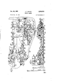
- Fig. l is a top plan view of an automatic record changer embodying the features of the present invention.
- Fig. 2 is a bottom view of Fig. l;
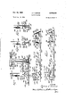
- FIG. 3 is a top view of the record changer of Fig. 1 on a somewhat larger scale and shown with the turntable, tone arm and cover plate removed;
- Fig. 4 is a perspective view of the record changer of Fig. 1 shown with the turntable removed and the base plate of the changer partially exposed;
- Fig. 5 is a fragmentary plan view of the record changer of Fig. 1, partly in section, and showing the cycling slide in substantially the mid-point of the changing cycle;
- Fig. 6 is a fragmentary side elevational view of the portion of the record changer shown in Fig. 5;
- Fig. 7 is a fragmentary side elevational view taken along the line 77 of Fig. 5;
- Fig. 8 is a fragmentary side elevational view similar to Fig. 7 and showing the tone arm indexing cam in the ten inch position;
- Fig. 9 is a fragmentary side elevational view similar to Fig. 7 and showing the tone arm indexing cam in the twelve inch position;
- Fig. 10 is a fragmentary side elevational view similar to Fig. 6 and showing the driving mechanism in the 45 r.p.m. position;
- Fig. 11 is a side elevational view similar to Fig. 10 and showing the drive mechanism in the 78 r.p.m. position;
- Fig. 12 is a fragmentary side elevational view of the record changer of Fig. 3 taken along the line 12-.12 thereof and with the turntable added;
- Fig. 13 is a fragmentary side elevational view similar the record changer of to Fig. 12 and showing the size indexing finger withdrawn;
- Fig. 14 is a sectional view taken along the line 14-14 of Fig. 12 and showing the relative positions of the parts just after the record holddown arm is seated after the last record;
- Fig. 15 is a sectional view taken along the line 15-15 of Fig. 13 and showing the tone arm indexing cam in the last record shut-oft position;
- Fig. 15a is a fragmentary perspective view of the, shutoff spring used in the automatic shut-off mechanism shown in Fig. 13;
- Fig. 16 is a sectional view taken along the line 16-16 of Fig. 5;
- Fig. 16a is a sectional view on a larger scale of the turntable and drive wheel mounting arrangement shown in Fig. 16;
- Fig. 17 is a sectional side elevational view similar to Fig. 16 and showing the cycling slide in a different position;
- Fig. 18 is a sectional view taken along the line 18-18 of Fig. 16;
- Fig. 19 is a fragmentary plan view of a portion of the record changer of Fig. 1 showing the operation of the trip arm and the delay mechanism therefor;
- Fig. 19a is a fragmentary plan view on a somewhat larger scale of the delay trip mechanism shown in Fig. 19;
- Fig. 19b is a sectional view taken along the line 19b-19b of Fig. 19;
- Fig. 20 is a side elevational view taken along the line 20-20 of Fig. 19;
- Fig. 21 is a sectional side elevational view taken along the line 21-21 of Fig. 19;
- Fig. 22 is a sectional side elevational view similar to Fig. 20 and showing the tripping mechanism in a differ ent position;
- Fig. 23 is a fragmentary plan view of the record changer of Fig. 1 showing the details of the last record shut-01f mechanism and neutral positioning mechanism;
- Fig. 24 is a fragmentary plan view of a portion of Fig. 23 showing the shut-off mechanism in a different position;
- Fig. 25 is a fragmentary plan view of an alternative embodiment of the present invention wherein automatic speed change is provided in conjunction with a 45 r.p.m. slip-on spindle;
- Fig. 26 is a sectional side elevational view taken along the line 26-26 of Fig. 25;
- Fig. 27 is a sectional side elevational view taken along the line 27-27 of Fig. 26;
- Fig. 28 is a fragmentary plan view of afurther alternative embodiment of the present invention wherein automatic speed change is provided in conjunction with a 45 r.p.m. slip-on spindle receiving well;
- Fig. 29 is a sectional side elevational view taken along the line 29-29 of Fig. 28;
- Fig. 30 is a sectional side elevational view similar to Fig. 29 and showing a 45 r.p.m. slip-on spindle positioned within its receiving well;
- Fig. 31 is a fragmentary plan view of an alternative embodiment of the invention wherein facilities are provided for playing 16 /3 r.p.m. records;
- Fig. 32 is a sectional side elevational view taken along the line 32-32 of Fig. 31;
- Fig. 33 is a top plan view of an alternative embodiment of the invention wherein a modified turntable drive and automatic speed changing mechanism is provided;
- Fig. 34 is a fragmentary plan view of the embodiment shown in Fig. 33 on a somewhat larger scale;
- Fig. 35 is a sectional side elevational view taken along" the line 35-35 of Fig. 34;
- Fig. 36 is a sectional side elevational view taken along 'the line 36-36 of Fig. 34;
- Fig. 37 is a fragmentary plan viewof an alternative 6 embodiment of the invention wherein facilities for manual record playing are provided; 7
- Fig. 38 is a sectional side elevational view taken along the line 38-38 of Fig. 37;
- Fig. 39 is a fragmentary plan view of a portion of Fig. 37 and showing the manual control linkage in another position; i I
- Fig. 40 is, a sectional view taken along the line 40-40 of Fig. 39 and showing the tripmechanism in a different position;
- Fig. '41 is a fragmentary sectional side elevational view of an alternative embodiment of the invention, taken along the center line of the spindle and showing an arrangement for disengaging the turntable from the drive mechanism except during period when one or more records are positioned on the turntable;
- Fig. 42 is a fragmentary sectional plan view taken along the line 42--42 of Fig. 41;
- Fig. 43 is a fragmentary plan view of an alternative embodiment of the invention wherein facilities are provided for playing 78 r.p.m. microgroove records;
- Fig. 44 is a sectional view taken along the line 44-44 of Fig. 43;
- Fig. 45 is a somewhat diagrammatic side elevational view of an alternative 78 r.p.m. microgroove arrangement.
- Fig. 46 is a somewhat diagrammatic side elevational view of another alternative 78 r.p.m. microgroove arrangement.
- the record changer of the present invention is therein illustrated as comprising a base member, indicated generally at 50, which supports the component parts of the record changer including a rotatable turntable 51, a tone arm 52, and a record hold-down arm 53, the arm 53 being mounted on a supporting member 54 which latter member also houses a size indexing finger 55.
- a centering spindle 56 is also supported on the base plate 50 and carries a stack of records in non-playing position which may be individually released to the turntable 51 during successive record changing cycles as will be described in more detail hereinafter.
- the base plate 50 is enclosed by a cover member which includes the top plate 58 and sides 59, a raised portion including the side members 60, 61, 62 and 63, and the removable cover plate 64 being provided so that the components which are positioned on the base plate 50 are substantially completely enclosed.
- the cover plate 64 carries a tone arm rest post 65 on which the tone arm 52 is adapted to be positioned during non-playing intervals.
- the cover plate 64 is also provided with an opening 66 through which extends a depressible operable button 67, the button 67 comprising the sole operating control of the record changer.
- the tone arm 52 is provided with a head portion 68 within which is positioned a conventional two position cartridge (not shown) provided with a rotatable needle selecting arm 69 which projects from the front end of the tone arm 52 and may be adjusted manually to select needles of two different sizes, i.e., one mil and three mil needles, in accordance with the groove size of the records which are to be played.
- a needle selecting arm 69 is in the position shown in Fig. l a one mil needle, which is suitable for playing 33 /3 r.p.m. and 45 r.p.m. records is positioned to engage the grooves of a record on the turntable 51, whereas when the needle selecting arm 69 is in the posittion shown in Fig.
- a three mil needle which is suitable for playing 78 r.p.m. records is positioned to engage the grooves of a record on the turntable 51.
- suitable indicia are conventionally provided on the opposite sides of the needle selecting arm 69 so as to inform the operator which size of needle is positioned to engage the record.
- a vertically extending 78 r.p.m. speed indexing rod 70 is supported on the end of a bracket 71 which pr0jt$ through an opening 72 in the side member 62 and extends upwardly to apoint adjacent the needle selecting arm 69 when this arm is in the 78 r.p.m. needle selecting position.
- the record changer of the present invention is adapted to play seven inch 45 r.p.m. records and ten inch and 12 inch 33% r.p.m. records completely automatically and in intermixed sequence without any adaptation of the records themselves, other than the provision of suitable adaptors for the spindle 56.
- the "record changer is adapted to play seven inch, ten inch and twelve inch 78 r.p.m. records completely automatically and in intermixed sequence without any adaptation of the records themselves and without any modification or adjustment of the machine other than the normal adjustment of the needle selecting arm 69 to the 78 r.p.m. needle position.
- the turntable 51 starts to rotate and the bottommost record of the stack supported on the spindle 56 is dropped to the turntable 51 after which the tone arm 52 is moved to the correct position over the edge of the record and lowered into engagement with the lead-in groove of the record.
- a twelve inch 33 /3 r.p.m. record 75 (Fig. 1) is dropped to the turntable 51, as this record falls it strikes the size indexing arm 55 and moves it downwardly to the position shown in dotted lines at 76 in Fig. 12 with the result that the tone arm 52 is positioned in the run-in groove of the twelve inch record.
- the speed of the turntable 51 is automatically adjusted to 33 /3 r.p.m.
- the tone arm 52 is lifted otf of the record and moved outwardly beyond the edge of the record, after which the next record in the stack supported on the spindle 56 is dropped to the turntable 51.
- the tone arm 52 is controlled so that the hub 77 of the needle selecting arm 69 does not strike the 78 r.p.m. speed indexing rod 70 in the extreme outward position of the tone arm 52.
- the next record changing cycle is initiated and the tone arm 52 is removed from the path of the record in the manner described above and the next record is dropped to the turntable, the tone arm 52 again being controlled so that the rod 70 is not moved thereby.
- the size indexing arm 55 is not struck by this record and the tone arm 52 is controlled accordingly so that it is positioned in the run-in groove of the seven inch record 80.
- the speed of the turntable 51 is automatically adjusted to 45 r.p.m. so that the record is played at the correct playing speed.
- a group of these records of different sizes may be placed on the spindle 56 and the needle selecting arm 69 is adjusted to the 78 r.p.m. needle position shown in Fig. 4.
- the tone arm 52 is positioned on the rest 65 the needle selecting arm 69 is positioned adjacent to but not touching the upper end of the 78 r.p.m. speed indexing rod 70.
- the operate button 67 is depressed a record changing cycle is initiated and the first 78 r.p.m. record is dropped to the turntable 51. At substantially the mid-point of this record changing cycle, the tone arm 52 is moved outwardly beyond the rest position shown in Fig.
- the record changing mechanism is controlled so that the speed of the turntable 51 is adjusted to 78 r.p.m. at substantially the end of the record changing cycle with the result that when the tone arm 52 is positioned in the runin groove of the 78 r.p.m. record the turntable 51 is operating at the correct playing speed.
- the size indexing arm 55 functions in the manner described above to position the tone arm 52 in accordance with the size of the 78 r.p.m. records deposited on the turntable 51. Since the needle selecting arm 69 remains in the 78 r.p.m.
- the record changer of the present invention distinguishes between 78 r.p.m. records and microgroove records, i.e., 33 /3 r.p.m. and 45 r.p.m. records, on the basis of the size of the selected needle and further distinguishes between 33% r.p.m. records and 45 r.p.m. records on the basis of record size so that all records may be played completely automatically and without any separate speed adjustments on the part of the operator. It will also be noted that the record changer of the present invention is so constructed and arranged that the operator is immediately informed by the pitch of the reproduced sound if the wrong needle size has been selected for a given record.
- the control rod 70 is moved in the manner described above so as to control the record changing mechanism to shift the speed of the turntable 51 to 78 r.p.m. Accordingly, the microgroove record is played at approximately twice the normal playing speed thereof so that the operator is immediately informed by the abnormally high pitch of the reproduced sound that the wrong needle size has been selected and can change the needle to the correct size before the microgroove needle or record is damaged.
- the needle selecting arm 69 is in the 33% and 45 r.p.m.
- the speed of the turntable is automatically adjusted to either 33 /3 r.p.m. or 45 r.p.m., depending upon the size of the record, and the operator is immediately informed by the abnormally low pitch that the wrong needle size has been selected since the 78 r.p.m. record will be played at approximately one-half its normal playing speed.
- the needle selecting arm 69 can only be in one of two positions so that even if the operator is blind-folded he has a 50-50 chance of playing the records correctly by merely putting them on the spindle 56 and depressing the button 67.
- Turntable drive mechanism Considering now in more detail the manner in which the turntable 51 is driven, it will be recalled from the mechanism is provided which is driven at a speed of 16% r.p.m. for one revolution during which the record change is completed. With this arrangement the record changing cycle is of constant duration regardless of the playing speed of the records. While it is possible to slow down the turntable from a playing speed of 33 /5 r.p.m.
- a low inertia drive wheel indicated generally at 90, which is positioned concentrically with the spindle 56 and drives the turntable 51 in the playing direction through a suitable clutch mechanism while permitting the turntable 51 to coast freely when the drive wheel 90 is slowed down.
- the drive wheel 90 also drives the record changing mechanism and the speed of the drive Wheel 90 is reduced to 16 /3 r.p.m. during the record changing cycle after which the speed of the drive wheel 90 is changed to the playing speed of the new record deposited 'on the turntable 51, and drives the turntable 51 in the playing direction at this playing speed.
- a motor indicated generally at 91 (Fig. 2), which is positioned on a mounting bracket 92 which is resiliently Lmounted on the underside of the base plate 50 by means ,of the mounting screws 93, the shaft 94 of the motor 91 extending upwardly through an irregular opening 95a in the base plate 50.
- the upper end of the shaft 94 engages the largest diameter step 95 of a multi-step turret 96 which is rotatably mounted on one end of a bell crank lever 97.
- the bell crank lever 97 is pivotally supported from the base plate 50 on the post 98 secured thereto and a spring 99 is connected from one arm of the bell crank lever 97 to an intermediate point on a bracket 100 which is secured to the base plate 50 and extends into the open? ing 95a so that the bottom step 95 of the turret 96 is normally urged into engagement with the upper end of the drive shaft 94.
- An idler wheel 101 is rotatably mounted on a post 102 secured to one end of a lever 103 the other end of which is pivotally secured to one end of a bell crank lever indicated generally at 104.
- the bell crank lever 104 is provided with a hub portion 105 which is rotatably mounted on a post 106 secured to the base plate 50 and the arm 107 of the bell crank 104 is provided at the end thereof with an enlarged end portion 108 to which the lever 103 is pivotally secured.
- a spring 109 is connected from the free end of the lever 103 to a point on the bell crank lever 97 so that theidler wheel 101 is normally urged into engagement with one of the steps on the multi-step turret 96.
- the drive wheel 90 is provided with a bearing sleeve (Fig. 16) which is rotatably mounted on the spindle 56 and a hub plate 116 is secured to the bottom end of the sleeve 115 and terminates in the spokes 117, 118 and 119 which project radially outwardly from the hub plate 116 and support at the outer ends thereof a rim 120.
- the spindle 56 is supported within the opening 121 (Fig. 16a) in the base plate 50 by means of a threaded bushing 122 which is secured to the spindle 56 and is provided with a shoulder which cooperates with the nut 124 to clamp the spindle 56 securely to the base plate 50.
- a threaded bushing 122 which is secured to the spindle 56 and is provided with a shoulder which cooperates with the nut 124 to clamp the spindle 56 securely to the base plate 50.
- the idler wheel 101 is adapted to engage the inner edge of the rim 120 when the record changer is operating so that the drive wheel 90 is driven from the turret 96 through the idler wheel 101 at a speed determined by the particular step of the turret 96 with which the idler wheel 101 is in engagement.
- a rubber tired clutch wheel which is secured to the spoke 117 of the drive wheel 90 and is adapted to engage the underside of the turntable 51. More particularly, the spoke 117 of the drive wheel 90 extends outwardly beyond the edge of the rim 120 to form a bracket 131 which pivotally supports the end 132 of a wire axle 133.
- the spoke 117 is provided with an intermediate step portion 134 which is provided with an aperture 139 (Fig. 4) adapted loosely to receive the end portion 135 of the wire axle 133 and the wheel 130 is positioned on a step portion 136 of the Wire axle 133 and is held loosely in position by means of the tubular spacer 137.
- the step portion 134 of the spoke 117 is provided with an inclined flange portion 138 and the wire axle 133 is formed so that the wheel 130 is urged upwardly against the underside of the turntable 51.
Description
J. T. DENNIS RECORD CHANGER Oct. 18, 1960 15 Sheets-Sheet 1 Filed Jan, 15, 1954 mm w f J. T. DENNIS RECORD CHANGER Oct. 18, 1960 Filed Jan. 15, 1954 15 Sheets-Sheet 2 INVENTOR. J'amzea Zfim BY 777m 6 KM PW Oct. 18, 1960 J. "r. DENNIS 2,956,830 I RECORD CHANGER v Filed Jan. 15, 1954 15 Sheets-Sheet 5 Jmw 22m J. T. DENNIS RECORD CHANGER Oct. 18, 1960 15 Sheets-Sheet 4 Filed Jan. 15. 1954 m KJQZZMM, W
Oct. 18, 1960 J. T. DENNIS RECORD CHANGER 15 Sheets-Sheet 5 Filed Jan. 15, 1954 J. T. DENNIS RECORD CHANGER Oct. 18, 1960 Filed Jani" 15, 1954 15 Sheets-sheet 6 www m INVENTOR.
Oct. 18, 1960 J. 'r. DENNIS 2,956,330
RECORD CHANGER Filed Jan. 15, 1954 15 Sheets-Sheet 7 INVENTOR.
Jdgnea f 777m wznmm w 5:
, Qv \\N V Mb H. &% NMN M @N m NW NW wmw K www J. T. DENNIS RECORD CHANGER Oct. 13, 1960 is Sheets-Sheet 8 Filed Jan. 15, 1954 mm w NwN SaililiiiSQi QM mum IN VEN TOR. Jmnea T fafl m w w mmw J. T. DENNIS RECORD CHANGER Oct. 18, 1960 15 Sheets-Sheet 9 k Filed Jan. 15, 1954 kw \w. Ill. m
J. T. DENNIS RECORD CHANGER Oct. 18, 1960 15 Sheets-Sheet 10 Filed Jan. 15, 1954 IN VEN TOR.
J. T. DENNIS RECORD CHANGER Oct. 18, 1960 15 Sheets-Sheet 11 Filed Jan. 15, 1954 INVENTOR.
J. T. DENNIS RECORD CHANGER Oct. 18, 1960 15 Sheets-Sheet 12 Filed Jan. 15, 1954 INVENTOR. @7284 Tim J. T. DENNIS RECORD CHANGER Oct 18, 1960 15 Sheets-Sheet 13 Filed Jan. 15, 1954 Oct. 18, 1960 J. 'r. DENNIS RECORD CHANGER 15 Sheets-Sheet 14 Filed Jan. 15, 1954 INVENTOR.
Qffl' J; T. DENNIS RECORD CHANGER Oct. 18, 1960 15 Sheets-Sheet 15 Filed Jan. 15, 1954 IN V EN TOR.
United States Patent Ofi ice 2,956,830 Patented Oct. 18, 1960 RECORD CHANGER James T. Dennis, 811 NW. 40th St., Oklahoma City, Okla.
Filed Jan. 15, 1954, Ser. No. 404,191 31 Claims. (Cl. 274-10) The present invention relates to automatic phonograph apparatus, and, more particularly, to a new and improved automatic record changer for phonograph apparatus. Inthe present state of the phonograph art there are a number of dilferent types of phonograph records on the market of different sizes and having different playing speeds. However, due to recent developments in this field certain types of records have been discontinued so that it may be generally stated that a playing speed of 33 /3 r.p.m. 10 inch and 12 inch records are presently available with standard centering apertures; at a playing speed of 45 r.p.m. 7 inch records are available, with either an enlarged centering aperture in which case inserts may be used to adapt these records for a standard centering spindle or a standard centering aperture is provided directly; and at a playing speed of 78 r.p.m., l and 12 inch records are generally available with standard centering apertures and 7 inch childrens records with standard centering apertures are also available. The phonograph art has also become sufficiently standardized so that it may be stated that the conventional'transducer arrangements incorporate two sizes of needles, a one mil needle being used to play 33 /3 r.p.m. records and 45 r.p.m. recods and a 3 mil needle being used for 78 r.p.m. records.
Since many selections are not available in each type of record, records of different types are soon collected and automatic record changers must be provided that are capable of playing records of all difierent sizes and speeds. However, most, if not all of the present day record changers are automatic only in the sense that they automatically deposit records on the turntable of the record changer and position the tone arm for playing the new records and include no facilities for changing the speed of the turntable automatically. As a result, it is impossible with present day phonograph apparatus to play records of the various commercial types in intermixed sequence without making certain manual adjustments such as adjustment for the speed of the turntable,
mixed sequence. While this arrangement is entirely suitable for its intended purpose, it does require the modification of the phonograph records themselves so that they function properly with the automatic speed changing apparatus. It would be desirable to provide an automatic record changer wherein records of different playing speeds may be played in intermixed sequence without modification or adaptation of thephonograph records them-selves so that all standard phonograph records may be played on the machine.
Also, while present day phonographs have become standardized to the extent indicated above, there is a definite possibility that 45 r.p.m. records will be put on the market in both 10 inch and 12 inch sizes so that it would also be desirable to provide an automatic record changer which will function automatically with present day phonograph records and 45 r.p.m. 10 inch and 12 inch records. Furthermore, a small quantity of 16% r.p.m. records have been issued, primarily for extended recitations' of passages from the Bible, and the like. It is also possible that 78 r.p.m. microgroove records may be put on the market which would require the same one mil needle as the present day 33 r.p.m. and 45 r.p.m. records. It will, therefore, be evident that under present conditions an automatic record changer must be extremely flexible in its operation in order to play existing and contem plated records of all types in a fully automatic manner.
Accordingly, it is an object of the present invention to provide a new and improved automatic record changer wherein the turntable speed is automatically adjusted in accordance with the size of the needle which is selected to engage a record on the turntable. It is another object of the present invention to provide a new and improved automatic record changer whereby standard phonograph records can be played and the turntable speed is automatically adjusted in accordance with the size of the record being deposited on the turntable.
It is a further object of the present invention to provide a new and improved automatic record changer wherein the turntable speed is automatically adjusted in accordance with the size of the record deposited on the turntable and the size of the needle which is selected to engage a record on the turntable.
I It is a still further object of the present invention to provide a new and improved automatic record changer wherein the turntable speed is automatically adjusted in accordance with the diameter of the centering aperture of a selected group of records.
It isanother object of the present invention to provide a new and improved automatic record changer wherein records of two different playing speeds may be played in intermixed sequence and the turntable speed is automatically adjusted in accordance with the size of the record and the size of the selected needle.
Itis still another object of the present invention to provide a new and improved automatic record changer wherein the turntable speed is mechanically adjusted to conform to the playing speed of the topmost record on the turntable while permitting records of different playing speeds to be played in intermixed sequence.
Another object of the present invention resides in the provision of an automatic record changer wherein a group of 33 /3 r.p.m. 10 inch and 12 inch records and 45 r.p.m. 7 inch records may be played intermixed and a group of 78 r.p.m. 7 inch, 10 inch and 12 inch records may be played intermixed while requiring the operator to select only the desired size of needle and initiate playing of either intermixed group.
A further object of the invention resides in the provision of an automatic record changer wherein the turntable speed is automatically adjusted in accordance with the size of the selected phonograph needle so that the operator is informed by the pitch of the reproduced sound when the size of the selected needle is not the same as the groove size of the selected record and damage to needles and records is avoided.
In order to obviate the necessity of providing inserts for large centering aperture 45 r.p.m. records, a 45 r.p.m. slip on spindle has been developed which is slipped over the standard centering spindle and positioned on the turntable so that large centering aperture 45 r.p.m. records may-be supported on the slip-on spindle and released to the turntable during successive record changing cycles. Since it is entirely possible that 45 r.p.m. records may be put .5 on the market in all three sizes and it is reasonable to expect that these 45 r.p.m. records will have large centering apertures, it would be desirable to provide an automatic record changer which is capable of playing existing records in the fully automatic manner described above and which is also capable of playing all three sizes of large centering aperture 45 r.p.m. records. It would also be desirable to provide an automatic record changer of this type wherein the speed of the turntable is automatically adjusted to 45 r.p.m. whenever a 45 r.p.m. sllp-on spindle is positioned on the turntable so that the operator does not have to perform a speed selecting operation at the same time.
It is, therefore, another object of the present invention to provide a new and improved automatic record changer which is adapted to play available phonograph records in intermixed sequence and may be readily adapted to play large centering aperture 45 r.p.m. record of all sizes in intermixed sequence.
Another object of the present invention resides in the provision of a new and improved automatic record changer wherein the turntable speed is automatically adjusted to 45 r.p.m. upon the selection of a slip-on spindle suitable for playing large centering aperture 45 r.p.m. records.
A further object of the present invention resides in the provision of a new and improved automatic record changer wherein the turntable speed is automatically adjusted to 45 r.p.m. when a large centering aperture adapter member is positioned on the turntable.
A still further object of the present invention resides in the provision of a new and improved automatic record changer wherein the duration of each changing cycle is the same regardless of the playing speed of the record and the speed of the turntable is automatically adjusted to the playing speed of the top record on the turntable at substantially the end of each record changing cycle.
It is another object of the present invention to provide a new and improved automatic record changer wherein the turntable speed is mechanically adjusted in accordance with the playing speed of the top record on the turntable while continuously applying power to the changing mechanism during the entire record changing cycle.
In the phonograph field, high fidelity equipment is becoming increasingly important and increasing emphasis is placed upon high fidelity transducers which require a very low needle pressure. On the other hand, the trip mechanism of most of the conventional record changers on the market today is of the velocity trip type wherein the increased velocity of the tone arm when it encounters the run-out groove of the record is employed to actuate the trip mechanism. These trip mechanisms place such a large frictional load on the tone arm that they will not function properly with low needle pressure tone arm arrangements. This is particularly true in the case of extended play 45 r.p.m. records in which the playing portion of the record is increased to a maximum and the run-out groove lasts for only a single revolution of the record so that the velocity trip mechanism must function with only a very brief increase in the velocity of the tone arm.
Accordingly, it is another object of the present invention to provide a new and improved automatic record changer wherein an automatic tripping mechanism is provided which will function with extremely low needle pressure.
It is a further object of the present invention to provide a new and improved automatic trippingmechanism of the velocity type which is extremely simple and economical in construction and which may be readily adjusted to vary the tone arm velocity required to actuate the tripping mechanism.
Another object of the present invention resides inthe provision of a new and improved velocity trip. mechanism for an automatic record changer in which the frietional loading of the trip mechanism is extremely small so that positive tripping action is provided for very brief increases in tone arm velocity and with very low needle pressures.
In conventional automatic record changers, the tone arm mounting is so arranged that the tone arm is not released until the end of the record changing cycle even though the tone arm is positioned on the record a substantial period before the record changing cycle ends. In such changers, ifa large stack of records is positioned on the turntable, the tone arm is held over the lead-in groove of the uppermost record until the record changing cycle is completed and is prevented from moving inwardly as the stylus engages the record groove so that the stylus is twisted and the needle may become damaged thereby. Furthermore, the spring tension which is built up when the tone arm is held and the stylus is twisted, in many instances causes the tone arm to jump several grooves of the record when the tone arm is released at the end of the record changing cycle.
Accordingly, it is another object of the present invention to provide a new and improved record changer hav ing a tone arm mounting arrangement in which the tone arm is released substantially immediately after the needle engages the phonograph record and independently of the number of records positioned on the turntable.
It is a further object of the present invention to provide a new and improved record changer having a tone arm mounting arrangement in which the tone arm is permitted to follow the record grooves immediately after the needle engages the record and independently of the end of the record changing cycle.
It is a still further object of the present invention to provide a new and improved tone arm mounting arrangement for an automatic record changer which may be economically manufactured and may be assembled with a minimum number of operations.
A The invention, both as to its organization and method of operation, together with further objects and advantages thereof, will best be understood by reference to the following specification taken in connection with the accompanying drawings, in which:
Fig. l is a top plan view of an automatic record changer embodying the features of the present invention;
Fig. 2 is a bottom view of Fig. l;
I Fig. 3 is a top view of the record changer of Fig. 1 on a somewhat larger scale and shown with the turntable, tone arm and cover plate removed;
Fig. 4 is a perspective view of the record changer of Fig. 1 shown with the turntable removed and the base plate of the changer partially exposed;
Fig. 5 is a fragmentary plan view of the record changer of Fig. 1, partly in section, and showing the cycling slide in substantially the mid-point of the changing cycle;
Fig. 6 is a fragmentary side elevational view of the portion of the record changer shown in Fig. 5;
Fig. 7 is a fragmentary side elevational view taken along the line 77 of Fig. 5;
Fig. 8 is a fragmentary side elevational view similar to Fig. 7 and showing the tone arm indexing cam in the ten inch position;
Fig. 9 is a fragmentary side elevational view similar to Fig. 7 and showing the tone arm indexing cam in the twelve inch position;
Fig. 10 is a fragmentary side elevational view similar to Fig. 6 and showing the driving mechanism in the 45 r.p.m. position;
Fig. 11 is a side elevational view similar to Fig. 10 and showing the drive mechanism in the 78 r.p.m. position;
Fig. 12 is a fragmentary side elevational view of the record changer of Fig. 3 taken along the line 12-.12 thereof and with the turntable added;
Fig. 13 is a fragmentary side elevational view similar the record changer of to Fig. 12 and showing the size indexing finger withdrawn;
Fig. 14 is a sectional view taken along the line 14-14 of Fig. 12 and showing the relative positions of the parts just after the record holddown arm is seated after the last record;
Fig. 15 is a sectional view taken along the line 15-15 of Fig. 13 and showing the tone arm indexing cam in the last record shut-oft position;
Fig. 15a is a fragmentary perspective view of the, shutoff spring used in the automatic shut-off mechanism shown in Fig. 13;
Fig. 16 is a sectional view taken along the line 16-16 of Fig. 5;
Fig. 16a is a sectional view on a larger scale of the turntable and drive wheel mounting arrangement shown in Fig. 16;
Fig. 17 is a sectional side elevational view similar to Fig. 16 and showing the cycling slide in a different position;
Fig. 18 is a sectional view taken along the line 18-18 of Fig. 16;
Fig. 19 is a fragmentary plan view of a portion of the record changer of Fig. 1 showing the operation of the trip arm and the delay mechanism therefor;
Fig. 19a is a fragmentary plan view on a somewhat larger scale of the delay trip mechanism shown in Fig. 19;
Fig. 19b is a sectional view taken along the line 19b-19b of Fig. 19;
Fig. 20 is a side elevational view taken along the line 20-20 of Fig. 19;
Fig. 21 is a sectional side elevational view taken along the line 21-21 of Fig. 19;
Fig. 22 is a sectional side elevational view similar to Fig. 20 and showing the tripping mechanism in a differ ent position;
Fig. 23 is a fragmentary plan view of the record changer of Fig. 1 showing the details of the last record shut-01f mechanism and neutral positioning mechanism;
Fig. 24 is a fragmentary plan view of a portion of Fig. 23 showing the shut-off mechanism in a different position;
Fig. 25 is a fragmentary plan view of an alternative embodiment of the present invention wherein automatic speed change is provided in conjunction with a 45 r.p.m. slip-on spindle;
Fig. 26 is a sectional side elevational view taken along the line 26-26 of Fig. 25;
Fig. 27 is a sectional side elevational view taken along the line 27-27 of Fig. 26;
Fig. 28 is a fragmentary plan view of afurther alternative embodiment of the present invention wherein automatic speed change is provided in conjunction with a 45 r.p.m. slip-on spindle receiving well;
Fig. 29 is a sectional side elevational view taken along the line 29-29 of Fig. 28;
Fig. 30 is a sectional side elevational view similar to Fig. 29 and showing a 45 r.p.m. slip-on spindle positioned within its receiving well;
Fig. 31 is a fragmentary plan view of an alternative embodiment of the invention wherein facilities are provided for playing 16 /3 r.p.m. records;
Fig. 32 is a sectional side elevational view taken along the line 32-32 of Fig. 31;
Fig. 33 is a top plan view of an alternative embodiment of the invention wherein a modified turntable drive and automatic speed changing mechanism is provided;
Fig. 34 is a fragmentary plan view of the embodiment shown in Fig. 33 on a somewhat larger scale;
Fig. 35 is a sectional side elevational view taken along" the line 35-35 of Fig. 34;
Fig. 36 is a sectional side elevational view taken along 'the line 36-36 of Fig. 34;
Fig. 37 is a fragmentary plan viewof an alternative 6 embodiment of the invention wherein facilities for manual record playing are provided; 7
Fig. 38 is a sectional side elevational view taken along the line 38-38 of Fig. 37;
Fig. 39 is a fragmentary plan view of a portion of Fig. 37 and showing the manual control linkage in another position; i I
Fig. 40 is, a sectional view taken along the line 40-40 of Fig. 39 and showing the tripmechanism in a different position;
Fig. '41 is a fragmentary sectional side elevational view of an alternative embodiment of the invention, taken along the center line of the spindle and showing an arrangement for disengaging the turntable from the drive mechanism except during period when one or more records are positioned on the turntable;
Fig. 42 is a fragmentary sectional plan view taken along the line 42--42 of Fig. 41;
Fig. 43 is a fragmentary plan view of an alternative embodiment of the invention wherein facilities are provided for playing 78 r.p.m. microgroove records;
Fig. 44 is a sectional view taken along the line 44-44 of Fig. 43;
Fig. 45 is a somewhat diagrammatic side elevational view of an alternative 78 r.p.m. microgroove arrangement; and
Fig. 46 is a somewhat diagrammatic side elevational view of another alternative 78 r.p.m. microgroove arrangement.
Referring now to the drawings, and more particularly to Figs. 1 to 24, inclusive, thereof, the record changer of the present invention is therein illustrated as comprising a base member, indicated generally at 50, which supports the component parts of the record changer including a rotatable turntable 51, a tone arm 52, and a record hold-down arm 53, the arm 53 being mounted on a supporting member 54 which latter member also houses a size indexing finger 55. A centering spindle 56 is also supported on the base plate 50 and carries a stack of records in non-playing position which may be individually released to the turntable 51 during successive record changing cycles as will be described in more detail hereinafter. In the illustrated embodiment, the base plate 50 is enclosed by a cover member which includes the top plate 58 and sides 59, a raised portion including the side members 60, 61, 62 and 63, and the removable cover plate 64 being provided so that the components which are positioned on the base plate 50 are substantially completely enclosed. The cover plate 64 carries a tone arm rest post 65 on which the tone arm 52 is adapted to be positioned during non-playing intervals. The cover plate 64 is also provided with an opening 66 through which extends a depressible operable button 67, the button 67 comprising the sole operating control of the record changer. The tone arm 52 is provided with a head portion 68 within which is positioned a conventional two position cartridge (not shown) provided with a rotatable needle selecting arm 69 which projects from the front end of the tone arm 52 and may be adjusted manually to select needles of two different sizes, i.e., one mil and three mil needles, in accordance with the groove size of the records which are to be played. When the needle selecting arm 69 is in the position shown in Fig. l a one mil needle, which is suitable for playing 33 /3 r.p.m. and 45 r.p.m. records is positioned to engage the grooves of a record on the turntable 51, whereas when the needle selecting arm 69 is in the posittion shown in Fig. 4, a three mil needle which is suitable for playing 78 r.p.m. records is positioned to engage the grooves of a record on the turntable 51. In this connection it will be understood that suitable indicia are conventionally provided on the opposite sides of the needle selecting arm 69 so as to inform the operator which size of needle is positioned to engage the record. A vertically extending 78 r.p.m. speed indexing rod 70 is supported on the end of a bracket 71 which pr0jt$ through an opening 72 in the side member 62 and extends upwardly to apoint adjacent the needle selecting arm 69 when this arm is in the 78 r.p.m. needle selecting position.
Briefly to consider the general mode of operation of the record changer described thus far, it is pointed out that the record changer of the present invention is adapted to play seven inch 45 r.p.m. records and ten inch and 12 inch 33% r.p.m. records completely automatically and in intermixed sequence without any adaptation of the records themselves, other than the provision of suitable adaptors for the spindle 56. Also, the "record changer is adapted to play seven inch, ten inch and twelve inch 78 r.p.m. records completely automatically and in intermixed sequence without any adaptation of the records themselves and without any modification or adjustment of the machine other than the normal adjustment of the needle selecting arm 69 to the 78 r.p.m. needle position. Considering first the situation wherein a group of 33 /3 r.p.m. and 45 r.p.m. records are to be played in intermixed sequence, and assuming that the needle selecting arm 69 is in the corresponding needle position shown in Fig. 1, these records are positioned on the spindle 56 and the hold-down arm is positioned over the topmost record, after which the operator merely depresses the button 67 to initiate a completely automatic playing period during which-the above mentioned sizes and speeds of records are played in intermixed sequence without further attention on the part of the operator.
When the button 67 is depressed the turntable 51 starts to rotate and the bottommost record of the stack supported on the spindle 56 is dropped to the turntable 51 after which the tone arm 52 is moved to the correct position over the edge of the record and lowered into engagement with the lead-in groove of the record. Assuming that a twelve inch 33 /3 r.p.m. record 75 (Fig. 1) is dropped to the turntable 51, as this record falls it strikes the size indexing arm 55 and moves it downwardly to the position shown in dotted lines at 76 in Fig. 12 with the result that the tone arm 52 is positioned in the run-in groove of the twelve inch record. At the end of the record changing cycle, the speed of the turntable 51 is automatically adjusted to 33 /3 r.p.m. by means to be described in more detail hereinafter so that the twelve inch 33 /3 r.p.m. record 75 is played at the correct speed. When the tone arm 52 reaches the run-out groove of the record 75 a new record changing cycle is initiated, the tone arm 52 is lifted otf of the record and moved outwardly beyond the edge of the record, after which the next record in the stack supported on the spindle 56 is dropped to the turntable 51. In moving outwardly during the record changing cycle the tone arm 52 is controlled so that the hub 77 of the needle selecting arm 69 does not strike the 78 r.p.m. speed indexing rod 70 in the extreme outward position of the tone arm 52.
Assuming that a ten inch 33 /3 r.p.m. record 76 is next dropped to the turntable 51, this record strikes the size indexing arm 55 in dropping to the turntable so that the arm 55 is moved to the position shown in dotted lines at 79 in Fig. 12 and the tone arm 52 is positioned in the run-in groove of the ten inch record 78. At the end of this record changing cycle, the speed of the turntable 51 is automatically adjusted to 33 /3 r.p.m. so that the record 78 is played at the correct playing speed. When the tone arm 52 has again moved into the run-out groove of the record 78, the next record changing cycle is initiated and the tone arm 52 is removed from the path of the record in the manner described above and the next record is dropped to the turntable, the tone arm 52 again being controlled so that the rod 70 is not moved thereby. Assuming that a seven inch 45 r.p.m. record 88 is next dropped to the turntable 51, the size indexing arm 55 is not struck by this record and the tone arm 52 is controlled accordingly so that it is positioned in the run-in groove of the seven inch record 80. At the end of this record changing cycle, the speed of the turntable 51 is automatically adjusted to 45 r.p.m. so that the record is played at the correct playing speed. .The above described automatic speed change operation is effected on the basis of record size. When the needle-selecting arm 69 is in the 33 /3 and 45 r.p.m. position, seven inch records are to be played at 45 r.p.m. and ten and twelve inch records are to be played at 33% r.p.m. Since 33 /3 r.p.m. seven inch records, have, for all practical purposes, passed out of existence, and all 45 r.p.m. records now on the market are of the seven inch size, it will be evident that the above described arrangement functions automatically to play all present-day 33 /3 r.p.m. and 45 r.p.m. records completely automatically and without requiring any speed adjustment on the part of the operator.
If the operator desires to play 78 r.p.m. records, a group of these records of different sizes may be placed on the spindle 56 and the needle selecting arm 69 is adjusted to the 78 r.p.m. needle position shown in Fig. 4. When the tone arm 52 is positioned on the rest 65 the needle selecting arm 69 is positioned adjacent to but not touching the upper end of the 78 r.p.m. speed indexing rod 70. When the operate button 67 is depressed a record changing cycle is initiated and the first 78 r.p.m. record is dropped to the turntable 51. At substantially the mid-point of this record changing cycle, the tone arm 52 is moved outwardly beyond the rest position shown in Fig. 1 so that the end of the needle selecting arm 69 strikes the upper end of the rod 70 and moves it outwardly. When the rod 70 is thus moved outwardly the record changing mechanism is controlled so that the speed of the turntable 51 is adjusted to 78 r.p.m. at substantially the end of the record changing cycle with the result that when the tone arm 52 is positioned in the runin groove of the 78 r.p.m. record the turntable 51 is operating at the correct playing speed. In this connection it will be understood that the size indexing arm 55 functions in the manner described above to position the tone arm 52 in accordance with the size of the 78 r.p.m. records deposited on the turntable 51. Since the needle selecting arm 69 remains in the 78 r.p.m. needle position while all 78 r.p.m. records are played, it will be evident that the 78 r.p.m. speed indexing rod 70 is moved outwardly by the tone arm 52 during each record changing cycle so that the speed of the turntable 51 is automatically adjusted to 78 r.p.m. at the end of each record changing cycle.
If the operator now desires to play a stack of 33 /3 and 45 r.p.m. records he merely places these records in random sequence on the spindle 56 and turns the needle selecting arm 69 to the 33 /3 and 45 r.p.m. needle position and depresses the operate button 67 after which the record changer plays the 33 /3 r.p.m. and 45 r.p.m. records completely automatically in the manner described above with proper adjustment of the speed being automatically made for each record. As mentioned before, when the needle selecting arm 69 is in the 33 /3 and 45 r.p.m. needle position the hub 77 does not engage the rod 70 in the extreme outward position of the tone arm 52 so that the arm 70 is not moved when 33 /3 r.p.m. and 45 r.p.m. records are played. It will, therefore, be evident that the record changer of the present invention distinguishes between 78 r.p.m. records and microgroove records, i.e., 33 /3 r.p.m. and 45 r.p.m. records, on the basis of the size of the selected needle and further distinguishes between 33% r.p.m. records and 45 r.p.m. records on the basis of record size so that all records may be played completely automatically and without any separate speed adjustments on the part of the operator. It will also be noted that the record changer of the present invention is so constructed and arranged that the operator is immediately informed by the pitch of the reproduced sound if the wrong needle size has been selected for a given record. Thus, if the needle selecting arm 69 is inadvertently left in the 78 r.p.m. needle position and either a 33 /3 r.p.m. or a 45-r.p.m. record is played," the control rod 70 is moved in the manner described above so as to control the record changing mechanism to shift the speed of the turntable 51 to 78 r.p.m. Accordingly, the microgroove record is played at approximately twice the normal playing speed thereof so that the operator is immediately informed by the abnormally high pitch of the reproduced sound that the wrong needle size has been selected and can change the needle to the correct size before the microgroove needle or record is damaged. On the other hand, if the needle selecting arm 69 is in the 33% and 45 r.p.m. needle position and a 78 r.p.m. record is played, the speed of the turntable is automatically adjusted to either 33 /3 r.p.m. or 45 r.p.m., depending upon the size of the record, and the operator is immediately informed by the abnormally low pitch that the wrong needle size has been selected since the 78 r.p.m. record will be played at approximately one-half its normal playing speed. It will also be noted that the needle selecting arm 69 can only be in one of two positions so that even if the operator is blind-folded he has a 50-50 chance of playing the records correctly by merely putting them on the spindle 56 and depressing the button 67.
Turntable drive mechanism Considering now in more detail the manner in which the turntable 51 is driven, it will be recalled from the mechanism is provided which is driven at a speed of 16% r.p.m. for one revolution during which the record change is completed. With this arrangement the record changing cycle is of constant duration regardless of the playing speed of the records. While it is possible to slow down the turntable from a playing speed of 33 /5 r.p.m.
.or 45 r.p.m. to a speed of 16 /3 r.p.m. for one revolution to perform the record changing operation and then speed up the turntable again, such an arrangement has the disadvantage that when the turntable is slowed down during the record changing cycle a considerable amount of brake energy must be provided, particularly if the turntable is heavily loaded, with the result that the wear on the turntable driving means is considerably increased. Furthermore, due to the mass of the turntable and records, the speed of the record changing operation is considerably increased over what it would be if the turntable were driven at a constant speed of 16 /3 r.p.m. for one revolution. When the turntable is driven at a speed of 78 r.p.m. during the playing cycle, it is virtually impossible with conventional driving arrangements to slow down the turntable to 16% r.p.m. in one revolution with eight or ten records on the turntable.
In order to provide an arrangement wherein the mass of the turntable and records thereon has little effect on the wear or speed of the driving means while permitting a single revolution changing mechanism to be used, there is provided a low inertia drive wheel, indicated generally at 90, which is positioned concentrically with the spindle 56 and drives the turntable 51 in the playing direction through a suitable clutch mechanism while permitting the turntable 51 to coast freely when the drive wheel 90 is slowed down. The drive wheel 90 also drives the record changing mechanism and the speed of the drive Wheel 90 is reduced to 16 /3 r.p.m. during the record changing cycle after which the speed of the drive wheel 90 is changed to the playing speed of the new record deposited 'on the turntable 51, and drives the turntable 51 in the playing direction at this playing speed.
In order to drive the drive wheel 90, there is provided a motor indicated generally at 91 (Fig. 2), which is positioned on a mounting bracket 92 which is resiliently Lmounted on the underside of the base plate 50 by means ,of the mounting screws 93, the shaft 94 of the motor 91 extending upwardly through an irregular opening 95a in the base plate 50. The upper end of the shaft 94 engages the largest diameter step 95 of a multi-step turret 96 which is rotatably mounted on one end of a bell crank lever 97. The bell crank lever 97 is pivotally supported from the base plate 50 on the post 98 secured thereto and a spring 99 is connected from one arm of the bell crank lever 97 to an intermediate point on a bracket 100 which is secured to the base plate 50 and extends into the open? ing 95a so that the bottom step 95 of the turret 96 is normally urged into engagement with the upper end of the drive shaft 94. An idler wheel 101 is rotatably mounted on a post 102 secured to one end of a lever 103 the other end of which is pivotally secured to one end of a bell crank lever indicated generally at 104. The bell crank lever 104 is provided with a hub portion 105 which is rotatably mounted on a post 106 secured to the base plate 50 and the arm 107 of the bell crank 104 is provided at the end thereof with an enlarged end portion 108 to which the lever 103 is pivotally secured. A spring 109 is connected from the free end of the lever 103 to a point on the bell crank lever 97 so that theidler wheel 101 is normally urged into engagement with one of the steps on the multi-step turret 96.
The drive wheel 90 is provided with a bearing sleeve (Fig. 16) which is rotatably mounted on the spindle 56 and a hub plate 116 is secured to the bottom end of the sleeve 115 and terminates in the spokes 117, 118 and 119 which project radially outwardly from the hub plate 116 and support at the outer ends thereof a rim 120. The spindle 56 is supported within the opening 121 (Fig. 16a) in the base plate 50 by means of a threaded bushing 122 which is secured to the spindle 56 and is provided with a shoulder which cooperates with the nut 124 to clamp the spindle 56 securely to the base plate 50. A
suitable ball bearing ring 125 is provided between the topof the bushing 122 and the hub plate 116 so that the drive wheel 90 may be freely rotated with respect to the spindle 56. The idler wheel 101 is adapted to engage the inner edge of the rim 120 when the record changer is operating so that the drive wheel 90 is driven from the turret 96 through the idler wheel 101 at a speed determined by the particular step of the turret 96 with which the idler wheel 101 is in engagement.
In order to drive the turntable 51 in the playing direc tion from the drive wheel 90, there is provided a rubber tired clutch wheel which is secured to the spoke 117 of the drive wheel 90 and is adapted to engage the underside of the turntable 51. More particularly, the spoke 117 of the drive wheel 90 extends outwardly beyond the edge of the rim 120 to form a bracket 131 which pivotally supports the end 132 of a wire axle 133. The spoke 117 is provided with an intermediate step portion 134 which is provided with an aperture 139 (Fig. 4) adapted loosely to receive the end portion 135 of the wire axle 133 and the wheel 130 is positioned on a step portion 136 of the Wire axle 133 and is held loosely in position by means of the tubular spacer 137. The step portion 134 of the spoke 117 is provided with an inclined flange portion 138 and the wire axle 133 is formed so that the wheel 130 is urged upwardly against the underside of the turntable 51.
When the drive Wheel 90 is urged in the direction of the arrow 140 shown in Fig. 18 the clutch wheel 130 is wedged between the underside of the turntable 51 and the inclined surface of the flange 138 so that the drive wheel 90 and turntable 51 are directly locked together and rotate as an integral unit when the drive wheel 90 is driven in the playing direction. However, when the drive wheel 90 is slowed down to 16% r.p.m. during the record changing cycle, the turntable 51 becomes disengaged from the drive wheel 90 since the relative" movement between the drive wheel 90 and the turntable 51 is in'the" opposite direction from the arrow 140 withthe result that the turntable 51 coasts freely since the wheel130 remains in engagement with the underside of the turntable 51 ;and
Priority Applications (3)
| Application Number | Priority Date | Filing Date | Title |
|---|---|---|---|
| US404191A US2956830A (en) | 1954-01-15 | 1954-01-15 | Record changer |
| US50768A US3232624A (en) | 1954-01-15 | 1960-08-19 | Record changer |
| US651839A US3481608A (en) | 1954-01-15 | 1967-07-07 | Record changer |
Applications Claiming Priority (1)
| Application Number | Priority Date | Filing Date | Title |
|---|---|---|---|
| US404191A US2956830A (en) | 1954-01-15 | 1954-01-15 | Record changer |
Publications (1)
| Publication Number | Publication Date |
|---|---|
| US2956830A true US2956830A (en) | 1960-10-18 |
Family
ID=23598552
Family Applications (1)
| Application Number | Title | Priority Date | Filing Date |
|---|---|---|---|
| US404191A Expired - Lifetime US2956830A (en) | 1954-01-15 | 1954-01-15 | Record changer |
Country Status (1)
| Country | Link |
|---|---|
| US (1) | US2956830A (en) |
Cited By (5)
| Publication number | Priority date | Publication date | Assignee | Title |
|---|---|---|---|---|
| US3012788A (en) * | 1956-02-29 | 1961-12-12 | Plessey Co Ltd | Phonograph record changers |
| US3110500A (en) * | 1959-05-19 | 1963-11-12 | Hansen Hans Christian | Phonographs |
| US3111323A (en) * | 1959-04-22 | 1963-11-19 | Oskar Steidinger | Record player with automatic cut-out device |
| US3254896A (en) * | 1962-01-16 | 1966-06-07 | James T Dennis | Automatic record changer |
| US3271035A (en) * | 1964-01-13 | 1966-09-06 | Philco Corp | Phonograph apparatus |
Citations (21)
| Publication number | Priority date | Publication date | Assignee | Title |
|---|---|---|---|---|
| BE504267A (en) * | ||||
| US1855563A (en) * | 1928-05-16 | 1932-04-26 | Rca Corp | Talking machine |
| US1954247A (en) * | 1929-10-29 | 1934-04-10 | Technidyne Corp | Phonograph |
| US2331383A (en) * | 1941-05-17 | 1943-10-12 | Advance Engineering Company | Record changer |
| US2506692A (en) * | 1947-10-11 | 1950-05-09 | Philco Corp | Mounting unit for phonograph tone-arms |
| US2526188A (en) * | 1948-11-26 | 1950-10-17 | Permo Inc | Universal tone arm for multispeed record players |
| US2563653A (en) * | 1946-10-19 | 1951-08-07 | Philco Corp | Phonograph tone-arm indexing mechanism |
| US2608411A (en) * | 1949-07-15 | 1952-08-26 | Gen Instrument Corp | Multispeed record player with automatic tone arm weight compensation |
| US2619352A (en) * | 1947-06-19 | 1952-11-25 | Magnavox Co | Phonograph pickup arm and mounting |
| US2632650A (en) * | 1949-02-03 | 1953-03-24 | Offutt Claggett | Spindle mounted speed control unit for record players |
| US2643129A (en) * | 1946-09-30 | 1953-06-23 | Farnsworth Res Corp | Record changing device |
| US2652258A (en) * | 1951-04-13 | 1953-09-15 | Webster Chicago Corp | Phonograph |
| US2662772A (en) * | 1949-07-20 | 1953-12-15 | Milwaukee Stamping Company | Automatic record changer for various record sizes |
| US2673089A (en) * | 1949-03-08 | 1954-03-23 | Wurlitzer Co | Automatic phonograph for two-speed records |
| US2677549A (en) * | 1948-07-16 | 1954-05-04 | Bendix Aviat Corp | Record changer apparatus |
| US2689734A (en) * | 1950-05-08 | 1954-09-21 | Luxor Industri Ab | Phonograph |
| US2752159A (en) * | 1951-01-23 | 1956-06-26 | Paillard Sa | Talking machine with disc changing device |
| US2761687A (en) * | 1952-07-25 | 1956-09-04 | Plessey Co Ltd | Adaptor for use with the turntable spindle of a record changing mechanism |
| US2763486A (en) * | 1949-07-20 | 1956-09-18 | Milwaukee Stamping Company | Automatic record changer for various record sizes |
| US2776838A (en) * | 1952-12-09 | 1957-01-08 | Herman H Mueller | Phonograph record disk with speed control ring |
| BE689176A (en) * | 1966-03-14 | 1967-04-14 |
-
1954
- 1954-01-15 US US404191A patent/US2956830A/en not_active Expired - Lifetime
Patent Citations (21)
| Publication number | Priority date | Publication date | Assignee | Title |
|---|---|---|---|---|
| BE504267A (en) * | ||||
| US1855563A (en) * | 1928-05-16 | 1932-04-26 | Rca Corp | Talking machine |
| US1954247A (en) * | 1929-10-29 | 1934-04-10 | Technidyne Corp | Phonograph |
| US2331383A (en) * | 1941-05-17 | 1943-10-12 | Advance Engineering Company | Record changer |
| US2643129A (en) * | 1946-09-30 | 1953-06-23 | Farnsworth Res Corp | Record changing device |
| US2563653A (en) * | 1946-10-19 | 1951-08-07 | Philco Corp | Phonograph tone-arm indexing mechanism |
| US2619352A (en) * | 1947-06-19 | 1952-11-25 | Magnavox Co | Phonograph pickup arm and mounting |
| US2506692A (en) * | 1947-10-11 | 1950-05-09 | Philco Corp | Mounting unit for phonograph tone-arms |
| US2677549A (en) * | 1948-07-16 | 1954-05-04 | Bendix Aviat Corp | Record changer apparatus |
| US2526188A (en) * | 1948-11-26 | 1950-10-17 | Permo Inc | Universal tone arm for multispeed record players |
| US2632650A (en) * | 1949-02-03 | 1953-03-24 | Offutt Claggett | Spindle mounted speed control unit for record players |
| US2673089A (en) * | 1949-03-08 | 1954-03-23 | Wurlitzer Co | Automatic phonograph for two-speed records |
| US2608411A (en) * | 1949-07-15 | 1952-08-26 | Gen Instrument Corp | Multispeed record player with automatic tone arm weight compensation |
| US2662772A (en) * | 1949-07-20 | 1953-12-15 | Milwaukee Stamping Company | Automatic record changer for various record sizes |
| US2763486A (en) * | 1949-07-20 | 1956-09-18 | Milwaukee Stamping Company | Automatic record changer for various record sizes |
| US2689734A (en) * | 1950-05-08 | 1954-09-21 | Luxor Industri Ab | Phonograph |
| US2752159A (en) * | 1951-01-23 | 1956-06-26 | Paillard Sa | Talking machine with disc changing device |
| US2652258A (en) * | 1951-04-13 | 1953-09-15 | Webster Chicago Corp | Phonograph |
| US2761687A (en) * | 1952-07-25 | 1956-09-04 | Plessey Co Ltd | Adaptor for use with the turntable spindle of a record changing mechanism |
| US2776838A (en) * | 1952-12-09 | 1957-01-08 | Herman H Mueller | Phonograph record disk with speed control ring |
| BE689176A (en) * | 1966-03-14 | 1967-04-14 |
Cited By (5)
| Publication number | Priority date | Publication date | Assignee | Title |
|---|---|---|---|---|
| US3012788A (en) * | 1956-02-29 | 1961-12-12 | Plessey Co Ltd | Phonograph record changers |
| US3111323A (en) * | 1959-04-22 | 1963-11-19 | Oskar Steidinger | Record player with automatic cut-out device |
| US3110500A (en) * | 1959-05-19 | 1963-11-12 | Hansen Hans Christian | Phonographs |
| US3254896A (en) * | 1962-01-16 | 1966-06-07 | James T Dennis | Automatic record changer |
| US3271035A (en) * | 1964-01-13 | 1966-09-06 | Philco Corp | Phonograph apparatus |
Similar Documents
| Publication | Publication Date | Title |
|---|---|---|
| US2287098A (en) | Automatic record changing apparatus | |
| US2331383A (en) | Record changer | |
| US2295092A (en) | Automatic stop mechanism for magazine phonographs | |
| US2818263A (en) | Phonograph | |
| US2509811A (en) | Tone arm control mechanism | |
| US2956830A (en) | Record changer | |
| US2673089A (en) | Automatic phonograph for two-speed records | |
| US2262732A (en) | Sound recording apparatus | |
| GB1183243A (en) | Record Changers for Phonographs | |
| US2357520A (en) | Automatic record changing mechanism | |
| US2794647A (en) | Sound reproducing apparatus | |
| US2803465A (en) | Automatic phonograph with novel tone arm control | |
| US3232624A (en) | Record changer | |
| US3481608A (en) | Record changer | |
| US3827697A (en) | Automatic record player | |
| US2652258A (en) | Phonograph | |
| US2613081A (en) | Record changer phonograph | |
| US3193296A (en) | Variable speed phonograph | |
| US1942864A (en) | Sound reproducing machine | |
| US2280685A (en) | Phonograph | |
| US3321205A (en) | Automatic record changer | |
| US2939714A (en) | Record changer | |
| US3490772A (en) | Automatic record changer | |
| US3181872A (en) | Record changer control assembly | |
| US3109656A (en) | Automatic record changers |