US2955152A - Color television receivers with color balance control - Google Patents
Color television receivers with color balance control Download PDFInfo
- Publication number
- US2955152A US2955152A US478266A US47826654A US2955152A US 2955152 A US2955152 A US 2955152A US 478266 A US478266 A US 478266A US 47826654 A US47826654 A US 47826654A US 2955152 A US2955152 A US 2955152A
- Authority
- US
- United States
- Prior art keywords
- color
- signal
- subcarrier
- amplitude
- frequency
- Prior art date
- Legal status (The legal status is an assumption and is not a legal conclusion. Google has not performed a legal analysis and makes no representation as to the accuracy of the status listed.)
- Expired - Lifetime
Links
Images
Classifications
-
- H—ELECTRICITY
- H04—ELECTRIC COMMUNICATION TECHNIQUE
- H04N—PICTORIAL COMMUNICATION, e.g. TELEVISION
- H04N9/00—Details of colour television systems
- H04N9/64—Circuits for processing colour signals
- H04N9/73—Colour balance circuits, e.g. white balance circuits or colour temperature control
Definitions
- a primary object of this invention is to provide improved color balance in color television receivers.
- color balance is ob tained by changing the instantaneous relative amplitude of the color difference signals as represented in the chrominance signal channel.
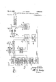
- Figure l shows a block diagram of one embodiment of the present invention
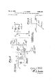
- Figure 2 shows a schematic diagram of a chrominance signal amplifier whose gain is changed synchronously with the frequency and phase of the chrominance signal subcarn'er; r
- Figure 3 shows a vector diagram illustrating the phases and amplitudes of the R-Y, B-Y, and G-Y color difference signals relative to the color synchronizing bursts;
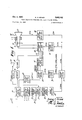
- FIG. 4 shows by block diagram another form of this invention.
- the luminance or monochrome information (Y signal) which represents the relative luminanceor brightness information of the scene is made up of component color signals according to the proportions of 59% green, 30% red and 11% blue.
- color difference signals which indicate how each color in the televised scene differs from the color content of the corresponding color in the luminance signal.
- Color difference signals of the type such as R-Y, G-Y and B-Y, to name only a few of the wide Patented'Oct. 4, 1969 variety of hues and .color difference signals which are transmitted, are included on a suppressed carrier modulated color subcarrier whose modulation phase yields an indication of hue through a wide gamut of colors and Whose amplitude yields an indication of color saturation.
- Color difference signals are available in the modulated color subcarrier either simultaneously or sequentially by utilizing suitable continuous or sequentialprocesses of synchronous detection or envelope sampling at phases which are directly related to the hue or color difference signals desired.
- Color difference signals of the type such as R-Y, B--Y and G-Y do not exist at identical relative amplitudes in the modulated color subcarrier.
- the terminology, relative amplitude of a color difference signal refers to the amplitude of that color difference signal as compared to the amplitude ofthe luminance signal for the condition whereby that color difference signal resultsy ina saturated color.
- the amplitudes of the R-Y, B-Y and G-Y color difference signals are re-A lated according the proportions 0.877, 0.493, and 1.423 respectively, for reproducing saturated primaries and their complements.
- the color subcarrier is demodulated to produce these signals, with these signals utilized for reconstruction of the transmitted color image, then, regardless of whether this utilization be in terms of continuous color diiference signals or in terms of a prescribed sequence of color difference signals, it is important that these variations and relative amplitudes be taken into consideration.
- the color difference signal information is then combined with the Y information in a suitable adder circuit, or possibly ⁇ in the control structure of the color image reproducer itself by applying the Y information, for example, to the cathode and the R-Y, B-Y and G-Y color difference signals to suitable control electrodes.
- the present invention in one of its forms, is concerned with color television receivers employing color image reproducers requiring a sequence of properly balanced color image information applied to appropriate control electrodes of the color image reproducer.
- the incoming television signal arrives at the antenna 11 and is applied to the television signal receiver 13.l
- the televisionsignal receiver 13 includes the functions of first detection, intermediate frequency amplification, second detection, and automatic gain control. Many of these functions are described, ⁇ for example, in Chapter 22 of the book, Harmonics, Sidebands and Transients in Communication,Engineering, by C. Louis Cuccia, published by the McGraw-Hill Book Company in 1952.
- Sound information may be recovered by utilizing,v for example, the well known principles of intercarrier sound in the detector and amplifier 15; the recovered and amplied sound information is then applied -to the loud speaker Y 3
- the color television signal is accommodated in at least four channels of the color television receiver. g These channels are employed for delivering the luminance,
- the deflection system and highvoltage supply 21 not only supply the vertical and horizontal deection signals to the .yokes 23 but also high voltage to the ultor 25 and provides for energizing thekickback voltage generator 27.
- the kickback voltage generatoren ⁇ maybe included in the cir-cuit in the form of Ya multivibrator which is energized by .the horizontal deection signals or maybe j constructed lin the form of Va winding included on, the
- the kickback voltage generator performs the function of supplying a igate'pulse 2.9 during Vthe horizontal blanking period.
- This gate pulse 29 controls the burst ,separator 31 which is a gate circuit to which is applied.
- the gating pulse 29 opens the gateV during the in-V teryal of thecolorsynchronizing burst.
- the separated burst is: applied tothey burst Vsync reference signal source Y rnc. signal having a phase which will .be useful for utilizatcomponents which do not lie in the range from substan- Y tially 3 to 4.2 mcs.
- the output signals from the band pass filter 37 and the Y amplifier 41 are applied to the synchronous gain controlled amplifier 43 wherein the gain is changed at the chrominance subcarrier frequency.
- the synchronous gain controlled amplifier 43 is controlled by a 3.58 me. reference signal provided by the phase and amplitude adjusting circuit 4S.
- the 3.58 mc. refer-V ence signal is also Vsupplied Vin properv phase ⁇ to the control grid switching circuit 47 lwhich develops at terminals 51 and 53 a control wave employed toV guide they electron beam of the color switching sequential display deviceY 19 to elemental color areas on the target corresponding to the color signal which is being applied to the cathode 18 and the control grid 26.
- the chrorninance signal cannot be appliedwithout modification to the image reproducing device 19.
- the modified'chrorninance may then be applied to the color switching sequential device 19.
- the 'synchronous gainV vcontrolled i amplifier circuit shown in Figure 2 operates'inc'onjunction withi'theV color Yswitching sequential display device 19 inainanner whereby' demodulation is effectively ⁇ V performed within the color switching sequentialdisplay device 19(
- the circuit illustratedY in Figure 2 is given by way of example, of the circuits embodyinga'separate.
- demodulator vto provide color diiferencesignals which can be utilized in conjunc-V 4- tion with synchronous gain controlled amplifiers and an appropriate type of color image reproducer.
- the color'television signal is applied to the input terminal 57 of the band pass filter 37.
- the band pass lter 37 comprises a pair of coupled circuits having a resonant primary 60 and a resonant secondary 62.
- the resonant primary 69 and the resonant secondary -6-2 are both tuned and coupled in a manner which yields a pass band from substantially 3 to 4.2 mcs.
- the resonant secondary '62 is connected so that its inductance is center tapped to ground, with the out-put terminals then connected so that the chroma or fiitered color television signal is impressed in one phase on the Vcontrol grid of the tube 61 and an inverted phase at the control grid of the tube 63.
- the information which reaches the control grids ofthe tubes 61 and 63 is still in the form of a color modulator subcarrier or chrominance signal, hereinafter referred to as chroma,V whoseY subcairrier frequency is 3.58 mcs.
- the signd provided by the phase and amplitude adjuster '45 shown in Figure l is Van appropriately phased 3.758 mc. signal which isV developed across the inductance 65 in a. mannerwhich controls the potential of the mutually connected cathodes of tubes 61 and 63.
- the gain of tubes 61 and 63 is therefore controlled by the signals from the phase and amplitude adjuster to an extent depending upon the amplitude of the signal; because the circuit is balanced, the syn-V chronous gain control amplifier 43 does not perform the function of demodulation.
- the output load of tube 61 is vthe output circuit 67; the output load of the tube 63 is the output circuit 69.
- Output circuits 67 and 69 both include a resistor in series with an inductance with the resistor and inductance so chosen in value as to yield wide band operation to the amplification functions of tubes 61 and 63.
- the current to the anode of the tube V61 increases as the current to the anode of tube frequency of 3.58 mcst 63 decreases and vice versa.
- This yields an additive effect so far as the potentials developed in the anodes of tubes 61 and 63 are concerned so that the :chroma is delivered at increased gain between the cathode 18 and the control grid 20 of the ⁇ color switching sequential display device 19.
- the use of ⁇ the RC network 73 is used to prevent surges from damaging the cathode 18 of the color switching sequential display device19.
- the color VdernodulatingV action that takes place in the color switching sequential display device 19 causes a samplingv of the chroma information applied to theV cathode 18 and the control grid 20.
- the color grid switching circuit 47 causes the scanning electron beam of the color switching color display device 19 to impinge on an elemental area having color light output characteristics corresponding to green, for example, the sampling-action yields G-Y information.
- Valso applying the Y information to the anode of tube 61 there is accomplished an addition of the YV and G-Y information during the time interval at which green light emitting cathode luminescent material is'being impinged by the electron beam.
- R--Y information is sampled ⁇ from the chroma and added to the Y to yield red information.
- B-Y infomation is ⁇ sampled in .the chroma and caused to be added to Y ,informationV to yield blue information.
- the gain control wave has a Since the R-Y, B-Y, and G-Y signals are related in amplitude Vaccording to the proportions 0.877, 0.493, and lf423,'respectively, ⁇ when i ussiera the 3.58 mc. gain control wave developed across the inductance 65 is near to its maximum value, the gain of tubes 61 and 63 will be reduced to decrease the level of the G-Y information. When the amplitude of the 3.58 me.
- phase adjuster 35 will also pro-vide sampling phase adjustment so that the proper synchronization of the sampling process will take place within the color switching sequential display device 19.
- the combination of phase adjuster 35 and the phase and amplitude adjuster 45 permits color signal sampling in synchronism with the action of the color grid switching ⁇ circuit 47 thereby resulting in the reconstruction of the color image on the face of the color switching sequential display device 19.
- the balanced gain controlled amplifier 43 is designed to have a wide band output preferably in excess of 7 mcs. so that the modified picture components may be accommodate. After colorbalance has been effected, the 3.58 mc. subcarrier is no longer a wave whose phase and amplitude variations can be described by signal components limited to 4.2 mcs. and as a result a wider pass band amplifier is required.
- FIG. 4 there is shown, for example, a color timing signal producing type of display device 81 utilizing the principles described by Harold B. Law in his U.S. Patent 2,633,547, entitled Two-Sided Electron Sensitive Screen.
- a vertical line phosphor screen Control signals are derived from the electron beam striking the rear surface of the screen on areas of cathode luminescent material. Tubes of this type have employed ultraviolet light-emitting cathode luminescent materials in conjunction with a photocell to provide timing or triggering indicating scanning beam registration. These timing or triggering signals are useful for synchronizing control of the time sequential sampling process or synchronous demodulation of the color information from the chroma information signal.
- the general characteristics of the ci-reuit shown in Figure 4 are similar to those of the circuit shown 'in Figure l.
- the audio information is produced at the loud speaker 17.
- the 3.58 mc. reference signal is developed at the output of the phase adjuster 3S; the chroma signal is available at the loutput of the band pass'tilter 37, and
- Vthe Y signal is available at the terminal 59.
- the Aoutput ⁇ signal ofthe signal at 1.08 mc. is applied to the pass bandyiilter 93 that passes only the 1.08 Ymc. signal.
- TheV 1.08 mc. signaland the outpntof the band pass lter 37 which con.- tainschroma information in the range vfrom approximately 3 to 4.2 mcs., are applied to the heterodyne demodulator 83.
- the output signal of the heterodyne demodulator 83 contains harmonic waves of frequency translated chroma information, now in the frequency range from 1.9 to 3.1 mcs. and having a meansubcarrier frequency of 2.5 mcs.
- the band pass filter and amplifier 95 passes only those harmonic components in the range from 1.9 to 3.1 mcs., and by utilizing suitable phase splitting apparatus, impresses this chroma information Yon the synchronous gain control amplifier 43 in both normal vand reverse polarity.
- the synchronous gain controlled amplifier 43 upon receiving the Y information from the terminal 59 and the 2.5mc. signal as provided by the phase and amplitude adjustment circuit 45, and the chroma information in both normal and reversed polarity from the pass band filter 95 then operates in the manner described in connection with the circuit shown in Figure 2.
- the wide band gain controlled chroma signal is applied between the cathode 18 and the control grid 20, and the Y sigvnal is applied to the cathode 18 of the color image re'- producer ⁇ 81. Time sequential sampling is then produced within the sequential display device 81 in proper phase depending on the adjustments of thek phase adjuster 35 and the phase and amplitude adjuster 45 to yield the recovered color television image.
- a color television receiver comprising in combination, means for developing a subcarrier wave modulated in accordance with a plurality of different selected component colors of a televised image, means for amplifying said subcarrier wave, said amplifying means including heterodyning means for changing the frequency of said subcarrier wave, color balance control means toalter the relative signal amplitudes of said different selected component colors 'as represented in said frequency changed subcarrier wave, said color ⁇ balance control means including a balanced gain control amplifier for said subcarrier wave and a source of a gain control signal consisting of an oscillation at the frequency of said changed subcarrier wave; and means for reproducing said color image from said amplified and altered subcarrier wave.
- a source of phase and amplitude modulated subcarrier wavesV containing modulations derived from color information signals and having a prescribed mean frequency a source of a signal wave having a predetermined waveform, amplitude, and timing, and substantially Ysaid prescribed mean frequency; a gain controlled amplifier ,coupled to said subcarrier wave source and said Ysignal -Wave source forutilizing said signal wave for altering 'the instantaneous amplitude of said phase and amplitude Ymodulated subcarrier waves to provide color balance of said color information signal; and a single-gun tri-color vcolor control electrode.
- Al color television receiver comprising, a color image reproducer having at least a color control terminal and in which different component colors of an image are reproduced selectively at .a predetermined frequency, means for developing at least a color television signal including a .color modulated subcarrier having a mean .frequency corresponding to said predetermined frequency and containing information signals relative'to a plurality of color difference signals of said information, each signal having an associate phase asV compared to a referenceY phase and .a prescribed' relative amplitude level, means for applying said color modulated subcarrier to said color control terminal of said color image reproducer to produce color difference signal demodulation. of said color modulated subcarrier withinsaid color image reproducer, means for developing a signal having'the frequency corresponding to the predetermined frequency, means to control the Yphase and amplitude of the developed signal, and
- ya balanced gain controlled amplifier for varying said color modulated subcarrier in amplitude during prescribed portions of each cycle of vsaid mean color subcarrier frequency whereby the relative amplitude of each component color difference signal demodulated by said color image reproducer is caused to be at an amplitude suitable for correct reconstruction of a transmitted color image by said color image reproducer.
- a color television receiver comprising, a color image reproducer having at least a color control electrode and capable of producing different cemponent colors in sequence atea predetermined frequency
- said color television receiver includingV means for receiving a color television signal including a modulated color subcarrier having 'a mean subcarrier frequencyand containing information signals relative to a plurality of color difference signals each of vsaid information signalsrepresented by a predetermined phase as compared to a reference phase, and each having a'prescribed relative ⁇ amplitude level, means for providing timesequential'sampling of lthe modulated color subcarrier in said ⁇ color image revproducer Ato provide color difference signalsl in sequence when the modulated color subcarrier is applied to said colorV c ontrol electrode at said predetermined frequency;
- Aa color image reproducer including a scanning electron beam andan electron beam sensitive color target area whereon the impingement of said scanning electron beam produces color light emission Yhaving a prescribed color sequence and a frequency ofV component color selection
- control means a source of a color modulated subcarrier having a prescribed mean color subcarrier frequency and containing color difference 4Vinformation signals each having a predetermined phase as compared toa reference phase and each having apresribed relative amplitude levelfvvhenincludedin said color modulated ⁇ subcarrier, means for adiusting the prescribed meanysubcarrierfrequencyof saidvcolo'r modulated subcarrier to said Vfrequency of .component color selectioma source of a signalrwa'vethaving a predetermined wave form of prescribed amplitude and timing and having substantially said frequency of component color selection, ⁇ means' coupled to Vsaid'signal wave source'and .to saidfrequency adjustingrmean's for utilizing said sig- Inal wave for altering the instantaneous amplitude of Asaid frequency adjusting color modulated subcarrier to provide a prescribed color balance of said color difference information signals, and means for coupling said color modulated subcarrier instantan
- aV color .television receiver .the combination of, color image reproducer including a scanning electron beam and an electron beam sensitive color target area Whereon the impingement of scanning electron beam produced Vcolor light emission having a prescribed color sequence at a frequency of component color selection, a source of a color modulated subcarrier having a prescribed mean subcarrier frequency #and containing color difference information signals each having predetermined phase ⁇ as compared to a reference phase, and each having a first prescribed relative amplitude level when in eluded in said color modulated subcarrier, means for developing arrst signal Vhaving said frequency of Vcomponent color selection, means for Fdeveloping a second signal having a frequency which is substantially said prescribed mean subcarrier frequency, a iirst heterodyning means coupled to said first signal means and to said second signal means to develop a third signal having a frequency which is the difference between the frequency of said first signal and the ⁇ frequency of said second signal,
- a color image reproducer having at least a color control having relative amplitudes at atlevel constituting a first degree lof color balance
- a heterodyning circuit coupled to sard color modulated subcarrier source for adjusting Lthe frequency of said color modulated subcarrier to provideY a Ymean frequency of substantially said predetermined frequency at which different component colors of said image are selectively produced on said color image reproducer
- a gain control circuit means operatively'connected with said heterodyning circuit and coupled to said color control termina-l to cause selected portions of each cycle of said heterodyned color modulated subcarrier to be varied in amplitude according toV a second degree of color balance.
- Vsourcerof phasepand amplitude Vmodulated subcarrier waves having a prescribed mean frequency and being representative of different relative amplitudes of respec-V Vtively different color
- Adifference signals atfcertain phases thereof
- a source of a signal wave having substantially said prescribed meanV frequency
- means coupled to said subcarrier Wave source 'and/said signal wave source for utilizing said signal wave to alter the amplitude of said phase and amplitude modulated subcarrier vvaves such as to produce a phase and amplitude modulated subcarrier wave output representative of similar relative amplitudes of said respectively different color difference signals at said certain phases
- said last Vnamed means comprising means coupled to said subcarrier wave source for am 2,955,152 9 10 plifyng said subcarrier waves, and means coupled to 2,736,765 Lohman Feb.
Landscapes
- Engineering & Computer Science (AREA)
- Multimedia (AREA)
- Signal Processing (AREA)
- Processing Of Color Television Signals (AREA)
Description
E.O.KHZER oct. 4, 1960 COLOR TELEVISION RECEIVER WITH COLOR BALANCE CONTROL 3 Sheets-Sheet l Filed Dec. 29, 1954 rhl\m mw E. O. KEIZER Oct. 4, 1960 COLOR TELEVISION RECEIVER WITH COLOR BALANCE CONTROL Filed DeG- 29, 1954 3 Sheets-Sheet 2 :STL A E. O. KEIZER oct. 4, 1960 COLOR TELEVISION RECEIVER WITH COLOR BALANCE CONTROL Filed Dec. 29, 1954 V3 Sheets-Sheet 3 United States Patent COLOR TELEVISION RECEIVERS WITH COLOR BALANCE CONTROL Eugene 0. Keizer, Princeton, NJ., assignor to Radio Corporation of America, a corporation of Delaware Filed Dec. 29, 1954, Ser. No. 478,266
9 Claims. (Cl. 178-5.4)
image in some types of color image reproducers, it is desirable to balance the relative amplitude levels of the color difference signals.
A primary object of this invention is to provide improved color balance in color television receivers.
It is another object of this invention to provide for control of the relative color difference signal amplitudes in color television receivers.
According to the invention, color balance is ob tained by changing the instantaneous relative amplitude of the color difference signals as represented in the chrominance signal channel.
Other and incidental objects of this invention will become apparent from a study of the following detailed description of the accompanying drawings in which:
Figure l shows a block diagram of one embodiment of the present invention;
Figure 2 shows a schematic diagram of a chrominance signal amplifier whose gain is changed synchronously with the frequency and phase of the chrominance signal subcarn'er; r
Figure 3 shows a vector diagram illustrating the phases and amplitudes of the R-Y, B-Y, and G-Y color difference signals relative to the color synchronizing bursts; and
Figure 4 shows by block diagram another form of this invention.
Before entering upon a discussion of the present invention, consider rst some aspects of the color television signal which relate directly to the teachings of the present invention. The luminance or monochrome information (Y signal) which represents the relative luminanceor brightness information of the scene is made up of component color signals according to the proportions of 59% green, 30% red and 11% blue.
'Ihe color or chrominance information is transmitted in the form of color difference signals which indicate how each color in the televised scene differs from the color content of the corresponding color in the luminance signal. Color difference signals of the type such as R-Y, G-Y and B-Y, to name only a few of the wide Patented'Oct. 4, 1969 variety of hues and .color difference signals which are transmitted, are included on a suppressed carrier modulated color subcarrier whose modulation phase yields an indication of hue through a wide gamut of colors and Whose amplitude yields an indication of color saturation. Color difference signals are available in the modulated color subcarrier either simultaneously or sequentially by utilizing suitable continuous or sequentialprocesses of synchronous detection or envelope sampling at phases which are directly related to the hue or color difference signals desired.
Color difference signals of the type such as R-Y, B--Y and G-Y do not exist at identical relative amplitudes in the modulated color subcarrier. The terminology, relative amplitude of a color difference signal, refers to the amplitude of that color difference signal as compared to the amplitude ofthe luminance signal for the condition whereby that color difference signal resultsy ina saturated color. For example, the amplitudes of the R-Y, B-Y and G-Y color difference signals are re-A lated according the proportions 0.877, 0.493, and 1.423 respectively, for reproducing saturated primaries and their complements. If the color subcarrier is demodulated to produce these signals, with these signals utilized for reconstruction of the transmitted color image, then, regardless of whether this utilization be in terms of continuous color diiference signals or in terms of a prescribed sequence of color difference signals, it is importantthat these variations and relative amplitudes be taken into consideration.
Once the color difference signal information has been recovered, it is then combined with the Y information in a suitable adder circuit, or possibly` in the control structure of the color image reproducer itself by applying the Y information, for example, to the cathode and the R-Y, B-Y and G-Y color difference signals to suitable control electrodes.
l The present invention in one of its forms, is concerned with color television receivers employing color image reproducers requiring a sequence of properly balanced color image information applied to appropriate control electrodes of the color image reproducer. v
Consider rst the embodimentof the present invention as incorporated in the color television receiver circuit diagram shown in Figure l. This circuit operates in conjunction with `a color switching sequential display device 19 ofthe type Which performs the function of directing the electron beam to selected elemental areas of an image-target in synchronism with a sequential color information signal which is applied to the control grid 20 and the cathode 18. i
The incoming television signal arrives at the antenna 11 and is applied to the television signal receiver 13.l The televisionsignal receiver 13 includes the functions of first detection, intermediate frequency amplification, second detection, and automatic gain control. Many of these functions are described,`for example, in Chapter 22 of the book, Harmonics, Sidebands and Transients in Communication,Engineering, by C. Louis Cuccia, published by the McGraw-Hill Book Company in 1952.
Sound information may be recovered by utilizing,v for example, the well known principles of intercarrier sound in the detector and amplifier 15; the recovered and amplied sound information is then applied -to the loud speaker Y 3 The color television signal is accommodated in at least four channels of the color television receiver. g These channels are employed for delivering the luminance,
' chrominance and deection signals to the color switching sequential display device 19 and its deflection yokes The deflection system and highvoltage supply 21 not only supply the vertical and horizontal deection signals to the .yokes 23 but also high voltage to the ultor 25 and provides for energizing thekickback voltage generator 27. The kickback voltage generatoren` maybe included in the cir-cuit in the form of Ya multivibrator which is energized by .the horizontal deection signals or maybe j constructed lin the form of Va winding included on, the
horizontal deiiection wave output transformer. The kickback voltage generator performs the function of supplying a igate'pulse 2.9 during Vthe horizontal blanking period. This gate pulse 29 controls the burst ,separator 31 which is a gate circuit to which is applied. the color television signal from the color television signal receiver 13.Y The gating pulse 29 opens the gateV during the in-V teryal of thecolorsynchronizing burst. The separated burst is: applied tothey burst Vsync reference signal source Y rnc. signal having a phase which will .be useful for utilizacomponents which do not lie in the range from substan- Y tially 3 to 4.2 mcs. The output signals from the band pass filter 37 and the Y amplifier 41 are applied to the synchronous gain controlled amplifier 43 wherein the gain is changed at the chrominance subcarrier frequency. The synchronous gain controlled amplifier 43 is controlled by a 3.58 me. reference signal provided by the phase and amplitude adjusting circuit 4S. The 3.58 mc. refer-V ence signal is also Vsupplied Vin properv phase `to the control grid switching circuit 47 lwhich develops at terminals 51 and 53 a control wave employed toV guide they electron beam of the color switching sequential display deviceY 19 to elemental color areas on the target corresponding to the color signal which is being applied to the cathode 18 and the control grid 26.
Since the color -diference'signaln R-Y, B-Y- and G-Y, have different relative amplitude levels in the chrominance signal, the chrorninance signal cannot be appliedwithout modification to the image reproducing device 19. By changing the gain of the chrominance signal amplifier at the 3.58 rnc. rate so that the'relative diiference in amplitude Aof the Vcolor difference signals and therefore the color balance described by these color dif` ference signals is compensatedfor, the modified'chrorninance may then be applied to the color switching sequential device 19. Y j In order to understand more vfully how the'synchronous gain controlled ampljier 43 performs the functions of chrominance signal amplitude control, or color difference signal amplitude level compensation, consider the'operation of the circuit shown in Figure 2 which illustrates oneem'bodiment of the present invention. i
"The 'synchronous gainV vcontrolled i amplifier circuit shown in Figure 2 operates'inc'onjunction withi'theV color Yswitching sequential display device 19 inainanner whereby' demodulation is effectively`V performed within the color switching sequentialdisplay device 19( The circuit illustratedY in Figure 2 is given by way of example, of the circuits embodyinga'separate. demodulator vto provide color diiferencesignals which can be utilized in conjunc-V 4- tion with synchronous gain controlled amplifiers and an appropriate type of color image reproducer.
In Figure 2 the color'television signal is applied to the input terminal 57 of the band pass filter 37. The band pass lter 37 comprises a pair of coupled circuits having a resonant primary 60 and a resonant secondary 62. The resonant primary 69 and the resonant secondary -6-2 are both tuned and coupled in a manner which yields a pass band from substantially 3 to 4.2 mcs. The resonant secondary '62 is connected so that its inductance is center tapped to ground, with the out-put terminals then connected so that the chroma or fiitered color television signal is impressed in one phase on the Vcontrol grid of the tube 61 and an inverted phase at the control grid of the tube 63. The information which reaches the control grids ofthe tubes 61 and 63 is still in the form of a color modulator subcarrier or chrominance signal, hereinafter referred to as chroma,V whoseY subcairrier frequency is 3.58 mcs. The signd provided by the phase and amplitude adjuster '45 shown in Figure l is Van appropriately phased 3.758 mc. signal which isV developed across the inductance 65 in a. mannerwhich controls the potential of the mutually connected cathodes of tubes 61 and 63. The gain of tubes 61 and 63 is therefore controlled by the signals from the phase and amplitude adjuster to an extent depending upon the amplitude of the signal; because the circuit is balanced, the syn-V chronous gain control amplifier 43 does not perform the function of demodulation.
. The output load of tube 61 is vthe output circuit 67; the output load of the tube 63 is the output circuit 69. Output circuits 67 and 69 both include a resistor in series with an inductance with the resistor and inductance so chosen in value as to yield wide band operation to the amplification functions of tubes 61 and 63.
Because the Vchroma signals applied to the grids 61 and 63 are 180 out of phase, the current to the anode of the tube V61 increases as the current to the anode of tube frequency of 3.58 mcst 63 decreases and vice versa. This yields an additive effect so far as the potentials developed in the anodes of tubes 61 and 63 are concerned so that the :chroma is delivered at increased gain between the cathode =18 and the control grid 20 of the` color switching sequential display device 19. The use of `the RC network 73 is used to prevent surges from damaging the cathode 18 of the color switching sequential display device19. j j s The color VdernodulatingV action that takes place in the color switching sequential display device 19 causes a samplingv of the chroma information applied to theV cathode 18 and the control grid 20. For example, when the color grid switching circuit 47 causes the scanning electron beam of the color switching color display device 19 to impinge on an elemental area having color light output characteristics corresponding to green, for example, the sampling-action yields G-Y information. By Valso applying the Y information to the anode of tube 61 there is accomplished an addition of the YV and G-Y information during the time interval at which green light emitting cathode luminescent material is'being impinged by the electron beam. When the electron beam is caused to impinge oncathode luminescentmaterial having red light emitting characteristics, R--Y information is sampled `from the chroma and added to the Y to yield red information. In like manner, when the electron beam is caused to impinge on cathode luminescent material lhaving blue light` emitting characteristics, B-Y infomation is` sampled in .the chroma and caused to be added to Y ,informationV to yield blue information.
The gain control wave applied tothe input terminal 55 and acrossthe cathode impedance consisting of theV inductance 65, serves to simultaneously control the gain of both tubes 61 and 63. The gain control wave has a Since the R-Y, B-Y, and G-Y signals are related in amplitude Vaccording to the proportions 0.877, 0.493, and lf423,'respectively,`when i essaiera the 3.58 mc. gain control wave developed across the inductance 65 is near to its maximum value, the gain of tubes 61 and 63 will be reduced to decrease the level of the G-Y information. When the amplitude of the 3.58 me. gain control wave is near a minimum, the gain of tubes 61 and 63 will be increased to increase thelevel of the B-Y information. "Color balance may thus be accomplished by properly adjusting the phase and amplitude of the 3.58 mc. signal provided by the phase and amplitude adjuster 45 of Figure 1. The phase adjuster 35 of Figure l yields a 3.58 mc. signal to the color grid switching circuit 47 which controls the color switching of the color switching sequential display device 19. Y Y
The phase adjuster 35 will also pro-vide sampling phase adjustment so that the proper synchronization of the sampling process will take place within the color switching sequential display device 19. YThe combination of phase adjuster 35 and the phase and amplitude adjuster 45 permits color signal sampling in synchronism with the action of the color grid switching `circuit 47 thereby resulting in the reconstruction of the color image on the face of the color switching sequential display device 19. In order for high delity picture rendition to be achieved, the balanced gain controlled amplifier 43 is designed to have a wide band output preferably in excess of 7 mcs. so that the modified picture components may be accommodate. After colorbalance has been effected, the 3.58 mc. subcarrier is no longer a wave whose phase and amplitude variations can be described by signal components limited to 4.2 mcs. and as a result a wider pass band amplifier is required.
When the sampling rate and the color information switching rate differs from 3.58 mcs., the present invention may be employed in another one of its forms. In Figure 4, there is shown, for example, a color timing signal producing type of display device 81 utilizing the principles described by Harold B. Law in his U.S. Patent 2,633,547, entitled Two-Sided Electron Sensitive Screen. In the Law patent referred to, there is shown a vertical line phosphor screen, Control signals are derived from the electron beam striking the rear surface of the screen on areas of cathode luminescent material. Tubes of this type have employed ultraviolet light-emitting cathode luminescent materials in conjunction with a photocell to provide timing or triggering indicating scanning beam registration. These timing or triggering signals are useful for synchronizing control of the time sequential sampling process or synchronous demodulation of the color information from the chroma information signal.
Consider the performance of the embodiment shown in Figure V4 wherein the sequential display device Slis @of the type which yields color timing signals depending upon thekposition of the scanning electron beam. It is necessary that suitable color signals be applied to the cathode terminal 18 in the control grid terminalZi) in synchronism with the position of the scanning electron beam as it travels from one color light emitting segment toanother. For the purpose of explanation, it will be assumed 'that the embodiment shown in Figure 4 employs a sequential display device whose sampling frequency is at 2.5 mcs. This 2.5 mc. rate is 1.08 mcs. lower in frequency than the frequency of the color subcarrier.
The general characteristics of the ci-reuit shown in Figure 4 are similar to those of the circuit shown 'in Figure l. The audio information is produced at the loud speaker 17. The 3.58 mc. reference signal is developed at the output of the phase adjuster 3S; the chroma signal is available at the loutput of the band pass'tilter 37, and
Vthe Y signal is available at the terminal 59. The 2.5
to the heterodyne mixer 91. The Aoutput `signal ofthe signal at 1.08 mc. is applied to the pass bandyiilter 93 that passes only the 1.08 Ymc. signal. TheV 1.08 mc. signaland the outpntof the band pass lter 37 which con.- tainschroma information in the range vfrom approximately 3 to 4.2 mcs., are applied to the heterodyne demodulator 83. The output signal of the heterodyne demodulator 83 contains harmonic waves of frequency translated chroma information, now in the frequency range from 1.9 to 3.1 mcs. and having a meansubcarrier frequency of 2.5 mcs. The band pass filter and amplifier 95 passes only those harmonic components in the range from 1.9 to 3.1 mcs., and by utilizing suitable phase splitting apparatus, impresses this chroma information Yon the synchronous gain control amplifier 43 in both normal vand reverse polarity.
The synchronous gain controlled amplifier 43, upon receiving the Y information from the terminal 59 and the 2.5mc. signal as provided by the phase and amplitude adjustment circuit 45, and the chroma information in both normal and reversed polarity from the pass band filter 95 then operates in the manner described in connection with the circuit shown in Figure 2. The wide band gain controlled chroma signal is applied between the cathode 18 and the control grid 20, and the Y sigvnal is applied to the cathode 18 of the color image re'- producer` 81. Time sequential sampling is then produced within the sequential display device 81 in proper phase depending on the adjustments of thek phase adjuster 35 and the phase and amplitude adjuster 45 to yield the recovered color television image.
Having described the invention, what is claimed is:
1. In a signalling system, the combination of, a source of a subcarrier signal having a mean frequency and modulated by a plurality of modulating signals, `and wherein each of said plurality of modulating signals is represented by a predetermined phase of said subcarrier signal and by a predetermined relative amplitude, heterodyning means coupled to said source for changing the frequency of said subcarrier signal from said mean frequency to a second mean frequency, an amplitude control means coupled to said heterodyning means for altering` the instantaneous amplitude of said hetero- 'dyned subcarrier signal at a rate equal to said second mean frequency, a signal utilizationmeans, and means to apply said amplitude altered subcarrier signal to said signal utilization means. l
2. A color television receiver comprising in combination, means for developing a subcarrier wave modulated in accordance with a plurality of different selected component colors of a televised image, means for amplifying said subcarrier wave, said amplifying means including heterodyning means for changing the frequency of said subcarrier wave, color balance control means toalter the relative signal amplitudes of said different selected component colors 'as represented in said frequency changed subcarrier wave, said color` balance control means including a balanced gain control amplifier for said subcarrier wave and a source of a gain control signal consisting of an oscillation at the frequency of said changed subcarrier wave; and means for reproducing said color image from said amplified and altered subcarrier wave.- Y Y .3. In a color television receiver, the combination of, a source of phase and amplitude modulated subcarrier wavesV containing modulations derived from color information signals and having a prescribed mean frequency; a source of a signal wave having a predetermined waveform, amplitude, and timing, and substantially Ysaid prescribed mean frequency; a gain controlled amplifier ,coupled to said subcarrier wave source and said Ysignal -Wave source forutilizing said signal wave for altering 'the instantaneous amplitude of said phase and amplitude Ymodulated subcarrier waves to provide color balance of said color information signal; and a single-gun tri-color vcolor control electrode.
kinescope coupled to the output of said gain controlled amplifier. Y
4. Al color television receiver comprising, a color image reproducer having at least a color control terminal and in which different component colors of an image are reproduced selectively at .a predetermined frequency, means for developing at least a color television signal including a .color modulated subcarrier having a mean .frequency corresponding to said predetermined frequency and containing information signals relative'to a plurality of color difference signals of said information, each signal having an associate phase asV compared to a referenceY phase and .a prescribed' relative amplitude level, means for applying said color modulated subcarrier to said color control terminal of said color image reproducer to produce color difference signal demodulation. of said color modulated subcarrier withinsaid color image reproducer, means for developing a signal having'the frequency corresponding to the predetermined frequency, means to control the Yphase and amplitude of the developed signal, and
ya balanced gain controlled amplifier for varying said color modulated subcarrier in amplitude during prescribed portions of each cycle of vsaid mean color subcarrier frequency whereby the relative amplitude of each component color difference signal demodulated by said color image reproducer is caused to be at an amplitude suitable for correct reconstruction of a transmitted color image by said color image reproducer.
5. A color television receiver comprising, a color image reproducer having at least a color control electrode and capable of producing different cemponent colors in sequence atea predetermined frequency, said color television receiver includingV means for receiving a color television signal including a modulated color subcarrier having 'a mean subcarrier frequencyand containing information signals relative to a plurality of color difference signals each of vsaid information signalsrepresented by a predetermined phase as compared to a reference phase, and each having a'prescribed relative` amplitude level, means for providing timesequential'sampling of lthe modulated color subcarrier in said `color image revproducer Ato provide color difference signalsl in sequence when the modulated color subcarrier is applied to said colorV c ontrol electrode at said predetermined frequency;
jmeans for` producinga signal of mean-subcarrier fre-V quency and having a predetermined phase and amplitude, a gain control means for etectingcolor balance, means Y for applying saidfcolor modulated' subcarrier through said gain control means, means Vto apply said produced signale to said gain control means to control the instan-V e taneous gain of'said gain control means, and means for coupling the output of said gain control means to said Vv6. In a color television receivergrthe combination of,
Aa color image reproducer including a scanning electron beam andan electron beam sensitive color target area whereon the impingement of said scanning electron beam produces color light emission Yhaving a prescribed color sequence and a frequency ofV component color selection,
anelectron beam modulation .control means, a source of a color modulated subcarrier having a prescribed mean color subcarrier frequency and containing color difference 4Vinformation signals each having a predetermined phase as compared toa reference phase and each having apresribed relative amplitude levelfvvhenincludedin said color modulated` subcarrier, means for adiusting the prescribed meanysubcarrierfrequencyof saidvcolo'r modulated subcarrier to said Vfrequency of .component color selectioma source of a signalrwa'vethaving a predetermined wave form of prescribed amplitude and timing and having substantially said frequency of component color selection, `means' coupled to Vsaid'signal wave source'and .to saidfrequency adjustingrmean's for utilizing said sig- Inal wave for altering the instantaneous amplitude of Asaid frequency adjusting color modulated subcarrier to provide a prescribed color balance of said color difference information signals, and means for coupling said color modulated subcarrier instantaneous'. amplitude altering means to said electron beammodulation control means. 7. In aV color .television receiver, .the combination of, color image reproducer including a scanning electron beam and an electron beam sensitive color target area Whereon the impingement of scanning electron beam produced Vcolor light emission having a prescribed color sequence at a frequency of component color selection, a source of a color modulated subcarrier having a prescribed mean subcarrier frequency #and containing color difference information signals each having predetermined phase `as compared to a reference phase, and each having a first prescribed relative amplitude level when in eluded in said color modulated subcarrier, means for developing arrst signal Vhaving said frequency of Vcomponent color selection, means for Fdeveloping a second signal having a frequency which is substantially said prescribed mean subcarrier frequency, a iirst heterodyning means coupled to said first signal means and to said second signal means to develop a third signal having a frequency which is the difference between the frequency of said first signal and the `frequency of said second signal, a second heterodyning means coupled to said first heterodyning means and said color modulated subcarrier source for developing a frequency .altered color modulated subcarrier having a mean frequency at said frequency of said component color selection, signal ampli tude control means coupled tosaid second heterodyning means andto said iirst signal means for altering the relative amplitude of each of the color difference information signals contained in said second frequency altered color modulated subcarrier, and means coupled 'to said amplitude control means and to said electron beam modu- Y lation control means for'utilizing said amplitude altered second frequency altered color modulated subcarrier to modulate s-aid scanning electron beam.
8. In a color television receiver, the combination of,
t a color image reproducer having at least a color control having relative amplitudes at atlevel constituting a first degree lof color balance, a heterodyning circuit coupled to sard color modulated subcarrier source for adjusting Lthe frequency of said color modulated subcarrier to provideY a Ymean frequency of substantially said predetermined frequency at which different component colors of said image are selectively produced on said color image reproducer, a gain control circuit means operatively'connected with said heterodyning circuit and coupled to said color control termina-l to cause selected portions of each cycle of said heterodyned color modulated subcarrier to be varied in amplitude according toV a second degree of color balance. Y Y 9. Ina color television receiver, the combination of Vsourcerof phasepand amplitude Vmodulated subcarrier waves having a prescribed mean frequency and being representative of different relative amplitudes of respec-V Vtively different color Adifference signals atfcertain phases thereof, a source of a signal wave having substantially said prescribed meanV frequency, means coupled to said subcarrier Wave source 'and/said signal wave source for utilizing said signal wave to alter the amplitude of said phase and amplitude modulated subcarrier vvaves such as to produce a phase and amplitude modulated subcarrier wave output representative of similar relative amplitudes of said respectively different color difference signals at said certain phases, said last Vnamed means comprising means coupled to said subcarrier wave source for am 2,955,152 9 10 plifyng said subcarrier waves, and means coupled to 2,736,765 Lohman Feb. 28, 1956 said signal wave source for controlling the gain of said 2,757,229 Larky July 31, 1956 amplifying means in accordance with said signal wave. 2,798,900 Bradley July 9, 1957 2,891,152 Altes June 16, 1959 References Cited in the le of this patent 5 OTHER REFERENCES UNITED STATESPATENTS Color Tv, Rider Pub., March 1954, pp. 141 and 142. 2,653,187 Barton Sept. 22, 1953 Copy nDiv. 16.
Rhodes .Tune 1, 1954 Schroeder June 15, 1954 Introduction to Color Television, Admiral Corp., February 1954, pages 17 to 27. Copy in Div. 16.
Priority Applications (1)
| Application Number | Priority Date | Filing Date | Title |
|---|---|---|---|
| US478266A US2955152A (en) | 1954-12-29 | 1954-12-29 | Color television receivers with color balance control |
Applications Claiming Priority (1)
| Application Number | Priority Date | Filing Date | Title |
|---|---|---|---|
| US478266A US2955152A (en) | 1954-12-29 | 1954-12-29 | Color television receivers with color balance control |
Publications (1)
| Publication Number | Publication Date |
|---|---|
| US2955152A true US2955152A (en) | 1960-10-04 |
Family
ID=23899216
Family Applications (1)
| Application Number | Title | Priority Date | Filing Date |
|---|---|---|---|
| US478266A Expired - Lifetime US2955152A (en) | 1954-12-29 | 1954-12-29 | Color television receivers with color balance control |
Country Status (1)
| Country | Link |
|---|---|
| US (1) | US2955152A (en) |
Cited By (7)
| Publication number | Priority date | Publication date | Assignee | Title |
|---|---|---|---|---|
| US3135824A (en) * | 1960-02-01 | 1964-06-02 | Philco Corp | Shift of color balance in indexing tube between monochrome and color reception |
| US3213190A (en) * | 1960-05-09 | 1965-10-19 | Philco Corp | Color balance control for a single gun color television receiver |
| US3301945A (en) * | 1964-07-01 | 1967-01-31 | Admiral Corp | Automatic color temperature control |
| US3382317A (en) * | 1964-10-15 | 1968-05-07 | Polaroid Corp | Color television receiver using switched synchronous demodulator |
| US3479449A (en) * | 1966-12-08 | 1969-11-18 | Sylvania Electric Prod | Color temperature stabilization in color receivers |
| US3562410A (en) * | 1968-06-19 | 1971-02-09 | Electrohome Ltd | Color tone control networks for color television receivers |
| US3678397A (en) * | 1969-10-31 | 1972-07-18 | Bell & Howell Co | Apparatus for correcting phase shifts in angle-modulated signals |
Citations (7)
| Publication number | Priority date | Publication date | Assignee | Title |
|---|---|---|---|---|
| US2653187A (en) * | 1950-04-04 | 1953-09-22 | Rca Corp | Synchronizing apparatus |
| US2680147A (en) * | 1952-12-31 | 1954-06-01 | Rca Corp | Distortion eliminator |
| US2681379A (en) * | 1951-04-27 | 1954-06-15 | Rca Corp | Signal operated automatic color control circuits |
| US2736765A (en) * | 1953-07-27 | 1956-02-28 | Rca Corp | Automatic switching |
| US2757229A (en) * | 1951-06-07 | 1956-07-31 | Rca Corp | Automatic chroma control circuit |
| US2798900A (en) * | 1951-02-02 | 1957-07-09 | Philco Corp | Gain control system for color television receiver |
| US2891152A (en) * | 1954-06-29 | 1959-06-16 | Gen Electric | Signal-modifying device |
-
1954
- 1954-12-29 US US478266A patent/US2955152A/en not_active Expired - Lifetime
Patent Citations (7)
| Publication number | Priority date | Publication date | Assignee | Title |
|---|---|---|---|---|
| US2653187A (en) * | 1950-04-04 | 1953-09-22 | Rca Corp | Synchronizing apparatus |
| US2798900A (en) * | 1951-02-02 | 1957-07-09 | Philco Corp | Gain control system for color television receiver |
| US2681379A (en) * | 1951-04-27 | 1954-06-15 | Rca Corp | Signal operated automatic color control circuits |
| US2757229A (en) * | 1951-06-07 | 1956-07-31 | Rca Corp | Automatic chroma control circuit |
| US2680147A (en) * | 1952-12-31 | 1954-06-01 | Rca Corp | Distortion eliminator |
| US2736765A (en) * | 1953-07-27 | 1956-02-28 | Rca Corp | Automatic switching |
| US2891152A (en) * | 1954-06-29 | 1959-06-16 | Gen Electric | Signal-modifying device |
Cited By (7)
| Publication number | Priority date | Publication date | Assignee | Title |
|---|---|---|---|---|
| US3135824A (en) * | 1960-02-01 | 1964-06-02 | Philco Corp | Shift of color balance in indexing tube between monochrome and color reception |
| US3213190A (en) * | 1960-05-09 | 1965-10-19 | Philco Corp | Color balance control for a single gun color television receiver |
| US3301945A (en) * | 1964-07-01 | 1967-01-31 | Admiral Corp | Automatic color temperature control |
| US3382317A (en) * | 1964-10-15 | 1968-05-07 | Polaroid Corp | Color television receiver using switched synchronous demodulator |
| US3479449A (en) * | 1966-12-08 | 1969-11-18 | Sylvania Electric Prod | Color temperature stabilization in color receivers |
| US3562410A (en) * | 1968-06-19 | 1971-02-09 | Electrohome Ltd | Color tone control networks for color television receivers |
| US3678397A (en) * | 1969-10-31 | 1972-07-18 | Bell & Howell Co | Apparatus for correcting phase shifts in angle-modulated signals |
Similar Documents
| Publication | Publication Date | Title |
|---|---|---|
| US2885465A (en) | Image-reproducing system for a color-television receiver | |
| USRE26852E (en) | Richman phase detector and color killer | |
| US2955152A (en) | Color television receivers with color balance control | |
| US2712568A (en) | Color synchronization | |
| US2814778A (en) | Signal-modifying apparatus | |
| US3301945A (en) | Automatic color temperature control | |
| US3272916A (en) | Color television systems utilizing a true luminance signal | |
| US2750440A (en) | Synchronous detection at intermediate frequency level of color subcarrier | |
| US2835728A (en) | Television receiver with color signal gate | |
| US2908752A (en) | Color signal demodulating and matrixing | |
| US2845481A (en) | Color television | |
| US3134850A (en) | Color television control apparatus | |
| US2885464A (en) | Color or monochrome image-repro-ducing apparatus | |
| US3382317A (en) | Color television receiver using switched synchronous demodulator | |
| US3294898A (en) | Compatible color television | |
| US2924649A (en) | Adaptation of standard color signal for use with vertical strip color tube | |
| US2890273A (en) | Wave-signal modifying apparatus | |
| US2897263A (en) | Color reproduction using brightness signal alone as substitute for green signal | |
| US2858367A (en) | Color television | |
| US2832819A (en) | Color television | |
| US3405230A (en) | Color television demodulation system | |
| US3303275A (en) | Video signal reproducing system for color television receiver | |
| US3535438A (en) | Demodulation system | |
| US2980760A (en) | Automatic gain control of demodulating signals | |
| US2896013A (en) | Color television receiver |