US2945346A - Reverse thrust brake - Google Patents
Reverse thrust brake Download PDFInfo
- Publication number
- US2945346A US2945346A US459886A US45988654A US2945346A US 2945346 A US2945346 A US 2945346A US 459886 A US459886 A US 459886A US 45988654 A US45988654 A US 45988654A US 2945346 A US2945346 A US 2945346A
- Authority
- US
- United States
- Prior art keywords
- aircraft
- exhaust pipe
- doors
- engine
- housing
- Prior art date
- Legal status (The legal status is an assumption and is not a legal conclusion. Google has not performed a legal analysis and makes no representation as to the accuracy of the status listed.)
- Expired - Lifetime
Links
Images


Classifications
-
- F—MECHANICAL ENGINEERING; LIGHTING; HEATING; WEAPONS; BLASTING
- F02—COMBUSTION ENGINES; HOT-GAS OR COMBUSTION-PRODUCT ENGINE PLANTS
- F02K—JET-PROPULSION PLANTS
- F02K1/00—Plants characterised by the form or arrangement of the jet pipe or nozzle; Jet pipes or nozzles peculiar thereto
- F02K1/54—Nozzles having means for reversing jet thrust
- F02K1/56—Reversing jet main flow
- F02K1/60—Reversing jet main flow by blocking the rearward discharge by means of pivoted eyelids or clamshells, e.g. target-type reversers
Definitions
- This invention relates to reverse thrust brakes for jet engines and more particularly to an improved reverse thrust mechanism, primarily designed for aircraft employing jet engines, which may be retracted completely within the aircraft during normal flight to the end that the external surface or aerodynamic contour of the aircraft will be unbroken thereby and the means by which said mechanism is operated.
- the present invention proposes a controlled, operating mechanism which may be incorporated in an aircraft to so direct the exhaust gases from the engine thereof that both forward and backward or reverse thrust of the aircraft may be effected.
- the instant, invention contemplates means whereby the mechanism may be retracted totally within an aircraft during the normal forward propulsive operation of the aircraftlest it adversely afiect forward speed or create drag. Moreover, when so retracted, it forms an unbroken continuation of the internal walls defining the passage or duct through which the exhaust gases pass during normal flight of the aircraft.
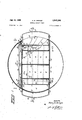
- Fig. 1 is a transverse section taken through a housing, e.g., a nacelle, fuselage, etc., which encloses the exhaust passage or duct of a jet engine to show the present reverse thrust brake disposed therein in its operative position with various portions thereof broken away to show the means by which the brake is actuated to and from this position;
- a housing e.g., a nacelle, fuselage, etc.
- Fig. 2 is a section taken partially along line 2-2 and partially along line 2*2 of Fig. 1 with the associated wall of the exhaust duct removed to show in full lines the entire actuating mechanism for operation of the instant reverse thrust brake;
- Fig. 3 is a view like Fig. 2 to show the present brake disposed in its inoperative position.
- reverse thrust devices heretofore proposed have proven unsatisfactory and, therefore have been rejected because all of these devices either project from the aircraft into, so as to break or interrupt, the aerodynamic contour thereof or project internally of the aircraft into the exhaust passage. In either case they adversely affect the operation of the aircraft during normal flight, i.e. in the first instance they create drag or resistance to forward propulsion and in the second instance they reduce the thrust or propulsive force developed by the engine.
- the present mechanism particularly lends itself for navigation or short radius steering both on ground and on water.
- a positive or forward thrust of the engine or engines operative on one side of the aircraft and a negative or reverse thrust on the engines operative on the opposed side will effect the sharpest possible turning of the aircraft.
- 10 designates a fragmentary portion of a jet engine housing or nacelle adjacent the area thereof in which it is de sired to locate the present mechanism.
- An extension 11 of the shroud in which the associated jet engine (not shown) is contained passes through this area of the housing 10.
- the jet engine is provided with, and terminates in, 'a tail pipe -12 which is disposed substantially centrally within the shroud 11 for the passage of exhaust gases from the engine.
- Diametrically opposed portions of the tail pipe 12 are removed throughout the length of this area of the housing 10 in which the present mechanism is located and the remaining opposed portions of the pipe 12 therebetween are flattened out to create a pair of parallelly disposed side walls 12'. Aft of this area each ofthese walls 12 reconverge into a continuation of the tail pipe 12 as it exists forward of the removed portions just described.
- Theopposite open portions of the tail pipe 12 are closed by a pair of opposed flat walls 13 and 14 respectively whereby a substantially rectangular cross-section is formed.
- Each of the walls 13 and 14 extends transversely of the housing 10 to abut the opposed inner walls thereof.
- a plurality of vanesor louvers 15 are each fixedly secured to the outer corresponding ends of the walls 13 and 14, .to be disposed in and transversely fill and close, the space defined by the outer wall of the exhaust pipe 12 and the inner wall or skin of the housing 10.
- an angle bracket 16 is riveted, or otherwise secured, at the ends of each louver 15 and to the associated inner face of the walls 13 and 14.
- Each of these angles 16 extends along the entire width of its associated louver '15 whereby each louver is rigidly secured so as to become, in effect, an integral part of the walls 13 and 14.
- the skin or wall of the housing between each group of louvers on opposed sides of the housing 11) is cut away, as at 17.
- the shroud 11 is interrupted in its length between the first and last louver 15 of each opposed group whereby the internal passage in exhaust pipe 12 is in open communication with the outside of the housing 10.
- a pair of identical gates or doors 18 are each pivotally mounted on corresponding outer ends of the walls 13 and 14 on a shaft 19 which extends between, and pierces, the walls 13 and 14 in which it is rotatably mounted in any common and well-known manner such as, for example, by means of a bearing 20.
- the shafts 19 are identical one with the other and synnnetrically disposed about the longitudinal axis of the housing 16 in a common transverse plane whereby the free or outer ends of the gates 18 abut in the longitudinal center of the exhaust pipe 12 upon the rotation thereof.
- Each door 18 is generally triangular or wedge-shaped in cross-section being secured, or splined, to its respective shaft 19 adjacent the base thereof with its apex designed to terminate at the longitudinal centerline of the housing 10.
- each door 18 may consist of a pair of substantially rectangular plates or sheets 21 conforming in shape, when disposed with their outer or free ends in abutment (Fig. 1), to the cross-sectional area of the exhaust pipe 12 defined by the side walls 12, 13 and 14. These sheets 21 are secured one to the other by means of and through a plurality of transverse ribs 22 which are riveted or otherwise fastened to the associated faces of the sheets.
- a number of lightening holes 23 may he provided in each of the ribs 22 and that portion of any or all of the ribs 22 through which the shafts 19 pass may be enlarged, as at 24, to form an inregral socket for structural purposes.
- each door 18 may, if desired or required, be provided with a plurality of relatively small apertures 25 to vent or bleed a predetermined quantity of the gases passing through the exhaust pipe 12 for reasons which will become more apparent upon subsequent disclosure of the operation of the invention.
- each shaft 19 is pivotally secured in a bearing 26 which is appropriately secured to, so as to become, in eflect, an immovable part of, stationary structure internally of the housing 10 in any suitable and well-known manner.
- the doors 18 are concurrently rotated internally of the exhaust pipe 12 to a position where the free ends thereof abut in the longitudinal center of the exhaust pipe 12. With the doors 18 so disposed, the exhaust pipe 12 is completely closed and gases from the engine, located forwardly thereof, are directed or deflected to pass out of the housing 10 through the openings 17 between the fixed vanes or louvers 15 (Fig. 2).
- Rotation of the shafts 19 in the opposite direction serves to concurrently move the doors 18 outwardly of the exhaust pipe 12 to a position where the outer faces thereof abut the inner ends of the louvers 15.
- the inner face or wall of each door 18 forms a continuation of the inner surfaces of the side walls 12' of the exhaust pipe 12 whereby the gases from the engine are allowed to pass without restriction through the entire length of the exhaust pipe 12 (Fig. 3).
- the power unit 31 is fixedly mounted to stationary structure forming an integral part of the housing 10in any suitable and well-known manner, and is provided with conventional fittings whereby inlet and outlet lines may be connected thereto for its operation.
- the invention contemplates that the control lever or switch by which the power unit 30 is actuated be located in the cockpit or cab of the vehicle employing the jet engine for the convenient handling thereof by the pilot or operator.
- auxiliary doors 31 are provided, one being disposed between each pair of adjacent louvers 15. These auxiliary doors 31 also serve as nozzles or extension louvers to augment the effective thrust of exhaust gases passing therethrough when the mechanism is disposed in its operative position.
- each auxiliary door 31 comprises an arcuate plate 31 conforming in shape and area to each of the openings 17 in the skin of housing 10. At each of its ends the plate 31' terminates in an integral flange 31" which is generally triangular or pie-shaped.
- a stud shaft 32 is secured to and pierces each flange 31 on corresponding ends of the doors 31 adjacent the apex end of said flange and extends from its respective door 31 in the direction of the wall 13 which it also pierces.
- These ends of the shafts 32 are each provided with a horn or lever 33 which is fixedly secured thereto.
- the opposite end of each of the horns 33 is pivotally attached by means of a bolt or pin 34 to an inter-connecting rod 35 for the operation of all of the several shafts 32 in unison.
- horns 33 are provided with an extension 36, the outer end of which is pivotally secured to a driving link 37 by a pin 38.
- the link 37 is similarly connected to the outer end of an ex tension arm 39 integrally projecting from, so as to be diametrically opposed to, the associated operating lever 27.
- the auxiliary doors 31 are concurrently actuated to a position where they project outwardly of the housing 10. In this position the inner and outer surfaces of the several doors 31 form a continuation of the corresponding surfaces of their respective louvers 15 and thereby serve as nozzles to direct the outward jet of the gases.
- the apertures 25 therein permit a relatively small leakage of gas therethrough. This serves to prevent a suction in the exhaust pipe 12 immediately aft of the doors 18 which could conceivably draw or suck the doors beyond their intended limit of movement whereby they might become distorted and inoperative.
- supplemental power may be obtained by a duplicate actuating mechanism operative on the shafts 19 at the other end thereof.
- a mechanism would include a power unit 30, operating levers 27, extension arms 39, driving links 37, interconnecting rods 35, horns 33 and studs 32 all organized and arranged for operations as hereinabove described.
Description
July 19, 1960 H. E. ARNZEN REVERSE THRUST BRAKE 3 Sheets-Sheet 1 Filed Oct. 4, 1954 IN V EN TOR. flemyfi/im en 9A QM ATTORNEY.
July 19, 1960 H. E. ARNZEN REVERSE THRUST BRAKE 3 Sheets-She t 3 Filed Oct. 4, 195
INVENTOR. Henry 5, 1477233 BY 9d, ATTORNEY.
atcnt REVERSE THRUST BRAKE Henry E. Arnzen, Amityville, N.Y., assignor to Republic Aviation Corporation, near Farmingdale, N .Y., a corporation of Delaware Filed Oct. 4, 1954, Ser. No. 459,886
3 Claims. (Cl. 60--35.54)
This invention relates to reverse thrust brakes for jet engines and more particularly to an improved reverse thrust mechanism, primarily designed for aircraft employing jet engines, which may be retracted completely within the aircraft during normal flight to the end that the external surface or aerodynamic contour of the aircraft will be unbroken thereby and the means by which said mechanism is operated.
The present invention, among other things, proposes a controlled, operating mechanism which may be incorporated in an aircraft to so direct the exhaust gases from the engine thereof that both forward and backward or reverse thrust of the aircraft may be effected.
At the same time the instant, invention contemplates means whereby the mechanism may be retracted totally within an aircraft during the normal forward propulsive operation of the aircraftlest it adversely afiect forward speed or create drag. Moreover, when so retracted, it forms an unbroken continuation of the internal walls defining the passage or duct through which the exhaust gases pass during normal flight of the aircraft.
With the above and other objects in view, as will be apparent, this invention consists in the construction, combination and arrangement of parts all as hereinafter more fully described, claimed and illustrated in the accompanying drawings, wherein:
Fig. 1 is a transverse section taken through a housing, e.g., a nacelle, fuselage, etc., which encloses the exhaust passage or duct of a jet engine to show the present reverse thrust brake disposed therein in its operative position with various portions thereof broken away to show the means by which the brake is actuated to and from this position;
Fig. 2 is a section taken partially along line 2-2 and partially along line 2*2 of Fig. 1 with the associated wall of the exhaust duct removed to show in full lines the entire actuating mechanism for operation of the instant reverse thrust brake; and
Fig. 3 is a view like Fig. 2 to show the present brake disposed in its inoperative position.
Reverse thrust mechanisms per se are admittedly old in the art. These devices, however, have, without exception, been ineffectual in their intended purpose and have not been adopted with any appreciable success for one reason and another. The most common objection to the best of these prior mechanisms is that they are unduly complex and, therefore, prone to fail in an emergency or even in extended normal service and/or they are cumbersome, bulky and undesirably heavy. These shortcomings of existing reverse thrust devices are especially intolerable in aircraft where Weight and internal space available for such equipment is at a premium.
Additionally, reverse thrust devices heretofore proposed have proven unsatisfactory and, therefore have been rejected because all of these devices either project from the aircraft into, so as to break or interrupt, the aerodynamic contour thereof or project internally of the aircraft into the exhaust passage. In either case they adversely affect the operation of the aircraft during normal flight, i.e. in the first instance they create drag or resistance to forward propulsion and in the second instance they reduce the thrust or propulsive force developed by the engine.
It is the purpose of the present invention to overcome the foregoing as well as other objections. To that end a pilot-controlled mechanism is proposed for reversing the direction of thrust developed by the jet engine of an aircraft which, when not in actual operation, may be retracted completely within the airframe whereby smooth and continuous internal, as well as external, surfaces are formed. Thus, during normal flight of the aircraft, when the present reverse thrust mechanism is inoperative, it imposes no parasite load on the aircraft either in the form of drag or in a reduction of thrust produced by the engine.
With the instant reverse thrust mechanism, landing of the aircraft can be accomplished on a landing strip or runway of minimum length, since the distance required for deceleration, i.e. bringing the aircraft to a stop upon landing, is materially reduced. This has become, and will continue to be, of major importance due to the everincreasing speed of aircraft with a concurrent increase in landing or touch-down speed. Surface controls or flaps and brakes alone have proven to be totally incapable of safely stopping present-day high speed aircraft after touch-down on existing runways or even on runways which have been reasonably extended.
Additionally, in multi-engine airplanes the present mechanism particularly lends itself for navigation or short radius steering both on ground and on water. Thus, a positive or forward thrust of the engine or engines operative on one side of the aircraft and a negative or reverse thrust on the engines operative on the opposed side will effect the sharpest possible turning of the aircraft.
It is also possible, by means of this invention, to control air-speed and flight operations of the aircraft generally. Not only is such control advantageous in reducing the speed or braking the aircraft prior to landing, but it also permits steeper diving attitudes for accuracy in dive-bombing, strafing, etc. particularly important with respect to fighter aircraft.
Referring more particularly now to the drawings, 10 designates a fragmentary portion of a jet engine housing or nacelle adjacent the area thereof in which it is de sired to locate the present mechanism. An extension 11 of the shroud in which the associated jet engine (not shown) is contained passes through this area of the housing 10. The jet engine is provided with, and terminates in, 'a tail pipe -12 which is disposed substantially centrally within the shroud 11 for the passage of exhaust gases from the engine.
Diametrically opposed portions of the tail pipe 12 are removed throughout the length of this area of the housing 10 in which the present mechanism is located and the remaining opposed portions of the pipe 12 therebetween are flattened out to create a pair of parallelly disposed side walls 12'. Aft of this area each ofthese walls 12 reconverge into a continuation of the tail pipe 12 as it exists forward of the removed portions just described.
Theopposite open portions of the tail pipe 12 thus created are closed by a pair of opposed flat walls 13 and 14 respectively whereby a substantially rectangular cross-section is formed. Each of the walls 13 and 14 extends transversely of the housing 10 to abut the opposed inner walls thereof. A plurality of vanesor louvers 15 are each fixedly secured to the outer corresponding ends of the walls 13 and 14, .to be disposed in and transversely fill and close, the space defined by the outer wall of the exhaust pipe 12 and the inner wall or skin of the housing 10. To this end an angle bracket 16 is riveted, or otherwise secured, at the ends of each louver 15 and to the associated inner face of the walls 13 and 14. Each of these angles 16 extends along the entire width of its associated louver '15 whereby each louver is rigidly secured so as to become, in effect, an integral part of the walls 13 and 14.
The skin or wall of the housing between each group of louvers on opposed sides of the housing 11) is cut away, as at 17. The shroud 11 is interrupted in its length between the first and last louver 15 of each opposed group whereby the internal passage in exhaust pipe 12 is in open communication with the outside of the housing 10.
A pair of identical gates or doors 18 are each pivotally mounted on corresponding outer ends of the walls 13 and 14 on a shaft 19 which extends between, and pierces, the walls 13 and 14 in which it is rotatably mounted in any common and well-known manner such as, for example, by means of a bearing 20. The shafts 19 are identical one with the other and synnnetrically disposed about the longitudinal axis of the housing 16 in a common transverse plane whereby the free or outer ends of the gates 18 abut in the longitudinal center of the exhaust pipe 12 upon the rotation thereof.
Each door 18 is generally triangular or wedge-shaped in cross-section being secured, or splined, to its respective shaft 19 adjacent the base thereof with its apex designed to terminate at the longitudinal centerline of the housing 10. By way of example each door 18 may consist of a pair of substantially rectangular plates or sheets 21 conforming in shape, when disposed with their outer or free ends in abutment (Fig. 1), to the cross-sectional area of the exhaust pipe 12 defined by the side walls 12, 13 and 14. These sheets 21 are secured one to the other by means of and through a plurality of transverse ribs 22 which are riveted or otherwise fastened to the associated faces of the sheets. If desired, a number of lightening holes 23 may he provided in each of the ribs 22 and that portion of any or all of the ribs 22 through which the shafts 19 pass may be enlarged, as at 24, to form an inregral socket for structural purposes.
Moreover, each door 18 may, if desired or required, be provided with a plurality of relatively small apertures 25 to vent or bleed a predetermined quantity of the gases passing through the exhaust pipe 12 for reasons which will become more apparent upon subsequent disclosure of the operation of the invention.
At its opposite ends each shaft 19 is pivotally secured in a bearing 26 which is appropriately secured to, so as to become, in eflect, an immovable part of, stationary structure internally of the housing 10 in any suitable and well-known manner. Thus, upon rotation of the shafts 19, the doors 18 are concurrently rotated internally of the exhaust pipe 12 to a position where the free ends thereof abut in the longitudinal center of the exhaust pipe 12. With the doors 18 so disposed, the exhaust pipe 12 is completely closed and gases from the engine, located forwardly thereof, are directed or deflected to pass out of the housing 10 through the openings 17 between the fixed vanes or louvers 15 (Fig. 2).
Rotation of the shafts 19 in the opposite direction, however, serves to concurrently move the doors 18 outwardly of the exhaust pipe 12 to a position where the outer faces thereof abut the inner ends of the louvers 15. At the same time the inner face or wall of each door 18 forms a continuation of the inner surfaces of the side walls 12' of the exhaust pipe 12 whereby the gases from the engine are allowed to pass without restriction through the entire length of the exhaust pipe 12 (Fig. 3).
To the end that the shafts 19 may be rotated, or
driven, in the foregoing manner, corresponding ends of these shafts 19 are each splined or keyed to an operating lever 27. The opposite or free ends of the operating levers 27 terminate in overlapping association one with the other in the plane of the longitudinal center of the housing 10. These associated ends of the levers 27 are each provided with an elongated slot 28 to receive a pin or bolt 29 by which the levers are connected one to the other and to the piston rod or driving arm of a power unit 30.
The power unit 31) is fixedly mounted to stationary structure forming an integral part of the housing 10in any suitable and well-known manner, and is provided with conventional fittings whereby inlet and outlet lines may be connected thereto for its operation. The means per se by which the power unit 30 is extended and retracted, forms no part of the present invention, as any standard or existing device may be employed. However, the invention contemplates that the control lever or switch by which the power unit 30 is actuated be located in the cockpit or cab of the vehicle employing the jet engine for the convenient handling thereof by the pilot or operator.
From the foregoing it is apparent that when the operator actuates the power unit 30 for the extension thereof, the shafts 19 are rotated in unison to drive their respective doors 18 outwardly of the exhaust pipe 12 whereby said pipe is opened for the free and unrestricted passage of exhaust gases therethrough (Fig. 3). This corresponds to normal flight operation of the aircraft where the engine is supplying forward or positive thrust. Conversely, when the power unit 30 is retracted, the doors 18 are concurrently rotated inwardly of the exhaust pipe 12 to close said pipe (Fig. 2). Thus exhaust gases from the engine are directed outwardly of the housing 10 through the fixed louvers 15. This corresponds to the operative position of the present mechanism whereby the jet engine produces a reverse or negative thrust.
In order to effectively close the openings 17 in the skin of the housing 10, and thereby reduce drag on the aircraft, when the present mechanism is disposed in its inoperative position, a plurality of auxiliary doors 31 are provided, one being disposed between each pair of adjacent louvers 15. These auxiliary doors 31 also serve as nozzles or extension louvers to augment the effective thrust of exhaust gases passing therethrough when the mechanism is disposed in its operative position.
To this end each auxiliary door 31 comprises an arcuate plate 31 conforming in shape and area to each of the openings 17 in the skin of housing 10. At each of its ends the plate 31' terminates in an integral flange 31" which is generally triangular or pie-shaped. A stud shaft 32 is secured to and pierces each flange 31 on corresponding ends of the doors 31 adjacent the apex end of said flange and extends from its respective door 31 in the direction of the wall 13 which it also pierces. These ends of the shafts 32 are each provided with a horn or lever 33 which is fixedly secured thereto. The opposite end of each of the horns 33 is pivotally attached by means of a bolt or pin 34 to an inter-connecting rod 35 for the operation of all of the several shafts 32 in unison.
One or more of these horns 33 are provided with an extension 36, the outer end of which is pivotally secured to a driving link 37 by a pin 38. At its other end, the link 37 is similarly connected to the outer end of an ex tension arm 39 integrally projecting from, so as to be diametrically opposed to, the associated operating lever 27. Thus, rotation of the levers 27, by means of and through the operation of the power unit 30 as above described, serves to actuate the several auxiliary doors 31 in unison with, and corresponding to, movement of the main doors 18 as hereinabove described.
It is, therefore, apparent that, when the main doors 18 are operated to open the exhaust pipe 12 for the free and unrestricted passage of gases therethrough, the auxiliary doors 31 are concurrently actuated by means of, and through, the mechanism just described to completely close the openings 17 in the skin of the housing 10. In
this position the outer surfaces of the several doors 31 form a continuation of the outer surface of the housing 10.
Conversely, when the main doors 18 are operated to close the exhaust pipe 12 and deflect exhaust gases out of the housing through the louvers 15, the auxiliary doors 31 are concurrently actuated to a position where they project outwardly of the housing 10. In this position the inner and outer surfaces of the several doors 31 form a continuation of the corresponding surfaces of their respective louvers 15 and thereby serve as nozzles to direct the outward jet of the gases.
When the main doors 18 are thus positioned, i.e. close the exhaust pipe 12, the apertures 25 therein permit a relatively small leakage of gas therethrough. This serves to prevent a suction in the exhaust pipe 12 immediately aft of the doors 18 which could conceivably draw or suck the doors beyond their intended limit of movement whereby they might become distorted and inoperative.
In the event that the power unit 30 operative on the shafts 19 at one end thereof is insufiicient to activate main doors 18 and auxiliary doors 31 in the foregoing manner, supplemental power may be obtained by a duplicate actuating mechanism operative on the shafts 19 at the other end thereof. Such a mechanism would include a power unit 30, operating levers 27, extension arms 39, driving links 37, interconnecting rods 35, horns 33 and studs 32 all organized and arranged for operations as hereinabove described.
What is claimed is:
1. In an aircraft the combination with a component thereof having a jet engine therein terminating in an exhaust pipe for the discharge of gases produced by said engine at the aft end of said exhaust pipe whereby forward thrust of the aircraft is obtained, of a pair of outlet assemblies disposed between said exhaust pipe and the wall of said component one in each opposed corresponding side wall thereof for the discharge of gases from the engine therethrough and out of said component in substantial opposition to the discharge end of said exhaust pipe whereby reverse thrust of the aircraft is obtained, a movable door disposed in the exhaust pipe and operable from the exterior thereof in one direction to open said exhaust pipe for the unrestricted passage of gases therethrough and simultaneously close said outlet assemblies in unison and in the other direction to effect the reverse operation, an extensible nozzle individual to each outlet assembly and operative concurrently with said door to protract and retract said outlet assemblies relative to the component upon the opening and closing respectively of said outlet assemblies, and a plurality of vents in said door to permit the passage therethrough of a predetermined quantity of gases from the engine when said door is closed as aforesaid.
2. In an aircraft the combination with a component thereof having a jet engine therein terminating in an exhaust pipe for the discharge of gases produced by said engine at the aft end of said exhaust pipe whereby for- Ward thrust of the aircraft is obtained, of an outlet assembly disposed between and opening in the opposed corresponding walls of said exhaust pipe and said component for the discharge of gases from said engine therethrough and out of said component in opposition to the discharge end of said exhaust pipe whereby reverse thrust of the aircraft is obtained, a pair of movable doors disposed in the exhaust pipe adjacent the openings of said outlet assemblies therein, a pilot-controlled linkage system for moving said doors in unison to and from positions where they fill and close the associated openings in the exhaust pipe and where they extend transversely across so as to fill and close said exhaust pipe aft of said openings therein, an extensible nozzle assembly individual to and associated with each said opening in the side wall of the component, a connection between said linkage system and each of said nozzle assemblies for the protraction and retraction respectively of said nozzle assemblies in uni-son relative to the component upon the operation of the linkage system as aforesaid, and at least one vent in each of said doors to permit the escape therethrough of a predetermined quantity of the gases from the engine when said doors are positioned transversely of the exhaust pipe.
3. In an aircraft the combination With a component thereof having a jet engine therein terminating in an exhaust pipe for the discharge of gases produced by said engine at the aft end of said exhaust pipe whereby for- Ward thrust of the aircraft is obtained, of an outlet assembly disposed between said exhaust pipe and the wall of said component for the discharge of gases from the engine therethrough and out of said component in substan-tial opposition to the discharge end of said exhaust pipe whereby reverse thrust of the aircraft is obtained, closure means disposed in the exhaust pipe and operable in one direction to open said exhaust pipe for the unrestricted passage of gases therethrough and simultaneously close said outlet assembly and in the other direction to effect the reverse operation, an extensible nozzle connected to the outlet assembly and operative concurrently with the opening and closing of said door to protract and retract said outlet assembly relative to the component, and vents in said door to permit the passage therethrough of some of the gases from the engine when said door is closed as aforesaid.
References Cited in the file of this patent UNITED STATES PATENTS 340,237 Nagel et a1 April 20, 1886 1,415,705 Rees May 9, 1922 2,510,506 Lindhagen et a1. June 6, 1950 2,637,164 Robson et al May 5, 1953 2,681,548 Kappus June 22, 1954 2,802,333 Price et a1 Aug. 13, 1957 FOREIGN PATENTS 860,754 Germany Dec. 22, 1952
Priority Applications (1)
| Application Number | Priority Date | Filing Date | Title |
|---|---|---|---|
| US459886A US2945346A (en) | 1954-10-04 | 1954-10-04 | Reverse thrust brake |
Applications Claiming Priority (1)
| Application Number | Priority Date | Filing Date | Title |
|---|---|---|---|
| US459886A US2945346A (en) | 1954-10-04 | 1954-10-04 | Reverse thrust brake |
Publications (1)
| Publication Number | Publication Date |
|---|---|
| US2945346A true US2945346A (en) | 1960-07-19 |
Family
ID=23826518
Family Applications (1)
| Application Number | Title | Priority Date | Filing Date |
|---|---|---|---|
| US459886A Expired - Lifetime US2945346A (en) | 1954-10-04 | 1954-10-04 | Reverse thrust brake |
Country Status (1)
| Country | Link |
|---|---|
| US (1) | US2945346A (en) |
Cited By (25)
| Publication number | Priority date | Publication date | Assignee | Title |
|---|---|---|---|---|
| US3018620A (en) * | 1959-05-22 | 1962-01-30 | United Aircraft Corp | Thrust reverser tailoring tabs |
| US3024603A (en) * | 1956-10-26 | 1962-03-13 | Goodyear Aircraft Corp | Jet engine exhaust thrust reverser |
| US3027714A (en) * | 1959-06-11 | 1962-04-03 | Canadair Ltd | Combined thrust reversing and noise suppressing device for turbo-jet engines |
| US3127741A (en) * | 1961-09-28 | 1964-04-07 | Jr John E Pottharst | Jet propulsion control system |
| US3172256A (en) * | 1961-02-13 | 1965-03-09 | Rolls Royce | Jet engine thrust reversers |
| US3220182A (en) * | 1962-11-08 | 1965-11-30 | Buehler Corp | Jet boat reversing device |
| US3246668A (en) * | 1960-12-13 | 1966-04-19 | Hirsch Richard | Programmed valve system |
| US3248878A (en) * | 1963-09-18 | 1966-05-03 | Gen Electric | Thrust deflector and reverser |
| US3262270A (en) * | 1965-06-07 | 1966-07-26 | Gen Electric | Thrust reverser |
| US3280561A (en) * | 1965-06-07 | 1966-10-25 | Gen Electric | Thrust reverser mechanism |
| US3344604A (en) * | 1965-12-14 | 1967-10-03 | Gen Dynamics Corp | Apparatus for selectively reversing the thrust of front fan jet engines |
| US3475913A (en) * | 1966-06-29 | 1969-11-04 | Rolls Royce | Fluid flow reversers |
| DE1481639B1 (en) * | 1965-03-17 | 1970-10-08 | Rolls Royce | Thrust reverser for jet engines |
| US3601992A (en) * | 1970-06-10 | 1971-08-31 | Rohr Corp | Thrust reversing apparatus |
| US3739582A (en) * | 1972-04-13 | 1973-06-19 | Rohr Industries Inc | Thrust reversing apparatus |
| US4026105A (en) * | 1975-03-25 | 1977-05-31 | The Boeing Company | Jet engine thrust reverser |
| US5102049A (en) * | 1987-11-24 | 1992-04-07 | The United States Of America As Represented By The Secretary Of The Air Force | Vane control mechanism |
| US5503221A (en) * | 1991-10-24 | 1996-04-02 | Koudijs; Philip R. | Discharge system for combustion gases |
| US6546715B1 (en) * | 2001-01-25 | 2003-04-15 | Rohr, Inc. | Cascade-type thrust reverser |
| US6725541B1 (en) * | 2000-01-21 | 2004-04-27 | Rolls-Royce Plc | Flow directing element and a method of manufacturing a flow directing element |
| CN103047048A (en) * | 2011-10-13 | 2013-04-17 | 罗尔股份有限公司 | Thrust reverser cascade assembly with flow deflection shelf |
| CN103047048B (en) * | 2011-10-13 | 2016-11-30 | 罗尔股份有限公司 | There is the reverse thrust unit leaf grating assembly flowing to deflection rack |
| US11028801B2 (en) * | 2017-12-11 | 2021-06-08 | Airbus Operations Sas | Grating for the formation of a reverse flow of an aircraft turbofan engine |
| US20220194618A1 (en) * | 2020-12-22 | 2022-06-23 | Hyundai Motor Company | Air mobility vehicle |
| EP4265903A1 (en) * | 2022-04-21 | 2023-10-25 | Airbus Operations (S.A.S.) | Spoiler provided with a spoiler for a thrust reverser of an aircraft engine nacelle |
Citations (7)
| Publication number | Priority date | Publication date | Assignee | Title |
|---|---|---|---|---|
| US340237A (en) * | 1886-04-20 | August christian nagel | ||
| US1415705A (en) * | 1920-11-02 | 1922-05-09 | Rees Edmund Scott Gustave | Apparatus for maneuvering ships and aircraft |
| US2510506A (en) * | 1944-07-15 | 1950-06-06 | Jarvis C Marble | Turbojet power plant with controllable primary and secondary outlets |
| DE860754C (en) * | 1944-07-04 | 1952-12-22 | Daimler Benz Ag | Gas flow machine, especially jet engine for aircraft or the like. |
| US2637164A (en) * | 1945-03-22 | 1953-05-05 | Power Jets Res & Dev Ltd | Jet spoiling means for aircraft gas turbines |
| US2681548A (en) * | 1948-10-27 | 1954-06-22 | Peter G Kappus | Reversible thrust nozzle for jet engines |
| US2802333A (en) * | 1951-12-28 | 1957-08-13 | Lockheed Aircraft Corp | Variable area and direction changing propulsive nozzle |
-
1954
- 1954-10-04 US US459886A patent/US2945346A/en not_active Expired - Lifetime
Patent Citations (7)
| Publication number | Priority date | Publication date | Assignee | Title |
|---|---|---|---|---|
| US340237A (en) * | 1886-04-20 | August christian nagel | ||
| US1415705A (en) * | 1920-11-02 | 1922-05-09 | Rees Edmund Scott Gustave | Apparatus for maneuvering ships and aircraft |
| DE860754C (en) * | 1944-07-04 | 1952-12-22 | Daimler Benz Ag | Gas flow machine, especially jet engine for aircraft or the like. |
| US2510506A (en) * | 1944-07-15 | 1950-06-06 | Jarvis C Marble | Turbojet power plant with controllable primary and secondary outlets |
| US2637164A (en) * | 1945-03-22 | 1953-05-05 | Power Jets Res & Dev Ltd | Jet spoiling means for aircraft gas turbines |
| US2681548A (en) * | 1948-10-27 | 1954-06-22 | Peter G Kappus | Reversible thrust nozzle for jet engines |
| US2802333A (en) * | 1951-12-28 | 1957-08-13 | Lockheed Aircraft Corp | Variable area and direction changing propulsive nozzle |
Cited By (32)
| Publication number | Priority date | Publication date | Assignee | Title |
|---|---|---|---|---|
| US3024603A (en) * | 1956-10-26 | 1962-03-13 | Goodyear Aircraft Corp | Jet engine exhaust thrust reverser |
| US3018620A (en) * | 1959-05-22 | 1962-01-30 | United Aircraft Corp | Thrust reverser tailoring tabs |
| US3027714A (en) * | 1959-06-11 | 1962-04-03 | Canadair Ltd | Combined thrust reversing and noise suppressing device for turbo-jet engines |
| US3246668A (en) * | 1960-12-13 | 1966-04-19 | Hirsch Richard | Programmed valve system |
| US3172256A (en) * | 1961-02-13 | 1965-03-09 | Rolls Royce | Jet engine thrust reversers |
| US3127741A (en) * | 1961-09-28 | 1964-04-07 | Jr John E Pottharst | Jet propulsion control system |
| US3220182A (en) * | 1962-11-08 | 1965-11-30 | Buehler Corp | Jet boat reversing device |
| US3248878A (en) * | 1963-09-18 | 1966-05-03 | Gen Electric | Thrust deflector and reverser |
| DE1481639B1 (en) * | 1965-03-17 | 1970-10-08 | Rolls Royce | Thrust reverser for jet engines |
| US3262270A (en) * | 1965-06-07 | 1966-07-26 | Gen Electric | Thrust reverser |
| US3280561A (en) * | 1965-06-07 | 1966-10-25 | Gen Electric | Thrust reverser mechanism |
| US3344604A (en) * | 1965-12-14 | 1967-10-03 | Gen Dynamics Corp | Apparatus for selectively reversing the thrust of front fan jet engines |
| US3475913A (en) * | 1966-06-29 | 1969-11-04 | Rolls Royce | Fluid flow reversers |
| US3483702A (en) * | 1966-06-29 | 1969-12-16 | Rolls Royce | Fan thrust reverser for a jet propulsion plant |
| US3601992A (en) * | 1970-06-10 | 1971-08-31 | Rohr Corp | Thrust reversing apparatus |
| US3739582A (en) * | 1972-04-13 | 1973-06-19 | Rohr Industries Inc | Thrust reversing apparatus |
| US4026105A (en) * | 1975-03-25 | 1977-05-31 | The Boeing Company | Jet engine thrust reverser |
| US5102049A (en) * | 1987-11-24 | 1992-04-07 | The United States Of America As Represented By The Secretary Of The Air Force | Vane control mechanism |
| US5503221A (en) * | 1991-10-24 | 1996-04-02 | Koudijs; Philip R. | Discharge system for combustion gases |
| US6725541B1 (en) * | 2000-01-21 | 2004-04-27 | Rolls-Royce Plc | Flow directing element and a method of manufacturing a flow directing element |
| US20040088858A1 (en) * | 2000-01-21 | 2004-05-13 | Rolls-Royce Plc | Flow directing element and a method of manufacturing a flow directing element |
| US6546715B1 (en) * | 2001-01-25 | 2003-04-15 | Rohr, Inc. | Cascade-type thrust reverser |
| US20130092755A1 (en) * | 2011-10-13 | 2013-04-18 | Michael Ray Aten | Thrust Reverser Cascade Assembly With Flow Deflection Shelf |
| CN103047048A (en) * | 2011-10-13 | 2013-04-17 | 罗尔股份有限公司 | Thrust reverser cascade assembly with flow deflection shelf |
| US9086034B2 (en) * | 2011-10-13 | 2015-07-21 | Rohr, Inc. | Thrust reverser cascade assembly with flow deflection shelf |
| CN103047048B (en) * | 2011-10-13 | 2016-11-30 | 罗尔股份有限公司 | There is the reverse thrust unit leaf grating assembly flowing to deflection rack |
| EP2581593A3 (en) * | 2011-10-13 | 2017-10-11 | Rohr, Inc. | Thrust Reverser Cascade Assembly with Flow Deflection Shelf |
| US11028801B2 (en) * | 2017-12-11 | 2021-06-08 | Airbus Operations Sas | Grating for the formation of a reverse flow of an aircraft turbofan engine |
| US20220194618A1 (en) * | 2020-12-22 | 2022-06-23 | Hyundai Motor Company | Air mobility vehicle |
| US11891186B2 (en) * | 2020-12-22 | 2024-02-06 | Hyundai Motor Company | Air mobility vehicle with a cooling air intake flap positioned below a rotary wing |
| EP4265903A1 (en) * | 2022-04-21 | 2023-10-25 | Airbus Operations (S.A.S.) | Spoiler provided with a spoiler for a thrust reverser of an aircraft engine nacelle |
| FR3134855A1 (en) * | 2022-04-21 | 2023-10-27 | Airbus Operations | Deflector provided with a spoiler for a thrust reverser of an aircraft engine nacelle. |
Similar Documents
| Publication | Publication Date | Title |
|---|---|---|
| US2945346A (en) | Reverse thrust brake | |
| US2620622A (en) | Reverse thrust arrangement for braking jet-propelled aircraft | |
| US4183478A (en) | Jet thrust reverser | |
| US3614037A (en) | Aircraft combination thrust reverser and sound suppressor and a particular full range balanced thrust reverser | |
| US3831376A (en) | Thrust reverser | |
| US3002709A (en) | Aircraft adapted for vertical ascent and descent | |
| US3968946A (en) | Extendable aerodynamic fairing | |
| US2749064A (en) | Aerodynamic deflector and diffuser | |
| US3721406A (en) | Aircraft wing airflow control system | |
| US3797785A (en) | Thrust modulating apparatus | |
| US3696617A (en) | Turbo-fan propulsion apparatus and operating method | |
| US2857119A (en) | Jet steering and braking system for aircraft | |
| US2734698A (en) | Aikplane control surface and jet | |
| US4074859A (en) | Deformable plug for an aircraft engine exhaust nozzle | |
| US3614028A (en) | Turbofan-powered stol aircraft | |
| CN102556338A (en) | Nacelle for aircraft | |
| US3948469A (en) | Engine mounting and boundary layer control fluid supply apparatus | |
| US3109610A (en) | Combined aircraft air intake scoop, foreign material ingestion inhibitor, and aerodynamic flap | |
| US2928627A (en) | Aircraft propulsion systems | |
| US2802333A (en) | Variable area and direction changing propulsive nozzle | |
| US2758805A (en) | Blast deflector arrangement for jet propelled aircraft | |
| US2738147A (en) | Means for turning and braking jet propelled aircraft | |
| US3117748A (en) | Tip-turbine ducted fan powered aircraft | |
| US2944394A (en) | Jet engine thrust reverser | |
| US3013751A (en) | Combination aerodynamic brake and thrust reverser for jet aircraft |