US2943143A - Color image reproduction apparatus - Google Patents
Color image reproduction apparatus Download PDFInfo
- Publication number
- US2943143A US2943143A US485445A US48544555A US2943143A US 2943143 A US2943143 A US 2943143A US 485445 A US485445 A US 485445A US 48544555 A US48544555 A US 48544555A US 2943143 A US2943143 A US 2943143A
- Authority
- US
- United States
- Prior art keywords
- electron beam
- index
- pulses
- wobble
- color
- Prior art date
- Legal status (The legal status is an assumption and is not a legal conclusion. Google has not performed a legal analysis and makes no representation as to the accuracy of the status listed.)
- Expired - Lifetime
Links
- 238000010894 electron beam technology Methods 0.000 description 99
- 239000000306 component Substances 0.000 description 62
- OAICVXFJPJFONN-UHFFFAOYSA-N Phosphorus Chemical compound [P] OAICVXFJPJFONN-UHFFFAOYSA-N 0.000 description 32
- 239000003990 capacitor Substances 0.000 description 9
- 230000004044 response Effects 0.000 description 9
- 238000004804 winding Methods 0.000 description 7
- 230000003321 amplification Effects 0.000 description 3
- 230000007423 decrease Effects 0.000 description 3
- 230000003247 decreasing effect Effects 0.000 description 3
- 238000010586 diagram Methods 0.000 description 3
- 239000000463 material Substances 0.000 description 3
- 238000003199 nucleic acid amplification method Methods 0.000 description 3
- 230000009471 action Effects 0.000 description 2
- 239000003086 colorant Substances 0.000 description 2
- 230000001360 synchronised effect Effects 0.000 description 2
- 230000008859 change Effects 0.000 description 1
- 239000011248 coating agent Substances 0.000 description 1
- 238000000576 coating method Methods 0.000 description 1
- 239000002131 composite material Substances 0.000 description 1
- 238000010276 construction Methods 0.000 description 1
- 230000008878 coupling Effects 0.000 description 1
- 238000010168 coupling process Methods 0.000 description 1
- 238000005859 coupling reaction Methods 0.000 description 1
- 229940035564 duration Drugs 0.000 description 1
- 230000007246 mechanism Effects 0.000 description 1
- 238000000034 method Methods 0.000 description 1
- 238000007639 printing Methods 0.000 description 1
- 230000008569 process Effects 0.000 description 1
- 238000009877 rendering Methods 0.000 description 1
Images


Classifications
-
- H—ELECTRICITY
- H04—ELECTRIC COMMUNICATION TECHNIQUE
- H04N—PICTORIAL COMMUNICATION, e.g. TELEVISION
- H04N9/00—Details of colour television systems
- H04N9/12—Picture reproducers
- H04N9/16—Picture reproducers using cathode ray tubes
- H04N9/18—Picture reproducers using cathode ray tubes using separate electron beams for the primary colour signals
- H04N9/20—Picture reproducers using cathode ray tubes using separate electron beams for the primary colour signals with more than one beam in a tube
Definitions
- the vpresent invention -relates to new and improved television image reproduction apparatus and, particularly, to y apparatus of the type employing a cathode ray .tube of the so-called horizontal line screen variety.
- a cathode ray kinescope having a'target screen made up of a plurality of groups of strip-like elements adapted to emit light of respectively diierent colors in response to electron beam impingement.
- means-are provided for causing a plurality of electron bea-m components to scan a raster pattern on the screen, the raster comprising a plurality of horizontal line scans separated from, each other vertically but being in the direction Vparallel to the groups of stiip-likeelements.
- Means are provided additionally, as a practical matter, to insure tracking of the groups of color elements by the electron beam componentsin an orderly sequence so that the video signals representative of the vrespectively different component colors of the image being televised are actually employed in controlling the intensity of the beam component' intended to illuminate a given color-product ing element.
- Such means which may be considered as partaking of the 4nature of.
- a servo mechanism employ, for example, special elements (e.g ultra-violet light-emit ting material) associated lwith the target screen for sensing the vertical positionk of the beam components and for providing indications thereof and means responsive to :such indications ⁇ for correcting the vertical position of the beam components with respect to the screen.
- Arrangements are known in which a single electron beam is caused to wobble or undulate vertically in its horizontal travel during a television line scan so that t-he beam successively impinges upon phosphor strips of different color characteristics and video signals respectively representative of suchrcolors are applied successively to Ithe beam intensity controlling electrode in the proper sequence.
- One proposal for insuring that the electron beam in such a tube tracks a given group of phosphor strips provides for-a stripv of material .such as utltra-violet light-emittingphosphor which is .disposed along each color phosphor of a given color, so that as the beam crosses the ultra-violet phosphor strip an index- A ing signal is produced which may be compared with a standard ffor the purpose of determining the propriety of the beams position.
- Vprevisioni -oi means Stor insuring, vin a simple A.but ,effective the tracking of predetermined paths in. -a horizontal line screen color kinescope by a ⁇ pluralitylof ⁇ electrony beams,
- the present invention provides novel :color image reproducing apparatus which includes a cathode ray ⁇ tube having a screenrnade 11p Q a'plurality of groups of horizontally oriented strip-like elementsV (e.g.,*phos phor strips) of respectively diierent light-,emittingcharacteristics and means for causing a pluralityof electron beams to scan across 'the screen, each beam being caused further to wobblein its travel.
- the Vtarget ,screen also includes index signal-producing elements (eg, ultraviolet light-emitting phosphor) whicmin,response ⁇ to electron impinge-ment, generate signals indicative of beam position.
- each line scan- may be viewed as comprising a rst, relatively short interval in which lock-in of the control beam is accomplished, followed by the useful portion of thescan during which none of the beams is blanked and in which image ⁇ reproduction is effected by the severalibeams.
- Tracking circuit means are provided for comparing the resultant index signals with the reference to produce a correction signal.
- the amplitude of wobble ⁇ impar-ted to the con- Ytrol beam is substantially enlarged, so that the positive and negative peaks of vthe sinusoidal path described by the control beam lie onnopposite sides ofthe pair jof index elements.
- Tp accommodate the different 4phasing of vthe index Isignalsgthus produced during -thelock-in period, means areprovided for shifting the reference wave which is appliedgtothe tracking circuit .means during that Vinteryal.A
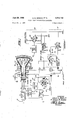
- Fig. ⁇ 1 illustrates, by way of a block and schematic circuit diagram, a color television receiver in accordance with one form of the invention
- Figs. 2(a), 2(b) and 2(c) indicate illustrative index signals generated by the apparatus of Fig. 1 for different conditions of beam tracking;
- Fig. 3 illustrates an additional aspect of the operation of the apparatus of Fig. 1; Y
- Figs. 4(a)-4(c) are views similar to those of Figs. 2(a)-2(c) and illustrative of the operation of another form of the invention;
- Fig. 5 is a block and schematic circuit diagram of apparatus whose operation is illustrated by Fig. 4(a);
- Fig. 6 illustrates another form of the invention.
- An antenna 10 intercepts broadcast signals which may, for example, be of the presently standardized color television variety and which may be viewed as comprising a first carrier wave which is 'amplitude modulated by black and white image information, and a sub-carrier wave which is phaseand amplitude-modulated by information regarding the hue and saturation of the television subject.
- Such signals are applied by the antenna to the receiver section 12 which is represented diagrammatically and which may be understood as containing the usual RF amplifier, converter, IF amplifier and second detector stages.
- the receiver section 12 further includes suitable color translator circuits which provide simultaneous red, green and blue color representative video signals at the output leads 16, 18 and 20.
- Circuitry suitable for deriving simultaneous red, green and blue signals from signals standardized by the Federal Communications Commission on December 19, 1953, may be found, for example, in the book entitled Practical Color Television for the Service Industry, revised edition, April 1954 (second edition, first printing) published by the RCA Service Company, Inc.
- the red, green and blue signals are-applied, respectively, via the leads 16, 18 and 20 to the cathodes 22, 24 and 26 of a color imagereproducing kinescope 28 whose control electrode 30 kis illustrated as connected to a suitable background potential source 32.
- An electrostatic focusing electrode 34 for focusing the electron beams 36, 38 and 40 produced by the cathodes is connected to a suitable positive potential terminal 42.
- a final anode 44 which may be in the form ofv a conductive coating on the interior of the kinescope cone portion is also provided with a'hgh positive operating potential from the terminal 46.
- a conventional electromagnetic deflection yoke 48 comprising horizontal and vertical deflection winding-s is energized with deiiection sawtooth currents of television line and field frequencies from scanning circuits S0 which receive ⁇ synchronizing .Y pulses derived from the received signals in the section 12.
- the color image-reproducing kinescope 28 also includes a target screen 52 which is, by way of illustration, of the horizontal line phosphor strip variety shownmore clearly in the enlarged fragmentary views of Fig.A 2(a) Fig. 2(c). That is, the target screen 52 is made up of a plurality of triads of phosphor strips, horizontally disposed with the strips arranged in the sequence R, G, B, R, G, B.
- the kinescope is additionally provided with an auxiliary deflection coil 54 for producing a high frequency Wobbling of the electron beams, so that the beams are caused to trace a pattern (e.g., sinusoidal) with respect to the phosphor strips of a triad such as those indicated in Fig.
- the beam 36 produced by the cathode 22 is caused to wobble along the path 56 within the red phosphor strip R, while the beams' 38 and v40 wobble along the paths 57 and 58, respectively, ⁇ Withilt the green and blue phosphor -strips G and B.
- the reason for the wobbling of the beams will become apparent hereinafter.
- the coil 54 is energized from a wobble oscillator 59 which provides a color sub-carrier frequency wave (e.g., 3.6 megacycles) through a wobble wave amplifier 60.
- the oscillator 59 may be synchronized with the color sub-carrier wave by means of the color synchronizing bursts which occur during the horizontal blanking intervals of the television signal immediately following the horizontal scanning synchronizing pulses.
- the color information in accordance with present standards is transmitted as phaseand amplitude-modulation of a sub-carrier wave, it is necessary to provide some means for synchronizing the receiver color decoding or translating circuits with the encoding apparatus of the transmitter so that selection of the several color signals may be made.
- the bursts therefore comprise several cycles of sub-carrier wave frequency of fixed phase
- each of the green phosphor strips G is provided with a backing layer 61 of a material capable of emitting ultra-violet light in response to electron impingement.
- a pulse of ultra-violet light energy Will be produced each time the 4beam 38 crosses the ultra-violet light strip 61.
- a photocell 62 receives the ultra-violet light through a window 64 and provides a current in the lead 66 indicative of the traversal of the ultra-violet light strip 61 by the electron beam 38.
- This current is applied via amplifier and llimiter circuits 67 and a phase splitter 68 lto comparator circuits yshown Within the dotted line rectangle 69 which also receive via a phase splitter circuit 70, reference waves bearing a predetermined relation to the wobble energy provided by the oscillator 59.
- the output of the comparator circuits of the described tracking control arrangement comprises a signal in the nature of a correction voltage which, after amplification by a stage 71, is applied to a correction coil 72 for causing the electron beams to berepositioned vertically -to track the color phosphor strips inthe desired manner.
- the correction coil 72 may be a winding of any 'suitable type capable of producing vertical shifting of the positions of the electron beams 36, 3S and 40.
- the pulses 74'4 occur 'atthe rate of 3.6 megacyclestper second 'and arephased differently (i.e.,displaced 180) from the pulses 74' which are produced Vwhen the beam 38 is in its uppermost position.v
- the tracking ⁇ control circuits produce a correction voltage which, when applied to the coil 7-2, results in'upward rrepositioning of lthe Aelectron beams.
- the electron beam "38 serves a ⁇ s-the controlor.fguiding beam, insofar as the tracking function is concerned, and that the other electron beams, by virtue of their being subjected to the correction winding 72), follow lthe .guiding beam.
- InV order to insure, in operation, that'the tracking index signals produced by the ultra-violet strips 61 are actually 'the result of impingem'ent by thekguiding beam 38, and
- That inthe-"signal received and processed by the 'receiv'er section 12 in ⁇ Figure l will include horizontal and vertical blanking pulses of sufficient duration to blank the electron beams 3'6, 38 ⁇ and 40 during the periods of horizontal (line) retrace or H5/back, so that all three ⁇ ofthe'beams rare extinguished during the same period betweenfline scansions.
- -the"following apparatus is provided:
- the multivibrator 78 will be understood, therefore, as being, for example, al monostable typefoperat'iv'e.infsynchronism with the input'pulses ⁇ 76 and may be of the variety'shown -andnescribed in Waveforrns, vo1ufne119 of the MIT r'publication series 'chapter 5 page ⁇ 166.
- Such means are indicated in Figure -1 as including a connection 82 for applying 'positivegoing pulses 84 (corresponding in time and duration to the blanking pulses to the screen grid 86 ofthe wobble amplifier tube 88.
- the ampliier 88 is of 'generally conventional construction, having an anode 90 connected to one end of the 'wobble coil 54, the other end of which is connected to a source of -l-B potential, a control grid 92 to which the 3.6 megacycle wobble Wave is applied from the oscillator 59, a cathode 94 connected tog'round as shown, a grounded suppressor grid 96 and theV screen grid 86.
- the last-mentioned electrode is supplied with a suitable operating potential via a dropping resistor 98 connnected to a source of +B potential, the exact potential applied to the screengrid being selected to afford a nominaldegree of gain.
- the ampli- 'tude ofthe pulses 84 which are applied to the vscreen grid 86 via a capacitor 100 is selected to increase the gain of the tube 88 by a predetermined amount suicient to render the Vamplitude of the wobble path of such size as to traverse substantially the entire triad of the phosphor strips, as shown in Figure 3.
- the primary consideration in determining the factor YT is that Yof providing sufiicient time for the tracking control circuits to 'sense the actual position of the' electron beam 38 and to correct its position before the other two electron beams are rendered'a'ctive at the termination of the blanking pulse 80.
- Opposite phases of the puls'e's produced -by the phototube are thus applied via the capacitors 104 and 106 to the control grids ⁇ 108 and 110, respectively, of comparator tubes 112 and 114 whose cathodes may, as shown, be connected -to ground Vpotential and whose fanodes :11,6 and 1-1'8, respectively, are connected together 'at 'a common load terminal y at the upper end of 1a load iresis'tor 122.
- the suppressor grid 124 of the comparator 112 receives a wave of the same phase and frequency as :that of the wobble wave applied to the coil 54, while the suppressor grid 126 is suppliedwith a Wave of the opposite polarity therefrom (i.fe., wobble phase plus These reference waves are applied to the comparator tubes via the phase splitter V70 which receives 'a version of the ⁇ wobble 'frequency wave from the os'- cillator 59.
- the control grids 108 'and 110 ofthe comparator tubes are connected to :suitable biasv potential terminals through grid-leak lresistors and the common loutput amplifier.
- the amplifier 67 may include an even number of stages, so that the polarity reversal of an amplifier may be disregarded.
- ⁇ Its output signal will, therefore, be understood as being a signal-of the same phase as the current produced by the photocell 62 which, as pointed out supra, is illustrated by the wave forms in Figures 2(11), (b) and (c).
- the amplified and limited photocell signal is applied to the comparator 114 and the opposite phase is applied to the comparator 112, the phase reversal being accomplished in the phase splitter 68.
- the output current pulses of the photocell will comprise the pulses 74' which are of the opposite phase from the wobble wave described by the beam.
- the comparator tubes 112 and 114 are so biased that, normally, the current through the winding 72 is sufiicient to maintain the beam 3S (and the beams 36 and 40) in what may be termed a centered position.
- the input signal to the control grid of the comparator 114 is in phase with the wave applied to the suppressor grid 126, however, that tube will conduct more heavily.
- the tube 112 will conduct more heavily, causing the voltage at the terminal 120 to decrease, thereby lowering the potential of the control grid 130' of the output amplifier 71, with the result that current through the winding 72 is decreased in an amount sufiicient to move the beam- 42 downwardly to its correct position.
- the photocell 62 will produce current pulses 74l ( Figure 2(c)) with the result that the pulses applied to the control grids 108 and 110 of the comparator tubes will be substantially of the opposite polarity from the 3.6 megacycle waves applied to their suppressor grids. Conduction of both of the comparator tubes will, therefore, decrease, causing the potential of the terminal 120 to increase, thereby applying a more positive potential to the control electrode 130' of the The current conduction of the amplifier 71 will thus increase to move the beam 38 upwardly to its proper position.
- the index pulses '74 ( Figure 2(a)) occur at a 7.2 megacycle rate, and with no 3.6 megacycle component, so that the comparator tubes produce no change in the conduction of the -correction amplifier 71.
- the electron beams 36 and 40 commence their active scanning together with the electron beam 38. Moreover, the ampliture of the wobble path described by the beam 38 is reduced to its normal value and, as shown in Figure 3, the three beams'scan simultaneously along the sinusoidal paths 56, 57 and 58, control of the vertical positioning of the beams being maintained by the tracking circuits in response to thev repeated crossing of the ultra-violet strip 61 by the guiding electron beam 38.
- Figures 4(a), 4(b) and 4(c) illustrate the operation of another form of the invention, circuitry for which is shown by the schematic diagram of Figure 5.
- the three electron beams are caused to scan in the wobbling or undulatory fashion described in conneetionwith the first embodiment, respectively, along the paths V56', 57 and 58.withinV the phosphor strips R, G and B.
- the screen of Figure 4(a) includes a pair of index signal-producing elements 61' per triad, which elements are disposed, as shown, one above and one below the green phosphor strip G.
- each television line scansion interval is effectively divided into a brief lock-in period which is followed by the active scanning period.
- the redand blue-designated electron beams are blanked during the lock-in period, the amplitude of the wobble path of the green beam being enlarged as shown by the path 101.
- color television signals are intercepted by an antenna 10 and applied to a receiver section 12 which provides, at its output leads, simultaneous red, green and blue video signals, which signals are applied to the beam intensity controlling electrodes (e.g., cathodes) of a color image reproducing kinescope 28 whose screen is of the type shown in Figure 4(a).
- the kinescope 28' may be substantially identical to the kinescope 28 of Figure 1.
- a deflection yoke 48 associated with the kinescope and supplied with suitable deflection currents from the circuits 50' causes the beams within the kinescope to scan a raster on its screen 52.
- a wobble coil 54' is supplied with alternating current energy of 3.6 megacycles from a wobble oscillator 59' via a wobble amplifier 60', so that the electron beams within the tube are caused to travel along the sinusoidal paths shown in Figure 4(a).
- Ultraviolet light index signal pulses produced by the ultraviolet strips 61 in response to electron impingement are received by a photocell 62 and are applied, after amplification and limiting in circuits 67', to a phase splitter 68. Opposite phases of the index signal are thus provided by the phase splitter 68 to the comparator tubes indicated by the block 69'.
- the comparator tubes are adapted, as in the case of the apparatus of Figure 1, to provide a correction signal to a correction amplifier 71 which, in turn, furnishes a current through the correction coil 72 for repositioning of the electron beams when necessary.
- pulses 84' of suitable duration equal to the length of the lock-in inv terval are applied by a multivibrator 78 to the screen grid of the wobble amplifier 60', just as in the case of the apparatus of Figure l.
- the multivibrator 78' is synchronized by pulses 76' from the scanning deflection circuits 50' and corresponding to. the yback pulses in the latter circuits. Positive blanking pulses are also provided by the multivibrator 78' and are applied to the cathodes of the kinescope 28'.
- the configuration of the screen of Figure 4(a) requires a lshift in the operation of the tracking control circuits between the lock-,inv period and the remainder rof each line scanninginterval.
- the vwave formillustrated below/the screen section shown in Figure 4(a) indicates the fact that an ultra-violet 4light index/signal pulse 140 is produced each time the electron beam traverses one of the ultra-violet light-emitting strips 6 1'.
- the pulses V140 occur at the rate ⁇ of 14.4 megacycles per second.
- a corresponding phase reversal occurs in the error signal for the condition in which the beams are erroneously located above their proper position, as shown in Figure 4(c).
- the guiding ⁇ beam is sufficiently displaced upwardly from its normal position sothat the negative peaks of the wobble pathV strike the lower index-signal producing element 61' of the pair, the resultant indexsignal pulses are as shown at 140".
- the 3.6 megacycle component'present in this signal is as shown by the ⁇ dotted line curve 142", which curve is 180 displaced in g phase from that of the wobble path.
- the index signal pulses 146' When, during the active scanning interval after the termination of the lockin period, the electron beam performing the guiding function Vis erroneously above'its normal position, the index signal pulses 146' have a 3.6 megacycle component 144" which is in phase Iwith the wobble path.
- a wave of 3.6 megacycle energy of wobble phase is applied from the oscillator 59' via a capacitor l164- to the control grid of the switching tube 154 and a 3.6 megalcycle wave of the opposite phase (i.e., wobble phase plus 180) is ⁇ applied to the-control-grid ofthe tube-152 via a capacitor 166.
- the 4control grid of the tube 152 is connected, (through resistors 168vand 170) Yto a bias terminal 172, the potential of which is suilicient to maintain the tube 152 normally in a nonconductive state.
- control grid of the tube 154 is connected through resistors 174 and 176 to a bias terminal 178, the potential of which is sufficient to maintain the't'ube 154 normally conductive.
- a connection 130 between 'the multivibrator 78' and the junction of the resistors y163 and 170 supplies positive-going pulses 84' to the control grid kof the tube 152 for renderingrthat tube conductive during the duration of the pulse.
- These pulses' begin in s ynchronism with the horizontal fly-back pulses 76' and have a duration T1 equal ⁇ to the duration of the lock-in interval.
- Corresponding pulses, but of negative polarity, as shown at 182, are applied via a lead 184 from the multivibrator 78' to the junction of the resistors 174 and 176 for application to the control grid of the switching tube 154.
- the tube 154 is rendered non-conductive.
- the operation of the switching arrangement 156 is as follows:
- the pulses 84' and 182 render the switching tubes 152 and 154
- the tube 152 acts, therefore, as -a'conventional phase splitter ⁇ device and, by virtue of the fact that the signal applied to its control grid is a 3.6 megacycle wave of wobble phase plus 180, the signals applied to the comparator tubes via the leads 160 and 162 will be 3.6 megacycle waves 'of wobble phase and wobble phase plus 180, respectively.
- These reference signal phases may be assumed, for purposes of this explanation, as being the proper phases required for operation of the comparator tubes of the circuitry 69', that is, for comparison with the 'phase of the index signal waves derived by the photocell 62'.
- the ypulses and 182 are terminated, so that the tubes 152 and 154 revert to theirrnormal states, namely, those in which the tube 152 is non-conductive and the tube 154 is conductive. Since the signal applied to the control grid of t-he tube 154 is a wave of wobble phase, the signalsV which are applied to the comparator tubes via the leads and -162 will be waves of the same frequency but, vrespecltively, of wobble phase plus and wobble phase.
- ence waves applied to the comparator tubes are the re- Yverse of those employed during the lock-in period, where? by the stated requirement is met.
- the overal operation of the apparatus of Figure 5 is identical to that described vin connection with the apparatus of Figure 1.
- the present invention provides novel image-reproducing apparatus employinga kinescope of the horizontal line screen variety and means for causing a plurality of electron beams to scan along the screens parallel to the lines thereof but in wobbling fashion.
- Tracking control means responsive to index signals produced by the traversal of index elements by one of the electron beams provide continuous control over the vertical positioning of the beams.
- the duration of the scanning lock-in period is determined or fixed by the time duration of pulses applied to the kinescope cathodes which produce the red and blue electron beams (for blanking purposes) and by corresponding pulses applied to a. gain controlling electrode (e.g., the screen grid) of the wobble ampliiier for increasing the amplitude of the wobble.
- the duration of the lock-in period is established according to those forms of the invention by the setting of the multivibrator device which furnishes the described pulses.
- means are provided for producing a pulse whose leading edge is substantially coincident with the horizontal or line yback pulse and which continues in time until the amplitude of error signal derived from the photocell circuit falls below a preselected threshold value, -at which time the pulse terminates.
- This pulse when applied with suitable polarity to the cathodes of the kinescope which produce the redand blue-designated electron beams and to the gain-controlling electrode of the wobble amplifier, maintains the red and blue beams blanked and increases the amplitude of the wobble path described by the guiding beam.
- the 3.6 megacycle component of the error signal, if any is present, is thus applied via a capacitor 194 to the anode 196 of va rectifier diode 198 which is normally rendered non-conductive by a battery 200, polarized as shown.
- the rectifier 190 is connected -to a bri-stable multivibrator 202 comprising a pair of tubes 204 and 206 connected in the manner indicated.
- the tube 204 of the multivibrator is, by virtue of the connection of its control grid to a point on the resistor voltage divider connected to the +B terminal 207, normally conducting, while the tube 206 is normally in a non-conducting state.
- the anode of the tube 204 rises, therefore, to a positive potential, as shown by the leading edge of the pulse 210, at which time the control grid of the tube 206 is rendered positive, thereby placing that tube in its conductive state.
- the 3.6 megacycle component of the error signal shown by the curve 212, is rectified by the diode 198 to provide at the terminal 214 4a positive potential which is stored in the capacitor 216.
- This positive potential is suiiicient to maintain the tube 206 in its conductive state and the tube 204 in lits non-conductive state.
- the rectier diode 198 will be rendered non-conductive, whereupon the charge on lthe capacitor 216 will leak off at a rate determined by the time constant of the capacitor 216 and resistor 218.
- vthe negative potential of the lbattery 200 is applied to Upon the f 12 'the controlv grid of the tube 206 and is'suicient to render that tube non-conductive.
- the multivibrator then Yreverts to its rst state in which the tube 204 is conductive, so that the potential at the anode of the tube 204 becomes more negative, thereby'dening the trailing edge of the '.pulse 210.r
- the blanking of the red and blue-designated electron beams in the kinevscope ceases andthe increased gain of the Wobble'ampli'- fier is simultaneously removed, so ythat the amplitude of wobble is returned to its normal value.
- the duration of the initial lock-in period of each scanning line Yinterval is determined by the time required for the tracking control circuits to cause the guiding electron beam to become positively locked-in with respect to the index signal-producing element or elements of the kinescope.
- a horizont-al line screen color television system comprising: an image reproducing device including means for causing three electron beams to scan in line-by-line fashion across a target screen including horizontal strips of color-light emitting phosphors and indexing strips, means to modulate said three beams with respective color signals, means to undulate said three electron beams, means to blank all but one of said beams and to increase the amplitude of undulation thereof at the beginning of each line scan to insure interception of an index stripby said one beam, and a tracking circuit means associated with said image reproducing device including means to generate an index signal in response to impingement of an electron beam on said index strips, means to determine the phase of said index signal and means ot correct the vertical position of said beams in response to the phase of said index signal.
- a color television image reproduction system comprising: an image reproducing device including, a target screen made up of a plurality of horizontally oriented elements of different colored light emitting phosphors and trackingindex signal producing elements, and means for producing a plurality of electron beam components; means for causing said plurality of electron beam components to scan across said target screen to produce colored light by beam impingement upon said phosphor elements and to generate index signals by beam impingement upon said index signal producing elements; means for modulating said plurality of electron beam components respectively with different color representative signals; tracking circuit means associated with said image reproducing device and responsive to said generated index signals to shift the positions of said electron beam components relative to said target screen elements; and means for blanking all but one of said electron beam components during an interval of each scansion across said target screen so that, during said blanking interval, only said one electron beam component is effective to generate index signals.
- a color television image reproduction system comprising: an image reproducing device including, a target screen made up of a plurali-ty of horizontally oriented elements of different colored light emitting phosphors and tracking index signal producing elements, and means for producing a plurality of electron beam components; means for causing said plurality of electron beam components to scan across said target screen to produce colored light by beam impingement upon said phosphor elements and to generate index signals by beam impinge ⁇ ment upon said index signal producing elements; means for modulating said plurality of electron beam components respectively with different color representative signals; tracking circuit means associated with said image reproducing device and responsive to said generated index signals to shift the positions of said electron beam components relative to said target screen elements; de-
- a color television image reproduction system comprising: an image reproducing vdeviceincluding, a target screen made .up of a plurality of 'horizontally oriented elements of different colored light emitting phosphors and tracking index signal producing elements, and means lfor producing a plurality of electron beam components; means for causingsaid plurality of electron beam components to scan across said target screen to produce colored lightl by beam impingement upon said phosphor elements and to generate index signals by beam impingement upon said index signal producing elements; means for modulating said plurality of electron beam components respectively with different color representative signals; tracking circuit means associated with said image reproducing device and responsive to said generated index signals to shift the Vpositions of said electron beam components relative to said target screen elements; deflection means to undulate said electron beam components;
- a color television image reproduction system cornprising: an image reproducing device including, a target screen made up of a plurality of horizontally oriented elements of different colored light emitting phosphors and tracking index signal producing elements, and means for producing a plurality of electron beam components; means for causing said plurality of electron beam components to scan across said target screen to produce colored light by beam impingement upon said phosphor elements and to Vgenerate index signals by beam impingement upon said index signal producing elements; means for modulating said plurality of electron beam components respectively with different color representative signals; tracking circuit means associated with said image reproducing device and responsive to said generated index signals to shift the positions of said electron beam com ponents relative to said target screen elements; means for blanking all but one of said electron beam components during an interval of each scansion across said target screen so that, during said blanking interval, only said one electron beam component is effective to generate index signals; and means responsive to said generated tracking signals to terminate said blanking interval only Y when said one electron beam component is in proper position with respect to said index signal producing elements.
- a color television image reproduction system comprising: an image .reproducing device including, a target screen made up of a plurality of horizontally oriented elements of different colored light emitting phosphors and tracking index signal producing elements, and means for producing a plurality of electron beam components; means for causing said plurality of electron beam components to scan across said target screen to produce colored lightV by beam impingement upon said phosphor elements and to generate index signals by beam impingement upon said index signal producing elements; means for modulating said plurality of electron beam components respectively with diierent color representative signals; means to determine the phase of said generated index signals; tracking circuit means associated with said ⁇ image reproducing device and responsive to the phase of said generated index signals to shift the positions of said electron beam components relative to said target screen elements; and means for .blanking fall 'but one :of said electron beam com ⁇ ponents during :an interval .of veach scansion across said target screen. so that, .during said blanking interval, only said one electron beam component is elective to vgenerate
- a color television image reproduction system comprising: an image reproducing device including a target screen made up of a plurality of groups of horizontally oriented elements of different colored light emitting phosphors and a plurality of tracking index signal producing elements associated with each of said groups of phosphor elements in a xed relationship to a particular one of said phosphor elements, and means for producing a plurality of electron beam components; means for causing said plurality of electron beam components to scan across said target screen during a successionl of line intervals to produce colored light by beam impingement upon said phosphor elements and to generate index signals by beam impingement upon said index signal producing elements; means for modulating said plurality of electron beam components respectively with different color representative signals; deection means to undulate said electron beam components; means to increase the amplitude of said electron beam undulation during a por tion of each of said line intervals; means to determine the phase of said generated index signals; tracking circuit means associated with said image reproducing device and responsive to the phase of said generated index signals to control the positions of said electron beam components
- a ⁇ color television image reproduction system comprising: an image reproducing device including a target screen made up of a plurality of groups of horizontally oriented elements of different colored light emitting phosphors and a plurality of tracking index signal producing elements associated with each of said groups of phosphor elements in a xed relationship to a particular one of said phosphor elements, and means for producing a plurality of electron beam components; means for causing said plurality of electron beam components to scan across said target screen during a succession of line intervals to produce colored light by beam impingement upon said phosphor elements and to generate index signals by beam impingement upon said index signal producing elements; means for modulating said plurality "of electron beam components respectively with dilerent color representative signals; deflection means to undulate said electron ybeam components; means to increase the amplitude of said electron beam undulation during a portion of each of said line intervals; means for producing a reference wave having a prescribed relation to said electron beam 15 undulatiom' meansv to determine the phase of' said Sgen#
Description
June 28, 1960 G. B. HERZOG ETAI- 2,943,143
coLoR IMAGEREPRODUCTION APPARATUS Filed Feb. 1, 1955 4 sheets-sheet 1 INVENToRs ESL/E L 50k/v5, .//R 6,5m@ /YE/ezaa June 28, 1960 G. B. HERZOG ETAI- 2,943,143
COLOR IMAGE REPRODUCTION APPARATUS Filed Feb. 1, 1955 4 sheets-sheet 2 MM/M ff- 6,/ @a m 5, G: av. w58 *i554 R 74 camfcr CZ1^ B mtl-5.5L"
1,. i74H I By Z June 28, 1960v G. B. HERZOG EVAL 2,943,143
coLoR IMAGE REPRODUCTION APPARATUS Filed Feb. l, 1955 4 Sheets-Sheet 3 l Z INVENToRs B* I MC2/'im June 28, 1960 G. B. HERZOG EVAL 2,943,143
coLoP IMAGE REPRODUCTION APPARATUS 3.6M- Waaf d,
l0 fzj I 'l m IN VEN TORS 5a/f L. 9x/Ms, Je s' 65mm b2c/206 9 Claims. v(Cl. 178-S.4) f
The vpresent invention -relates to new and improved television image reproduction apparatus and, particularly, to y apparatus of the type employing a cathode ray .tube of the so-called horizontal line screen variety.
Among the yforms of color television image reproducing apparatus proposed thus far is one which includes a cathode ray kinescope having a'target screen made up of a plurality of groups of strip-like elements adapted to emit light of respectively diierent colors in response to electron beam impingement. In they case of such a tube, means-are provided for causing a plurality of electron bea-m components to scan a raster pattern on the screen, the raster comprising a plurality of horizontal line scans separated from, each other vertically but being in the direction Vparallel to the groups of stiip-likeelements. Means are provided additionally, as a practical matter, to insure tracking of the groups of color elements by the electron beam componentsin an orderly sequence so that the video signals representative of the vrespectively different component colors of the image being televised are actually employed in controlling the intensity of the beam component' intended to illuminate a given color-product ing element. Such means, which may be considered as partaking of the 4nature of. a servo mechanism, employ, for example, special elements (e.g ultra-violet light-emit ting material) associated lwith the target screen for sensing the vertical positionk of the beam components and for providing indications thereof and means responsive to :such indications `for correcting the vertical position of the beam components with respect to the screen. y
Arrangements are known in which a single electron beam is caused to wobble or undulate vertically in its horizontal travel during a television line scan so that t-he beam successively impinges upon phosphor strips of different color characteristics and video signals respectively representative of suchrcolors are applied successively to Ithe beam intensity controlling electrode in the proper sequence. One proposal for insuring that the electron beam in such a tube tracks a given group of phosphor strips provides for-a stripv of material .such as utltra-violet light-emittingphosphor which is .disposed along each color phosphor of a given color, so that as the beam crosses the ultra-violet phosphor strip an index- A ing signal is produced which may be compared with a standard ffor the purpose of determining the propriety of the beams position.
Where it is desiredto employ 1a lplurality of electron beams inV Iahorizontal line screen color lcinescope, the tracking problem lis rendered `more difl'icult.l y
Itis aprimary object o f the present invention toptovide novel meansV -for causinga -plurality of electron beams to track along predetermined horizontal paths in a horizontal vline screen kinescope. v
Another object `of the vinvention is the Vprevisioni -oi means Stor insuring, vin a simple A.but ,effective the tracking of predetermined paths in. -a horizontal line screen color kinescope by a `pluralitylof `electrony beams,
of `aselected component color characteristic. l
In general, the present invention provides novel :color image reproducing apparatus which includes a cathode ray `tube having a screenrnade 11p Q a'plurality of groups of horizontally oriented strip-like elementsV (e.g.,*phos phor strips) of respectively diierent light-,emittingcharacteristics and means for causing a pluralityof electron beams to scan across 'the screen, each beam being caused further to wobblein its travel. The Vtarget ,screen also includes index signal-producing elements (eg, ultraviolet light-emitting phosphor) whicmin,response` to electron impinge-ment, generate signals indicative of beam position. In order to insure that the index signals thus generated are the `result of the travel of a particularv one of the beams -(i.e., the control beam), means are, additionally provided lfor blanking all but that electron beam during the Virst part of each line scanrsion. Thus, each line scan-may be viewed as comprising a rst, relatively short interval in which lock-in of the control beam is accomplished, followed by the useful portion of thescan during which none of the beams is blanked and in which image `reproduction is effected by the severalibeams.
In accordance withl a irst illustrative,embodimentV of the invention, three such beams are provided and. Vare caused .to scan across a screen made 'up of a plurality of triads of respectively diiferent,=horizontally oriented `color strip-like elements, one selected elementof -each triad being provided with a tracking index signal-producing ele,-
, lfcally Vdisposed 'with respect to one of thestriplike color elements -of a triad, so that the electron beam which is intended -to illuminate that color normally v,describes a sinusoidal wobble path whose positive and negative peaks are limited by the index elements of a pair. That is, the beam may be said to ride .betweentheindex elements of a pair. Tracking circuit means are provided for comparing the resultant index signals with the reference to produce a correction signal. During the rst part of each Yline scan, however, (i.e., during the lock-in Priod), the amplitude of wobble `impar-ted to the con- Ytrol beam is substantially enlarged, so that the positive and negative peaks of vthe sinusoidal path described by the control beam lie onnopposite sides ofthe pair jof index elements. Tp accommodate the different 4phasing of vthe index Isignalsgthus produced during -thelock-in period, means areprovided for shifting the reference wave which is appliedgtothe tracking circuit .means during that Vinteryal.A
. further l`illustrativeform ofthe :invention is generally applicable to both of the above-described forms in that in accQldanCe therewith, means rare provided .for dening the .period in which all of the beams except the vguiding beam lareblanked as the period beginning at the 'com'- mencernentvof a line scanning interval and .ending when that `beam is vproperly locked in, -as determined by the tracking ,control apparatus.
As will be appreciated, `the present invention 'affords the advantages of increased llight output over that normallyv available with single breampkinescopesof the'linescreen variety `and a simpliiicationof `the vapparatus required for applying the-color representative video signals to the 'kinessepe t Additional objects and advantages of the present invention will become apparent to those skilled in the art from a study of the following detailed description of the following accompanying drawing in which: Y i
Fig. `1 illustrates, by way of a block and schematic circuit diagram, a color television receiver in accordance with one form of the invention;
Figs. 2(a), 2(b) and 2(c) indicate illustrative index signals generated by the apparatus of Fig. 1 for different conditions of beam tracking;
Fig. 3 illustrates an additional aspect of the operation of the apparatus of Fig. 1; Y
Figs. 4(a)-4(c) are views similar to those of Figs. 2(a)-2(c) and illustrative of the operation of another form of the invention;
Fig. 5 is a block and schematic circuit diagram of apparatus whose operation is illustrated by Fig. 4(a); and
Fig. 6 illustrates another form of the invention.
Referring to the drawing and, particularly, to Fig. 1 thereof, there is shown an illustrative color television receiver which may be of any suitable type. An antenna 10 intercepts broadcast signals which may, for example, be of the presently standardized color television variety and which may be viewed as comprising a first carrier wave which is 'amplitude modulated by black and white image information, and a sub-carrier wave which is phaseand amplitude-modulated by information regarding the hue and saturation of the television subject.
Such signals are applied by the antenna to the receiver section 12 which is represented diagrammatically and which may be understood as containing the usual RF amplifier, converter, IF amplifier and second detector stages. The receiver section 12 further includes suitable color translator circuits which provide simultaneous red, green and blue color representative video signals at the output leads 16, 18 and 20.
Circuitry suitable for deriving simultaneous red, green and blue signals from signals standardized by the Federal Communications Commission on December 19, 1953, may be found, for example, in the book entitled Practical Color Television for the Service Industry, revised edition, April 1954 (second edition, first printing) published by the RCA Service Company, Inc. The red, green and blue signals are-applied, respectively, via the leads 16, 18 and 20 to the cathodes 22, 24 and 26 of a color imagereproducing kinescope 28 whose control electrode 30 kis illustrated as connected to a suitable background potential source 32. An electrostatic focusing electrode 34 for focusing the electron beams 36, 38 and 40 produced by the cathodes is connected to a suitable positive potential terminal 42. A final anode 44, which may be in the form ofv a conductive coating on the interior of the kinescope cone portion is also provided with a'hgh positive operating potential from the terminal 46. A conventional electromagnetic deflection yoke 48 comprising horizontal and vertical deflection winding-s is energized with deiiection sawtooth currents of television line and field frequencies from scanning circuits S0 which receive `synchronizing .Y pulses derived from the received signals in the section 12.
The color image-reproducing kinescope 28 also includes a target screen 52 which is, by way of illustration, of the horizontal line phosphor strip variety shownmore clearly in the enlarged fragmentary views of Fig.A 2(a) Fig. 2(c). That is, the target screen 52 is made up of a plurality of triads of phosphor strips, horizontally disposed with the strips arranged in the sequence R, G, B, R, G, B. The kinescope is additionally provided with an auxiliary deflection coil 54 for producing a high frequency Wobbling of the electron beams, so that the beams are caused to trace a pattern (e.g., sinusoidal) with respect to the phosphor strips of a triad such as those indicated in Fig. 2(a), for example, bythe lines 56, 57 and'58. Stated otherwise, the beam 36 produced by the cathode 22 is caused to wobble along the path 56 within the red phosphor strip R, while the beams' 38 and v40 wobble along the paths 57 and 58, respectively, `Withilt the green and blue phosphor -strips G and B. The reason for the wobbling of the beams will become apparent hereinafter. At this point, however, it may be noted, by way of example, that the coil 54 is energized from a wobble oscillator 59 which provides a color sub-carrier frequency wave (e.g., 3.6 megacycles) through a wobble wave amplifier 60. The oscillator 59 may be synchronized with the color sub-carrier wave by means of the color synchronizing bursts which occur during the horizontal blanking intervals of the television signal immediately following the horizontal scanning synchronizing pulses. Reference may be made to an article entitled The NTSC Color-TV synchronizing Signal which appeared in the February 1952 issue of-Electronics (McGraw-Hill Publishing Company, Inc.) for a detailed description of color synchronizing bursts. While it does not constitute a part of the present invention, it may be noted briefly that, since the color information in accordance with present standards is transmitted as phaseand amplitude-modulation of a sub-carrier wave, it is necessary to provide some means for synchronizing the receiver color decoding or translating circuits with the encoding apparatus of the transmitter so that selection of the several color signals may be made. The bursts therefore comprise several cycles of sub-carrier wave frequency of fixed phase,
whereby to provide a reference phase for the color translating sections of the receiver.
As thus far described, therefore, it will be understood that, in the apparatus of Fig. 1, video signals respectively representative of the red, green and blue content of a television subject are employed in modulating the intensity of the electron beams 36, 38 and 40 which are adapted to scan along the red, green, and blue light-emitting phosphor strips R, G and B. As hasl been stated, color image reproducing arrangements'of the horizontal line screen varietyA normally require means for insuring that kelectron beams Within the kinescope properly track the correct phosphor lstr ips. In accordance with one form oftracking arrangement as illustrated in Fig. 1, each of the green phosphor strips G is provided with a backing layer 61 of a material capable of emitting ultra-violet light in response to electron impingement. By virtue of the sinusoidal path 57 followed by the electron beam 38 as it scans along the green phosphor strip G, a pulse of ultra-violet light energy Will be produced each time the 4beam 38 crosses the ultra-violet light strip 61. A photocell 62 receives the ultra-violet light through a window 64 and provides a current in the lead 66 indicative of the traversal of the ultra-violet light strip 61 by the electron beam 38. This current is applied via amplifier and llimiter circuits 67 and a phase splitter 68 lto comparator circuits yshown Within the dotted line rectangle 69 which also receive via a phase splitter circuit 70, reference waves bearing a predetermined relation to the wobble energy provided by the oscillator 59. The output of the comparator circuits of the described tracking control arrangement comprises a signal in the nature of a correction voltage which, after amplification by a stage 71, is applied to a correction coil 72 for causing the electron beams to berepositioned vertically -to track the color phosphor strips inthe desired manner. The correction coil 72 may be a winding of any 'suitable type capable of producing vertical shifting of the positions of the electron beams 36, 3S and 40. i y i vThe general operation ofthe arrangement outlined thus far in connection with Figure 1 will be described briey. As will be seen fromY Figure 2(a) the electron beam spot 38 travels along the sinusoidal' path 57 and, when properly tracking, crosses the ultra-violet index strip 61 of a -given triad twice during each wobble cycle. lThe output signal of the phototube 62, therefore, will comprise, during-proper tracking, a series of -pulses 74 which are equally spaced in time and which occur at twice the wob- 'ble frequency, or at the rate of 7.2 megacycles'per second. When the electron beam 38 is erroneously shifted upwardly'to an extreme positionso 4that the negatve? 'peaks of the sine wave-57h11 on the ultra-violet strip 61 (as shown' in Figure 2(b)) thetracking index signals will the sinewave 57 strike theultra-violet light-emitting index strip `61'- (as in Figure' 2(0)) the'V pulses from the phototube 62 will -be as indicated by the pulses 74". The pulses 74'4 occur 'atthe rate of 3.6 megacyclestper second 'and arephased differently (i.e.,displaced 180) from the pulses 74' which are produced Vwhen the beam 38 is in its uppermost position.v In response to the pulses 7 the tracking `control circuits produce a correction voltage which, when applied to the coil 7-2, results in'upward rrepositioning of lthe Aelectron beams. v
AvrzFrom the'foregoing, `itwill be appreciated that, in accordance-Awith thepresent invention, the electron beam "38 serves a`s-the controlor.fguiding beam, insofar as the tracking function is concerned, and that the other electron beams, by virtue of their being subjected to the correction winding 72), follow lthe .guiding beam. InV order to insure, in operation, that'the tracking index signals produced by the ultra-violet strips 61 are actually 'the result of impingem'ent by thekguiding beam 38, and
`not by one of the other beams 36 and 40, means are o provided, yas has been stated, `for' blanking the Vbeams other than `the guiding lbeam 38 during vthe first portion of each line scanning interval. A's is understood by those skilled in the art, 4broadcast television signals are a composite of image information-"and scanning synchroniza- .tion information, signals `representative lof the latterb'eing :transmitted as pulses ofthe requisite-repetition rate superimposed upon beam-blankingpulses of specified dur-ation. That inthe-"signal received and processed by the 'receiv'er section 12 in `Figure l will include horizontal and vertical blanking pulses of sufficient duration to blank the electron beams 3'6, 38 `and 40 during the periods of horizontal (line) retrace or H5/back, so that all three `ofthe'beams rare extinguished during the same period betweenfline scansions. In order to carry out the additional bl'anking of the beams '36 and 40 during the preliminary or 'lock-'in period of each line lscanning interval, -the"following apparatus is provided:
1 Pulses 76 corresponding tothe horizontal ilyback; pulses 'normally produced in the deiiection'circuits 50 vare de- -rived from those circuits and 'applied `to a multivibrator l78 'which' may be of any suitable variety capable of providing output' pulses 280 occurring at television line scanning irate and of a duration "suiiicient to encompass a selected portion of a scanning line interval. The multivibrator 78 -will be understood, therefore, as being, for example, al monostable typefoperat'iv'e.infsynchronism with the input'pulses `76 and may be of the variety'shown -andnescribed in Waveforrns, vo1ufne119 of the MIT r'publication series 'chapter 5 page `166. Positive output pulses 8i) "from the `rnulti'vibr-ator Jare applied tothe cathodes 22 andv 26 of the `kinescope '23 to blank the beams 36' and 40 4for a predeterminedperiod following the commencement 'of ea'chline scanning interval. Thus, 'during that interval, only 'the green electron beam 38 (the guidn'g beam) will be -on, so that thevultra-violet light index pulses produced in lthe photocell 62 and `tracking circuits will necessarily be the result of impingement of lthe index element yby that beam as 'it wobbles vsinusoidally Jvalon-gthe 'path 57.-L 'i saine' `position-correcting action (i.e.,y as produced by the 130 .In order to 'render the action of the 4tracking control circuits veven more positive during the preliminary or lock-in period of each line 'scanning interval, means are additionally provided in accordance with the invention for increasing the amplitude of the wobble 'path traversed by the guiding beam. Such means are indicated in Figure -1 as including a connection 82 for applying 'positivegoing pulses 84 (corresponding in time and duration to the blanking pulses to the screen grid 86 ofthe wobble amplifier tube 88. The ampliier 88 is of 'generally conventional construction, having an anode 90 connected to one end of the 'wobble coil 54, the other end of which is connected to a source of -l-B potential, a control grid 92 to which the 3.6 megacycle wobble Wave is applied from the oscillator 59, a cathode 94 connected tog'round as shown, a grounded suppressor grid 96 and theV screen grid 86. The last-mentioned electrode is supplied with a suitable operating potential via a dropping resistor 98 connnected to a source of +B potential, the exact potential applied to the screengrid being selected to afford a nominaldegree of gain. The ampli- 'tude ofthe pulses 84 which are applied to the vscreen grid 86 via a capacitor 100 is selected to increase the gain of the tube 88 by a predetermined amount suicient to render the Vamplitude of the wobble path of such size as to traverse substantially the entire triad of the phosphor strips, as shown in Figure 3. In Figure 3, therefore, it will be seen that during the period T which includes the first portion of a line scanning interval, the electron beams 36 and 40 are extinguished, as described above, by the pulses 80 and that the wobble path 101 described by the beam 38 is of substantially greater ampli'- tude in the vertical direction than that of the path 57 de- 'scribed during the active scanning portionof the line interval. The pulse 84 employed in increasing the amplitude of wobble is shown in Figure 3 as having vthe same time duration T as the pulse 80. The exact duration ofthe lock-in period v(i.`e., the duration T) may be s elected to be any relatively short period compared with the line scanning period, such, vfor example, as 5 percent thereof. The primary consideration in determining the factor YT is that Yof providing sufiicient time for the tracking control circuits to 'sense the actual position of the' electron beam 38 and to correct its position before the other two electron beams are rendered'a'ctive at the termination of the blanking pulse 80.
While the operation of the apparatus of Figure 1 has been described in general terms,a specific, illustrative tracking control arrangement, as shown in the drawing, will now be explained in greater detail. During the lockin period T, the electron beams 36 and 40 are extinguished by the blanking pulse 80, and current pulses from the phototube 62, such asthose shown in Figures 2(7a), 2(b) and 2(b) and resulting `from the traversal of the ultra-violet light-emitting strip 61 by the beam 38, are applied via the amplifier 'and limiter circuits 6'7 to the control grid V102 of the phase splitter "68. Opposite phases of the puls'e's produced -by the phototube are thus applied via the capacitors 104 and 106 to the control grids `108 and 110, respectively, of comparator tubes 112 and 114 whose cathodes may, as shown, be connected -to ground Vpotential and whose fanodes :11,6 and 1-1'8, respectively, are connected together 'at 'a common load terminal y at the upper end of 1a load iresis'tor 122. "The suppressor grid 124 of the comparator 112 receives a wave of the same phase and frequency as :that of the wobble wave applied to the coil 54, while the suppressor grid 126 is suppliedwith a Wave of the opposite polarity therefrom (i.fe., wobble phase plus These reference waves are applied to the comparator tubes via the phase splitter V70 which receives 'a version of the `wobble 'frequency wave from the os'- cillator 59. The control grids 108 'and 110 ofthe comparator tubes are connected to :suitable biasv potential terminals through grid-leak lresistors and the common loutput amplifier.
load 'terminal 120 'of the comparators` is connected via a coupling capacitor 128 to the control electrode of the output amplifier 71 which is of conventional form and which includes the beam position correction winding 72 in the load circuit of its anode 130.
Assuming that the winding 72 is so oriented with respect to the kinescope 28 that increased current through the winding moves the electron beams upwardly while decreased current moves the beams downwardly, the operation of the circuit of Figure 3V will be as follows:
The amplifier 67 may include an even number of stages, so that the polarity reversal of an amplifier may be disregarded. `Its output signal will, therefore, be understood as being a signal-of the same phase as the current produced by the photocell 62 which, as pointed out supra, is illustrated by the wave forms in Figures 2(11), (b) and (c). The amplified and limited photocell signal is applied to the comparator 114 and the opposite phase is applied to the comparator 112, the phase reversal being accomplished in the phase splitter 68. Assuming that the beam 38 is erroneously high (as shown in Figure 2(b) so that negative peaks of the wobble wave occur at the ultra-violet index strip 61, the output current pulses of the photocell will comprise the pulses 74' which are of the opposite phase from the wobble wave described by the beam. The comparator tubes 112 and 114 are so biased that, normally, the current through the winding 72 is sufiicient to maintain the beam 3S (and the beams 36 and 40) in what may be termed a centered position. When the input signal to the control grid of the comparator 114 is in phase with the wave applied to the suppressor grid 126, however, that tube will conduct more heavily. Similarly, the tube 112 will conduct more heavily, causing the voltage at the terminal 120 to decrease, thereby lowering the potential of the control grid 130' of the output amplifier 71, with the result that current through the winding 72 is decreased in an amount sufiicient to move the beam- 42 downwardly to its correct position.
Conversely, if the beam erroneously moves downwardly in the scanning process, the photocell 62 will produce current pulses 74l (Figure 2(c)) with the result that the pulses applied to the control grids 108 and 110 of the comparator tubes will be substantially of the opposite polarity from the 3.6 megacycle waves applied to their suppressor grids. Conduction of both of the comparator tubes will, therefore, decrease, causing the potential of the terminal 120 to increase, thereby applying a more positive potential to the control electrode 130' of the The current conduction of the amplifier 71 will thus increase to move the beam 38 upwardly to its proper position.
When the electron beam 38 is properly centered with respect to the ultra-violet, light-emitting index strip 61, the index pulses '74 (Figure 2(a)) occur at a 7.2 megacycle rate, and with no 3.6 megacycle component, so that the comparator tubes produce no change in the conduction of the -correction amplifier 71.
At the end of the lock-in period T,,the electron beams 36 and 40 commence their active scanning together with the electron beam 38. Moreover, the ampliture of the wobble path described by the beam 38 is reduced to its normal value and, as shown in Figure 3, the three beams'scan simultaneously along the sinusoidal paths 56, 57 and 58, control of the vertical positioning of the beams being maintained by the tracking circuits in response to thev repeated crossing of the ultra-violet strip 61 by the guiding electron beam 38.
Figures 4(a), 4(b) and 4(c) illustrate the operation of another form of the invention, circuitry for which is shown by the schematic diagram of Figure 5. In'accordance with this form of the invention and as i-sA shown in Figure 4(a), the three electron beams are caused to scan in the wobbling or undulatory fashion described in conneetionwith the first embodiment, respectively, along the paths V56', 57 and 58.withinV the phosphor strips R, G and B. As opposed in the screen arrangementy of Figure 2(a), however, the screen of Figure 4(a) includes a pair of index signal-producing elements 61' per triad, which elements are disposed, as shown, one above and one below the green phosphor strip G. Normally, therefore, and when the beams are properly tracking, the limits of vertical movement of the green designated electron beam are fixed by the strips 61' and the redand blue-designated beams follow their paths, as indicated. Again, as in the case of the apparatus of Figures 1 through 3, each television line scansion interval is effectively divided into a brief lock-in period which is followed by the active scanning period. Also, the redand blue-designated electron beams are blanked during the lock-in period, the amplitude of the wobble path of the green beam being enlarged as shown by the path 101. By virtue of the arrangement of the ultra-violet strips in the screen of Figure 4(a) as .distinguished from the disposition of the corresponding strip in the screen of Figure 2(a), however, a different arrangement for the tracking control circuit means is afforded in connection with the screen of Figure 4(a) 4so that the proper type of response may be had during both the locked-in period and the active scanning period of a line. This aspect of the invention will be more fully understood from the following description of the apparatus of Figure 5 in which those elements which may be identical to corresponding elements of Figure 1 are represented by blocks bearing the same reference numerals with the prime notation.
In Figure 5, color television signals are intercepted by an antenna 10 and applied to a receiver section 12 which provides, at its output leads, simultaneous red, green and blue video signals, which signals are applied to the beam intensity controlling electrodes (e.g., cathodes) of a color image reproducing kinescope 28 whose screen is of the type shown in Figure 4(a). It will be understood, however, that, aside from the screen, the kinescope 28' may be substantially identical to the kinescope 28 of Figure 1. A deflection yoke 48 associated with the kinescope and supplied with suitable deflection currents from the circuits 50' causes the beams within the kinescope to scan a raster on its screen 52. A wobble coil 54' is supplied with alternating current energy of 3.6 megacycles from a wobble oscillator 59' via a wobble amplifier 60', so that the electron beams within the tube are caused to travel along the sinusoidal paths shown in Figure 4(a). Ultraviolet light index signal pulses produced by the ultraviolet strips 61 in response to electron impingement are received by a photocell 62 and are applied, after amplification and limiting in circuits 67', to a phase splitter 68. Opposite phases of the index signal are thus provided by the phase splitter 68 to the comparator tubes indicated by the block 69'. The comparator tubes are adapted, as in the case of the apparatus of Figure 1, to provide a correction signal to a correction amplifier 71 which, in turn, furnishes a current through the correction coil 72 for repositioning of the electron beams when necessary.
In order to increase the amplitude of wobble of the guiding beam within the kinescope (i.e., the beam adapted to scan along the green phosphor strips G), pulses 84' of suitable duration equal to the length of the lock-in inv terval are applied by a multivibrator 78 to the screen grid of the wobble amplifier 60', just as in the case of the apparatus of Figure l. The multivibrator 78' is synchronized by pulses 76' from the scanning deflection circuits 50' and corresponding to. the yback pulses in the latter circuits. Positive blanking pulses are also provided by the multivibrator 78' and are applied to the cathodes of the kinescope 28'.
As hasA been stated, the configuration of the screen of Figure 4(a) requires a lshift in the operation of the tracking control circuits between the lock-,inv period and the remainder rof each line scanninginterval. The reason for such shift'will be apparentfrom a consideration `of Figures 4(a), -4(b) and 4(0). The vwave formillustrated below/the screen section shown in Figure 4(a) indicates the fact that an ultra-violet 4light index/signal pulse 140 is produced each time the electron beam traverses one of the ultra-violet light-emitting strips 6 1'. During the lockin period, that is, during the interval T1, the pulses V140 occur at the rate `of 14.4 megacycles per second. By virtue of the unequal spacing of the pulses, however, there is present a comparatively large component of 7.2 megacycleienergy as Vshown by the dotted line curve 142. The corresponding 7.2-megacycle component which is present after the lock-inv period has ended, that is, during the active scanning interval,` and as shown by the dotted linecurve 144, is shifted in phase from that of the component 142. This shift in phase results from the fact that, during the lock-in period, the sinusoidal path traverses the ultra-violet light strips between the peaks of the sine wave, while, during the remainder of the line interval, the ultra-violet light signal pulses are produced bythe peaks of the sine wave. It will thus be apparent that a shift in the operation of the phase comparator circuits of the tracking control arrangement is necessitated. The actual yshift required will be better understood from i the showings of Figures 4(b`) and 4(0) which are illus- Atratve Aof the conditionsfexisting when the beams are erroneously positioned below and above, respectively,
`their proper positions.
' In `the extreme condition of Figure 4(b) in which the `positive peaks of the sinusoidal path strikethe upper one of the index strips 61', the resultant index signal pulses Will be as shown by the pulses 140". By reason of the unequal spacing in time of these pulses, there is present a 3.6 megacycle'component shown by the dotted line curve 142. This curve is, as may be seen, in phase with the wobble path described by the guiding electron beam. If the guiding beam remains in an erroneously `low position after the llock-in period has terminated and after the amplitude of wobble has been decreased to its normal size, the resultant index signal 'pulses will occur in time as shown vby the pulses 146. These pulses are unequally spaced in time so that there is present a 3.6 megacycle component shown by the dotted line curve 144', the phase of which is 180 displaced from the phase of the wobble path described by the beam. It will thus be understood that, while the error is in the same direction in both parts of the showing of Figure 4(b) namely, downward, the phase of the error signal produced in the photocell circuit is reversed.
A corresponding phase reversal occurs in the error signal for the condition in which the beams are erroneously located above their proper position, as shown in Figure 4(c). The guiding` beam is sufficiently displaced upwardly from its normal position sothat the negative peaks of the wobble pathV strike the lower index-signal producing element 61' of the pair, the resultant indexsignal pulses are as shown at 140". The 3.6 megacycle component'present in this signal is as shown by the `dotted line curve 142", which curve is 180 displaced in g phase from that of the wobble path. When, during the active scanning interval after the termination of the lockin period, the electron beam performing the guiding function Vis erroneously above'its normal position, the index signal pulses 146' have a 3.6 megacycle component 144" which is in phase Iwith the wobble path.
By reason of the foregoing, means are provided in the apparatus of Figure v5 for reversing the sense of operation of the tracking control circuit between the two conditions of operation (i.e., Vthelock-in operation and the active scanning operation). This apparatus is indicated schematically within the dotted line rectangle 150 which will be understood as comprising a switching arrangement operative to apply different phases of the reference wave from theoscillator :59' to the comparator tube circuitry 69. The switching arrangement 150 'comprises, `by way of example, a pair of tubes 152 and 154,
. respectively, conductive and non-conductive.
Y Thus,` it will be vunderstood that the phases of the refereach having a cathode, a control `grid and an anode. The cathodes of the tubes 152 and 154 are connected to a suitable reference potential (e.'g., ground) through a common resistor 156, while the anodes ofthe tubes are connected to a source of +B operating potential through a single resistor 153. A signal lead v161i connects the Vanodes of the switching tubes to the suppressor grid of one of the comparator tubes in the `box 6'9',`while a signal llead 162 connects the cathodes of the switching tubes to theV suppressor grid of the other comparator tube. A wave of 3.6 megacycle energy of wobble phase is applied from the oscillator 59' via a capacitor l164- to the control grid of the switching tube 154 and a 3.6 megalcycle wave of the opposite phase (i.e., wobble phase plus 180) is` applied to the-control-grid ofthe tube-152 via a capacitor 166. The 4control grid of the tube 152 is connected, (through resistors 168vand 170) Yto a bias terminal 172, the potential of which is suilicient to maintain the tube 152 normally in a nonconductive state. Similarly, the control grid of the tube 154 is connected through resistors 174 and 176 to a bias terminal 178, the potential of which is sufficient to maintain the't'ube 154 normally conductive. A connection 130 between 'the multivibrator 78' and the junction of the resistors y163 and 170 supplies positive-going pulses 84' to the control grid kof the tube 152 for renderingrthat tube conductive during the duration of the pulse. These pulses', as explained supra, begin in s ynchronism with the horizontal fly-back pulses 76' and have a duration T1 equal `to the duration of the lock-in interval. Corresponding pulses, but of negative polarity, as shown at 182, are applied via a lead 184 from the multivibrator 78' to the junction of the resistors 174 and 176 for application to the control grid of the switching tube 154. For the duration of the `pulse 182, the tube 154 is rendered non-conductive.
The operation of the switching arrangement 156 is as follows:
During the lock-in period (T1 in Figure 4) the pulses 84' and 182 render the switching tubes 152 and 154, The tube 152 acts, therefore, as -a'conventional phase splitter `device and, by virtue of the fact that the signal applied to its control grid is a 3.6 megacycle wave of wobble phase plus 180, the signals applied to the comparator tubes via the leads 160 and 162 will be 3.6 megacycle waves 'of wobble phase and wobble phase plus 180, respectively. These reference signal phases may be assumed, for purposes of this explanation, as being the proper phases required for operation of the comparator tubes of the circuitry 69', that is, for comparison with the 'phase of the index signal waves derived by the photocell 62'. At the end of the lock-in period T1, the ypulses and 182 are terminated, so that the tubes 152 and 154 revert to theirrnormal states, namely, those in which the tube 152 is non-conductive and the tube 154 is conductive. Since the signal applied to the control grid of t-he tube 154 is a wave of wobble phase, the signalsV which are applied to the comparator tubes via the leads and -162 will be waves of the same frequency but, vrespecltively, of wobble phase plus and wobble phase.
ence waves applied to the comparator tubes are the re- Yverse of those employed during the lock-in period, where? by the stated requirement is met. Aside from the phase reversal ofthe reference waves applied to the comparator tubes of the tracking control arrangement, the overal operation of the apparatus of Figure 5 is identical to that described vin connection with the apparatus of Figure 1.
From the foregoing, it will be appreciated that the present invention, as described thus far, provides novel image-reproducing apparatus employinga kinescope of the horizontal line screen variety and means for causing a plurality of electron beams to scan along the screens parallel to the lines thereof but in wobbling fashion. Tracking control means responsive to index signals produced by the traversal of index elements by one of the electron beams provide continuous control over the vertical positioning of the beams.
In the apparatus of Figure 5, as in the case of Figure 1, the duration of the scanning lock-in period is determined or fixed by the time duration of pulses applied to the kinescope cathodes which produce the red and blue electron beams (for blanking purposes) and by corresponding pulses applied to a. gain controlling electrode (e.g., the screen grid) of the wobble ampliiier for increasing the amplitude of the wobble. In other words, the duration of the lock-in period is established according to those forms of the invention by the setting of the multivibrator device which furnishes the described pulses. According to another form of the invention which is illustrated in Figure 6, means are provided for rendering the duration of the lock-in period flexible, that the lock-in period may continue until the guiding beam is actual-ly locked in with its index signal-producing element or elements. T-hat is to say, the circuitry of Figure 6 may be substituted, if desired, for the monostable multivibrator of Figures l and 5.
In the arrangement of Figure 6, means are provided for producing a pulse whose leading edge is substantially coincident with the horizontal or line yback pulse and which continues in time until the amplitude of error signal derived from the photocell circuit falls below a preselected threshold value, -at which time the pulse terminates. This pulse, when applied with suitable polarity to the cathodes of the kinescope which produce the redand blue-designated electron beams and to the gain-controlling electrode of the wobble amplifier, maintains the red and blue beams blanked and increases the amplitude of the wobble path described by the guiding beam. Amplified index signal pulses produced in the photocell of the tracking control arrangement lin response to electron impingement upon the index-producing element or elements `are applied, after amplification and limiting, to the control grid of `an amplifier 190 which, in turn, applies the amplified pulses to the input of a bandpass filter 192 having a passband of 3 to 4 megacycles. The 3.6 megacycle component of the error signal, if any is present, is thus applied via a capacitor 194 to the anode 196 of va rectifier diode 198 which is normally rendered non-conductive by a battery 200, polarized as shown. The rectifier 190 is connected -to a bri-stable multivibrator 202 comprising a pair of tubes 204 and 206 connected in the manner indicated. The tube 204 of the multivibrator is, by virtue of the connection of its control grid to a point on the resistor voltage divider connected to the +B terminal 207, normally conducting, while the tube 206 is normally in a non-conducting state. application to the control grid of the tube 204 of a negative-going horizontal iiyback pulse 208 derived in the dellection circuits of the receiver, that tube is out off. The anode of the tube 204 rises, therefore, to a positive potential, as shown by the leading edge of the pulse 210, at which time the control grid of the tube 206 is rendered positive, thereby placing that tube in its conductive state.
The 3.6 megacycle component of the error signal, shown by the curve 212, is rectified by the diode 198 to provide at the terminal 214 4a positive potential which is stored in the capacitor 216. This positive potential is suiiicient to maintain the tube 206 in its conductive state and the tube 204 in lits non-conductive state. When the amplitude of the 3.6 megacyle component of error signal decreases Ibelow a value determined by the potential of the battery 200, the rectier diode 198 will be rendered non-conductive, whereupon the charge on lthe capacitor 216 will leak off at a rate determined by the time constant of the capacitor 216 and resistor 218. At this time, vthe negative potential of the lbattery 200 is applied to Upon the f 12 'the controlv grid of the tube 206 and is'suicient to render that tube non-conductive. The multivibrator then Yreverts to its rst state in which the tube 204 is conductive, so that the potential at the anode of the tube 204 becomes more negative, thereby'dening the trailing edge of the '.pulse 210.r At the end of theA pulse 210, the blanking of the red and blue-designated electron beams in the kinevscope ceases andthe increased gain of the Wobble'ampli'- fier is simultaneously removed, so ythat the amplitude of wobble is returned to its normal value. It is, therefore, apparent that by'means of the apparatus of Figure 6, the duration of the initial lock-in period of each scanning line Yinterval is determined by the time required for the tracking control circuits to cause the guiding electron beam to become positively locked-in with respect to the index signal-producing element or elements of the kinescope.
Having Ithus described our invention, what We claim as new and desire to secure by Letters Patent is:
1. A horizont-al line screen color television system comprising: an image reproducing device including means for causing three electron beams to scan in line-by-line fashion across a target screen including horizontal strips of color-light emitting phosphors and indexing strips, means to modulate said three beams with respective color signals, means to undulate said three electron beams, means to blank all but one of said beams and to increase the amplitude of undulation thereof at the beginning of each line scan to insure interception of an index stripby said one beam, and a tracking circuit means associated with said image reproducing device including means to generate an index signal in response to impingement of an electron beam on said index strips, means to determine the phase of said index signal and means ot correct the vertical position of said beams in response to the phase of said index signal.
2. A color television image reproduction system comprising: an image reproducing device including, a target screen made up of a plurality of horizontally oriented elements of different colored light emitting phosphors and trackingindex signal producing elements, and means for producing a plurality of electron beam components; means for causing said plurality of electron beam components to scan across said target screen to produce colored light by beam impingement upon said phosphor elements and to generate index signals by beam impingement upon said index signal producing elements; means for modulating said plurality of electron beam components respectively with different color representative signals; tracking circuit means associated with said image reproducing device and responsive to said generated index signals to shift the positions of said electron beam components relative to said target screen elements; and means for blanking all but one of said electron beam components during an interval of each scansion across said target screen so that, during said blanking interval, only said one electron beam component is effective to generate index signals.
3. A color television image reproduction system comprising: an image reproducing device including, a target screen made up of a plurali-ty of horizontally oriented elements of different colored light emitting phosphors and tracking index signal producing elements, and means for producing a plurality of electron beam components; means for causing said plurality of electron beam components to scan across said target screen to produce colored light by beam impingement upon said phosphor elements and to generate index signals by beam impinge` ment upon said index signal producing elements; means for modulating said plurality of electron beam components respectively with different color representative signals; tracking circuit means associated with said image reproducing device and responsive to said generated index signals to shift the positions of said electron beam components relative to said target screen elements; de-
13 flection means to undulate said electron beam zcomponents; and means for Iblankingfall but one ofisaid electron beam components Vduring an interval of each scansion across said target screen that, during said blanking interval, only said one electron -beam component is effective to generate index signals.
4; A color television image reproduction system comprising: an image reproducing vdeviceincluding, a target screen made .up of a plurality of 'horizontally oriented elements of different colored light emitting phosphors and tracking index signal producing elements, and means lfor producing a plurality of electron beam components; means for causingsaid plurality of electron beam components to scan across said target screen to produce colored lightl by beam impingement upon said phosphor elements and to generate index signals by beam impingement upon said index signal producing elements; means for modulating said plurality of electron beam components respectively with different color representative signals; tracking circuit means associated with said image reproducing device and responsive to said generated index signals to shift the Vpositions of said electron beam components relative to said target screen elements; deflection means to undulate said electron beam components;
means for blanking all but one of said electron beam com-l ponents during an interval of each scansion across said target screen so that, during said blanking interval, only said one electron beam component is effective to generate index signals; and means to increase the amplitude of said electron beam undulation during said blanking interval.
5. A color television image reproduction system cornprising: an image reproducing device including, a target screen made up of a plurality of horizontally oriented elements of different colored light emitting phosphors and tracking index signal producing elements, and means for producing a plurality of electron beam components; means for causing said plurality of electron beam components to scan across said target screen to produce colored light by beam impingement upon said phosphor elements and to Vgenerate index signals by beam impingement upon said index signal producing elements; means for modulating said plurality of electron beam components respectively with different color representative signals; tracking circuit means associated with said image reproducing device and responsive to said generated index signals to shift the positions of said electron beam com ponents relative to said target screen elements; means for blanking all but one of said electron beam components during an interval of each scansion across said target screen so that, during said blanking interval, only said one electron beam component is effective to generate index signals; and means responsive to said generated tracking signals to terminate said blanking interval only Y when said one electron beam component is in proper position with respect to said index signal producing elements.
6. A color television image reproduction system comprising: an image .reproducing device including, a target screen made up of a plurality of horizontally oriented elements of different colored light emitting phosphors and tracking index signal producing elements, and means for producing a plurality of electron beam components; means for causing said plurality of electron beam components to scan across said target screen to produce colored lightV by beam impingement upon said phosphor elements and to generate index signals by beam impingement upon said index signal producing elements; means for modulating said plurality of electron beam components respectively with diierent color representative signals; means to determine the phase of said generated index signals; tracking circuit means associated with said `image reproducing device and responsive to the phase of said generated index signals to shift the positions of said electron beam components relative to said target screen elements; and means for .blanking fall 'but one :of said electron beam com` ponents during :an interval .of veach scansion across said target screen. so that, .during said blanking interval, only said one electron beam component is elective to vgenerate index signals. 5
'7. A color 'television image reproduction `system :comprising: :an image reproducing device including, atarget screen made `up of a plurality'of :horizontally oriented elements 'of ydifferent lcolored 'light emitting phosphors :and tracking index signal producing elements, and means for producing a plurality of electron beam components; means for causing said plurality of electron beam components to scan across said target screen to produce colored light by beam impingement upon said phosphor elements and to generate index signals by beam impingement upon said index signal producing elements; means for modulating said plurality of electron beam components respectively with different color representative signals; means to determine the phase of said generated index signals; tracking circuit means associated with said image reproducing device and responsive to the phase of said generated index signals to shift the positions of said electron beam components relative to said target screen elements; and deflection means to undulate said electron beam components.
8. A color television image reproduction system comprising: an image reproducing device including a target screen made up of a plurality of groups of horizontally oriented elements of different colored light emitting phosphors and a plurality of tracking index signal producing elements associated with each of said groups of phosphor elements in a xed relationship to a particular one of said phosphor elements, and means for producing a plurality of electron beam components; means for causing said plurality of electron beam components to scan across said target screen during a successionl of line intervals to produce colored light by beam impingement upon said phosphor elements and to generate index signals by beam impingement upon said index signal producing elements; means for modulating said plurality of electron beam components respectively with different color representative signals; deection means to undulate said electron beam components; means to increase the amplitude of said electron beam undulation during a por tion of each of said line intervals; means to determine the phase of said generated index signals; tracking circuit means associated with said image reproducing device and responsive to the phase of said generated index signals to control the positions of said electron beam components relative to said target screen elements; and means for altering the sense of operation of said tracking circuit means from one condition during said portion of each of said line intervals to another condition for the remainder of each of said line intervals.
9. A `color television image reproduction system comprising: an image reproducing device including a target screen made up of a plurality of groups of horizontally oriented elements of different colored light emitting phosphors and a plurality of tracking index signal producing elements associated with each of said groups of phosphor elements in a xed relationship to a particular one of said phosphor elements, and means for producing a plurality of electron beam components; means for causing said plurality of electron beam components to scan across said target screen during a succession of line intervals to produce colored light by beam impingement upon said phosphor elements and to generate index signals by beam impingement upon said index signal producing elements; means for modulating said plurality "of electron beam components respectively with dilerent color representative signals; deflection means to undulate said electron ybeam components; means to increase the amplitude of said electron beam undulation during a portion of each of said line intervals; means for producing a reference wave having a prescribed relation to said electron beam 15 undulatiom' meansv to determine the phase of' said Sgen# erated index signals relative' to said reference wave; trackingV circuit means associated with said image reproducing device and responsive to the phase of said generated index signals to control the positions of said electron beam components relative to said target screen elements; and means for shifting the phase of said reference Wave to alter the sense of operation .of said tracking circuit means from one condition during said portion of each of :said line intervals to another' condition for the rel mainder of each of said line intervals.
References Cited in the le of this patent UNITED STATES PATENTS www
Priority Applications (1)
| Application Number | Priority Date | Filing Date | Title |
|---|---|---|---|
| US485445A US2943143A (en) | 1955-02-01 | 1955-02-01 | Color image reproduction apparatus |
Applications Claiming Priority (1)
| Application Number | Priority Date | Filing Date | Title |
|---|---|---|---|
| US485445A US2943143A (en) | 1955-02-01 | 1955-02-01 | Color image reproduction apparatus |
Publications (1)
| Publication Number | Publication Date |
|---|---|
| US2943143A true US2943143A (en) | 1960-06-28 |
Family
ID=23928195
Family Applications (1)
| Application Number | Title | Priority Date | Filing Date |
|---|---|---|---|
| US485445A Expired - Lifetime US2943143A (en) | 1955-02-01 | 1955-02-01 | Color image reproduction apparatus |
Country Status (1)
| Country | Link |
|---|---|
| US (1) | US2943143A (en) |
Citations (3)
| Publication number | Priority date | Publication date | Assignee | Title |
|---|---|---|---|---|
| US2664520A (en) * | 1952-02-04 | 1953-12-29 | Jacob H Wiens | Color television receiving system |
| US2701850A (en) * | 1951-02-02 | 1955-02-08 | Philco Corp | Automatic focus control for cathoderay tubes |
| US2777087A (en) * | 1952-01-22 | 1957-01-08 | Westinghouse Electric Corp | Means for obtaining a sensing signal for a servo-controlled color television viewing tube |
-
1955
- 1955-02-01 US US485445A patent/US2943143A/en not_active Expired - Lifetime
Patent Citations (3)
| Publication number | Priority date | Publication date | Assignee | Title |
|---|---|---|---|---|
| US2701850A (en) * | 1951-02-02 | 1955-02-08 | Philco Corp | Automatic focus control for cathoderay tubes |
| US2777087A (en) * | 1952-01-22 | 1957-01-08 | Westinghouse Electric Corp | Means for obtaining a sensing signal for a servo-controlled color television viewing tube |
| US2664520A (en) * | 1952-02-04 | 1953-12-29 | Jacob H Wiens | Color television receiving system |
Similar Documents
| Publication | Publication Date | Title |
|---|---|---|
| US2587074A (en) | Color television image reproducing system | |
| US2773118A (en) | Television deflection control system | |
| US2621244A (en) | Color television registration system | |
| US3459885A (en) | Color picture information recording and reproducing system | |
| US2634326A (en) | Color television image reproduction | |
| US2634325A (en) | Electron beam controlling system | |
| US2573777A (en) | Television system | |
| US2621245A (en) | Color scanning system | |
| US2736764A (en) | Electrical systems | |
| US2713608A (en) | Color television synchronizing signal separator | |
| US2967210A (en) | Delay-compensated indexing system | |
| US2792521A (en) | Color image reproduction apparatus | |
| US2594383A (en) | Registration monitoring | |
| US2713606A (en) | Color television systems | |
| US2900562A (en) | Electron beam controlling apparatus | |
| US2943143A (en) | Color image reproduction apparatus | |
| US3041392A (en) | Color television receiver indexing apparatus | |
| US2737608A (en) | Color image reproduction apparatus | |
| US2892020A (en) | Multibeam color tube registration system | |
| US2933554A (en) | Color television | |
| US2685047A (en) | Color television electron beam deflection control system | |
| US2751430A (en) | Television color synchronization | |
| US2912615A (en) | Cathode ray tubes for colour television | |
| US2809233A (en) | Color image reproduction apparatus | |
| US2790846A (en) | Signal operated automatic control circuit for color television receivers |