US2937726A - Cable tensioning mechanism for revolvable tower cranes and the like - Google Patents
Cable tensioning mechanism for revolvable tower cranes and the like Download PDFInfo
- Publication number
- US2937726A US2937726A US687932A US68793257A US2937726A US 2937726 A US2937726 A US 2937726A US 687932 A US687932 A US 687932A US 68793257 A US68793257 A US 68793257A US 2937726 A US2937726 A US 2937726A
- Authority
- US
- United States
- Prior art keywords
- counterweight
- cable
- tower
- revolvable
- tensioning mechanism
- Prior art date
- Legal status (The legal status is an assumption and is not a legal conclusion. Google has not performed a legal analysis and makes no representation as to the accuracy of the status listed.)
- Expired - Lifetime
Links
- 230000007246 mechanism Effects 0.000 title description 13
- 230000005484 gravity Effects 0.000 description 5
- 238000010276 construction Methods 0.000 description 3
- 230000008901 benefit Effects 0.000 description 2
- 230000007812 deficiency Effects 0.000 description 1
- 230000006872 improvement Effects 0.000 description 1
- 230000004048 modification Effects 0.000 description 1
- 238000012986 modification Methods 0.000 description 1
- 230000010355 oscillation Effects 0.000 description 1
- 239000013585 weight reducing agent Substances 0.000 description 1
Images
Classifications
-
- B—PERFORMING OPERATIONS; TRANSPORTING
- B66—HOISTING; LIFTING; HAULING
- B66C—CRANES; LOAD-ENGAGING ELEMENTS OR DEVICES FOR CRANES, CAPSTANS, WINCHES, OR TACKLES
- B66C23/00—Cranes comprising essentially a beam, boom, or triangular structure acting as a cantilever and mounted for translatory of swinging movements in vertical or horizontal planes or a combination of such movements, e.g. jib-cranes, derricks, tower cranes
- B66C23/62—Constructional features or details
- B66C23/72—Counterweights or supports for balancing lifting couples
- B66C23/74—Counterweights or supports for balancing lifting couples separate from jib
- B66C23/76—Counterweights or supports for balancing lifting couples separate from jib and movable to take account of variations of load or of variations of length of jib
Definitions
- Our invention relates to revolving tower cranes and is directed particularly to a movably journalled counterweight for producing a constant tension in the main support cable of such cranes.
- a more particular object of the invention is to provide in cranes of the character described, a simple and easily operable mechanism in the form of a movably journalled counterweight operative to apply a constant cable pull the amount of which can be precisely calculated in the design and embodied in the construction of the crane.
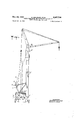
- Fig. 1 is an elevation of a revolving tower crane constructed in accordance with the invention
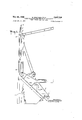
- Fig. 2 is an enlarged fragmentary detail of a portion of the mechanism indicated in Fig. l;
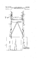
- Fig. 3 is an enlarged fragmentary rear elevation of a portion of the mechanism indicated in Fig. 1.
- the invention comprises the provision, on the upper carriage of the crane, of a counterweight movably journalled about an axis at one side of the perpendicular center of gravity, the counterweight being otherwise securely held by known means.
- the counterweight comprises a hook or eye for establishing connection of the counterweight with the tower support cable through linkage rods.
- numeral 1 designates a counterweight which is swingably journalled about a horizontal axis 2 on the upper carriage 3 of the revolvable tower crane.
- the counterweight 1 is held in balance during assembly of the crane by adjustment of a screw spindle 4, arranged on the upper carriage 3.
- the spindle 4, operative against the lower end of said counterweight is adjusted inwardly to swing and lift said counterweight enough so that the upper end of the interconnected linkage rods 6 i joined at their lower end to an upper eye in the counterweight can be hooked into a central opening in a lever 7 fulcrumed at one end with respect to the upper carriage structure.
- the other end of the lever 7 is bolted to one end of a turnbuckle 8 the other end of which connects with the tower support cable 9.
- the upper end of the tower support cable 9 connects at 10 with the upper end of the tower or mast 5.
- the screw spindle 4 is adjusted so that it is fully withdrawn and removed from abutment with the counterweight 1.
- the counterweight will pull with constant tension upon the lower end of the cable 9 through the link rods 6, the lever 7 and the turnbuckle 8, in the manner of a balance scale.
- the turnbuckle 8 allows additional independent positional adjustment of the counterweight 1.
- Another advantage of the invention is that it eliminates the former extended periods of waiting while turnbuckles were adjusted from time to time to readjust to the desired tension in the support cables.
- the present invention results in over-all improvement in operational security and efliciency.
- a cable tensioning mechanism for revolvable tower cranes and the like, the combination comprising an upper support carriage, an elongated tower supported by said carriage and extending vertically therefrom, a tower support cable secured at one end to an upper portion of said tower and extending downwardly and obliquely therefrom, a counterweight rotatably journalled about a horizontal axis on said carriage, said axis being at one side of the vertical center of gravity line of said counterweight, a lever fulcrumed at one end about a point fixed with respect to said carriage and above said counterweight, first link means interconnecting a central portion in said lever with a portion of said counterweight at the other side of said center of gravity line thereof, and second means linking the other end of said cable with the other end of said lever.
- said first link means comprises a pair of end-to-end articulated rods.
- said second linking means comprises a turnbuckle fixed at one end to the other end of said cable, the other end of said turnbuckle being bolted to said other end of said lever.
- a cable tensioning mechanism for revolvable tower cranes and the like, the combination comprising an upper support carriage, an elongated tower pivotally supported by said carriage for operative movement and extending vertically therefrom, a tower support cable secured at one end to an upper portion of said tower and extending downwardly and obliquely therefrom, a counterweight rotatably journalled about a horizontal axis on said carriage, said axis being at one side of the vertical center of gravity line of said counterweight, and mechanism interconnecting the other end of said cable with said counterweight at the other side of said center of gravity line thereof whereby said counterweight acts as a pendulous balance weight with respect to said cable, to maintain a substantially constant tension on said cable even when said tower is moved and adjustable means for supporting said counterweight from underneath to prevent pendulous rotation about said axis, said counterweight-supporting means comprising a screw spindle supported by said carriage.
Landscapes
- Engineering & Computer Science (AREA)
- Mechanical Engineering (AREA)
- Jib Cranes (AREA)
Description
May 24, 1960 M. WALTHER ETAL CABLE TENSIONING MECHANISM FOR REVOLVABLE TOWER CRANES AND THE LIKE 3 Sheets-Sheet 1 Filed Oct. 3, 1957 INVENTORS 244m 250 Marx/5? May 1960 M. WALTHER ET AL CABLE 2,937,726 TENSIONING MECHANISM FOR REVOLVABLE TOWER CRANES AND THE LIKE Filed. 001;. 3, 1957 3 Sheets-Sheet 2 o 7 "In" o i i v 1 Q 1 Z :7
M/aA rpfs gw fi iw I I GE'fi/IIRD LANG y 1960 M. WALTHER ET AL 2,937,726
CABLE TENSIONING MECHANISM FOR REVOLVABLE TOWER CRANES AND THE LIKE Filed Oct. 3, 1957 3 Sheets-Sheet 3 INVENTORS Mmwzp MLrA/k Gav/MED LI/VG' United States Patent O CABLE TENSIONING MECHANISM FOR REVOLV- ABLE TOWER CRANES AND THE LIKE Manfred Walther and Gerhard Lang, Leipzig, Germany, assignors to Institut fiir Ftirdertechnik des Ministeriums fiir Schwermaschinenbau, Leipzig, Germany Filed Oct. 3, 1957, Ser. No. 687,932
Claims. Cl. 189-11) Our invention relates to revolving tower cranes and is directed particularly to a movably journalled counterweight for producing a constant tension in the main support cable of such cranes.
It is already known to use pre-stressed cables to minimize the oscillations occurring during operation of revolving tower cranes, especially those having high masts. In such cranes turnbuckles are used for adjustably co11- trolling the pre-stressing of the cable. Such arrangements have the disadvantage however that the turnbuckles must often be readjusted since the cables are subject to considerable changes in length due to physical conditions and other influences. Moreover, because of these changes, it is not possible to calculate and apply the proper pre-stress for the supporting cable of a given revolving tower crane.
The foregoing disadvantages result in frequent work stoppage and complicated constructions which obviously are economically unsound.
It is accordingly the principal object of this invention to provide an improved pre-stressing arrangement for revolvable tower crane cables which eliminate the abovedescribed deficiencies.
A more particular object of the invention is to provide in cranes of the character described, a simple and easily operable mechanism in the form of a movably journalled counterweight operative to apply a constant cable pull the amount of which can be precisely calculated in the design and embodied in the construction of the crane.
Other objects, features and advantages of the invention will be apparent from the following description when read with reference to the accompanying drawing illustrating in side elevation a revolvable tower crane embodying, by way of example, one form of cable tensioning device according to the invention.
In the drawings:
Fig. 1 is an elevation of a revolving tower crane constructed in accordance with the invention;
Fig. 2 is an enlarged fragmentary detail of a portion of the mechanism indicated in Fig. l; and
Fig. 3 is an enlarged fragmentary rear elevation of a portion of the mechanism indicated in Fig. 1.
In brief, the invention comprises the provision, on the upper carriage of the crane, of a counterweight movably journalled about an axis at one side of the perpendicular center of gravity, the counterweight being otherwise securely held by known means. The counterweight comprises a hook or eye for establishing connection of the counterweight with the tower support cable through linkage rods. By means of this arrangement, the counterweight applies a constant pulling force to the cable, which is independent of variations in cable length, since the counterweight adjusts itself automatically to such variations. The value of the constant tensional force applied to the cable can, through corresponding positioning of the turning axis of the counterweight on the upper carriage, be adjusted with mathematical precision.
Referring now in detail to the drawing, the reference 2,937,726 Patented May 24, 1960 numeral 1 designates a counterweight which is swingably journalled about a horizontal axis 2 on the upper carriage 3 of the revolvable tower crane. The counterweight 1 is held in balance during assembly of the crane by adjustment of a screw spindle 4, arranged on the upper carriage 3. Subsequent to the assembly of the crane, the spindle 4, operative against the lower end of said counterweight, is adjusted inwardly to swing and lift said counterweight enough so that the upper end of the interconnected linkage rods 6 i joined at their lower end to an upper eye in the counterweight can be hooked into a central opening in a lever 7 fulcrumed at one end with respect to the upper carriage structure. The other end of the lever 7 is bolted to one end of a turnbuckle 8 the other end of which connects with the tower support cable 9. The upper end of the tower support cable 9 connects at 10 with the upper end of the tower or mast 5.
After the linkage rods 6 are hooked in place, the screw spindle 4 is adjusted so that it is fully withdrawn and removed from abutment with the counterweight 1. There after the counterweight will pull with constant tension upon the lower end of the cable 9 through the link rods 6, the lever 7 and the turnbuckle 8, in the manner of a balance scale. The turnbuckle 8 allows additional independent positional adjustment of the counterweight 1. Through use of the lever 7, to which the cable 9 is alfixed by means of the cable bolt 11, the cable can remain in connection with said lever during assembly and use of the crane.
In accordance with the teachings of this invention it is possible to determine the proper tension required in the support cable in accordance with the calculated strength of the tower, whereby a substantial weight reduction can be efiected, at least in the tower construction.
Another advantage of the invention is that it eliminates the former extended periods of waiting while turnbuckles were adjusted from time to time to readjust to the desired tension in the support cables. In addition, the present invention results in over-all improvement in operational security and efliciency.
Though only one form in which the invention may conveniently be embodied in practice is described in this specification, it is to be understood that this form is given by way of illustration only and that the invention is not limited to the particular disclosure, but may be modified and embodied in various other equivalent forms without departing from its spirit. In short, this invention includes all the modifications and embodiments coming within the scope of the following claims.
What is claimed as new and for which it is desired to secure Letters Patent is:
1. In a cable tensioning mechanism for revolvable tower cranes and the like, the combination comprising an upper support carriage, an elongated tower supported by said carriage and extending vertically therefrom, a tower support cable secured at one end to an upper portion of said tower and extending downwardly and obliquely therefrom, a counterweight rotatably journalled about a horizontal axis on said carriage, said axis being at one side of the vertical center of gravity line of said counterweight, a lever fulcrumed at one end about a point fixed with respect to said carriage and above said counterweight, first link means interconnecting a central portion in said lever with a portion of said counterweight at the other side of said center of gravity line thereof, and second means linking the other end of said cable with the other end of said lever.
2. The mechanism as defined in claim 1 wherein said first link means comprises a pair of end-to-end articulated rods.
3. The mechanism as defined in claim 1 wherein said second linking means comprises a turnbuckle fixed at one end to the other end of said cable, the other end of said turnbuckle being bolted to said other end of said lever.
4. The invention as defined in claim 1 including means for adjusting the journalling position of said counterweight with respect to said counterweight for controlling the pendulous weight thereof.
5. In a cable tensioning mechanism for revolvable tower cranes and the like, the combination comprising an upper support carriage, an elongated tower pivotally supported by said carriage for operative movement and extending vertically therefrom, a tower support cable secured at one end to an upper portion of said tower and extending downwardly and obliquely therefrom, a counterweight rotatably journalled about a horizontal axis on said carriage, said axis being at one side of the vertical center of gravity line of said counterweight, and mechanism interconnecting the other end of said cable with said counterweight at the other side of said center of gravity line thereof whereby said counterweight acts as a pendulous balance weight with respect to said cable, to maintain a substantially constant tension on said cable even when said tower is moved and adjustable means for supporting said counterweight from underneath to prevent pendulous rotation about said axis, said counterweight-supporting means comprising a screw spindle supported by said carriage.
References Cited in the file of this patent UNITED STATES PATENTS 2,068,397 Chapman Jan. 19, 1937 2,408,500 West Oct. 1, 1946 FOREIGN PATENTS 505 Great Britain Feb. 11, 1875
Priority Applications (1)
| Application Number | Priority Date | Filing Date | Title |
|---|---|---|---|
| US687932A US2937726A (en) | 1957-10-03 | 1957-10-03 | Cable tensioning mechanism for revolvable tower cranes and the like |
Applications Claiming Priority (1)
| Application Number | Priority Date | Filing Date | Title |
|---|---|---|---|
| US687932A US2937726A (en) | 1957-10-03 | 1957-10-03 | Cable tensioning mechanism for revolvable tower cranes and the like |
Publications (1)
| Publication Number | Publication Date |
|---|---|
| US2937726A true US2937726A (en) | 1960-05-24 |
Family
ID=24762444
Family Applications (1)
| Application Number | Title | Priority Date | Filing Date |
|---|---|---|---|
| US687932A Expired - Lifetime US2937726A (en) | 1957-10-03 | 1957-10-03 | Cable tensioning mechanism for revolvable tower cranes and the like |
Country Status (1)
| Country | Link |
|---|---|
| US (1) | US2937726A (en) |
Cited By (11)
| Publication number | Priority date | Publication date | Assignee | Title |
|---|---|---|---|---|
| US2941172A (en) * | 1957-09-24 | 1960-06-14 | Essex Electronics | Electrical winding construction |
| US3134488A (en) * | 1962-07-20 | 1964-05-26 | Thew Shovel Co | Crane |
| US3202299A (en) * | 1963-07-22 | 1965-08-24 | T S Decuir | Mobile guy derrick and counter balancing crane |
| US20100032213A1 (en) * | 2007-10-24 | 2010-02-11 | T&T Engineering Services | Apparatus and method for pre-loading of a main rotating structural member |
| US20100230166A1 (en) * | 2009-03-12 | 2010-09-16 | T&T Engineering Services | Derrickless tubular servicing system and method |
| US20100296899A1 (en) * | 2009-05-20 | 2010-11-25 | T&T Engineering Services | Alignment apparatus and method for a boom of a pipe handling system |
| US8192129B1 (en) | 2007-10-24 | 2012-06-05 | T&T Engineering Services, Inc. | Pipe handling boom pretensioning apparatus |
| US8419335B1 (en) | 2007-10-24 | 2013-04-16 | T&T Engineering Services, Inc. | Pipe handling apparatus with stab frame stiffening |
| US20150167408A1 (en) * | 2009-05-20 | 2015-06-18 | T&T Engineering Services, Inc. | Alignment Apparatus and Method for a Boom of a Pipe Handling System |
| US9091128B1 (en) | 2011-11-18 | 2015-07-28 | T&T Engineering Services, Inc. | Drill floor mountable automated pipe racking system |
| US9476267B2 (en) | 2013-03-15 | 2016-10-25 | T&T Engineering Services, Inc. | System and method for raising and lowering a drill floor mountable automated pipe racking system |
Citations (2)
| Publication number | Priority date | Publication date | Assignee | Title |
|---|---|---|---|---|
| US2068397A (en) * | 1935-06-01 | 1937-01-19 | Chapman Paul | Crane construction |
| US2408500A (en) * | 1944-09-13 | 1946-10-01 | Maxwell A West | Automatic counterbalance for boom derricks |
-
1957
- 1957-10-03 US US687932A patent/US2937726A/en not_active Expired - Lifetime
Patent Citations (2)
| Publication number | Priority date | Publication date | Assignee | Title |
|---|---|---|---|---|
| US2068397A (en) * | 1935-06-01 | 1937-01-19 | Chapman Paul | Crane construction |
| US2408500A (en) * | 1944-09-13 | 1946-10-01 | Maxwell A West | Automatic counterbalance for boom derricks |
Cited By (18)
| Publication number | Priority date | Publication date | Assignee | Title |
|---|---|---|---|---|
| US2941172A (en) * | 1957-09-24 | 1960-06-14 | Essex Electronics | Electrical winding construction |
| US3134488A (en) * | 1962-07-20 | 1964-05-26 | Thew Shovel Co | Crane |
| US3202299A (en) * | 1963-07-22 | 1965-08-24 | T S Decuir | Mobile guy derrick and counter balancing crane |
| US20100032213A1 (en) * | 2007-10-24 | 2010-02-11 | T&T Engineering Services | Apparatus and method for pre-loading of a main rotating structural member |
| US8696288B2 (en) | 2007-10-24 | 2014-04-15 | T&T Engineering Services, Inc. | Pipe handling boom pretensioning apparatus |
| US8469648B2 (en) * | 2007-10-24 | 2013-06-25 | T&T Engineering Services | Apparatus and method for pre-loading of a main rotating structural member |
| US8419335B1 (en) | 2007-10-24 | 2013-04-16 | T&T Engineering Services, Inc. | Pipe handling apparatus with stab frame stiffening |
| US8192129B1 (en) | 2007-10-24 | 2012-06-05 | T&T Engineering Services, Inc. | Pipe handling boom pretensioning apparatus |
| US8371790B2 (en) | 2009-03-12 | 2013-02-12 | T&T Engineering Services, Inc. | Derrickless tubular servicing system and method |
| US20100230166A1 (en) * | 2009-03-12 | 2010-09-16 | T&T Engineering Services | Derrickless tubular servicing system and method |
| US8192128B2 (en) * | 2009-05-20 | 2012-06-05 | T&T Engineering Services, Inc. | Alignment apparatus and method for a boom of a pipe handling system |
| US20100296899A1 (en) * | 2009-05-20 | 2010-11-25 | T&T Engineering Services | Alignment apparatus and method for a boom of a pipe handling system |
| US8905699B2 (en) | 2009-05-20 | 2014-12-09 | T&T Engineering Services, Inc. | Alignment apparatus and method for a boom of a pipe handling system |
| US20150167408A1 (en) * | 2009-05-20 | 2015-06-18 | T&T Engineering Services, Inc. | Alignment Apparatus and Method for a Boom of a Pipe Handling System |
| US9556689B2 (en) * | 2009-05-20 | 2017-01-31 | Schlumberger Technology Corporation | Alignment apparatus and method for a boom of a pipe handling system |
| US9091128B1 (en) | 2011-11-18 | 2015-07-28 | T&T Engineering Services, Inc. | Drill floor mountable automated pipe racking system |
| US9945193B1 (en) | 2011-11-18 | 2018-04-17 | Schlumberger Technology Corporation | Drill floor mountable automated pipe racking system |
| US9476267B2 (en) | 2013-03-15 | 2016-10-25 | T&T Engineering Services, Inc. | System and method for raising and lowering a drill floor mountable automated pipe racking system |
Similar Documents
| Publication | Publication Date | Title |
|---|---|---|
| US2937726A (en) | Cable tensioning mechanism for revolvable tower cranes and the like | |
| US4579504A (en) | Crane for lifting device such as fork lift | |
| US3202299A (en) | Mobile guy derrick and counter balancing crane | |
| US3072265A (en) | Boom rigging | |
| US3065861A (en) | Rope crane | |
| US1871603A (en) | Automatic hoist boom | |
| US2378915A (en) | Suspension for crane booms | |
| US2924341A (en) | Pulley assembly for cranes | |
| US3339652A (en) | Load weight indicator installation for cranes, derricks and the like | |
| JPH0694348B2 (en) | Lattice mast type crane | |
| GB702896A (en) | An improved self-supporting adjustable and movable screen for protection against sunor wind | |
| US2338317A (en) | Portable derrick | |
| US3933250A (en) | Guy crane jib tip prop | |
| CN116081454A (en) | Clamping mechanism for hanging steel beam | |
| US3028697A (en) | Loading boom | |
| US3062384A (en) | Boom and jib assembly | |
| US2356255A (en) | Clamshell bucket | |
| US2858945A (en) | Pivoting and hoisting arrangement for the distributing assembly of a tower crane | |
| US2570417A (en) | Hoisting apparatus | |
| SU471285A1 (en) | Crane for lifting building materials through the window opening of the building | |
| US2787344A (en) | Portable oil well mast with folding gin pole | |
| US3368695A (en) | Device for hoisting loads, for example antennae on towers or masts | |
| GB1017761A (en) | Apparatus for measuring the angular displacement of a vessel from a desired location | |
| US1653834A (en) | Crane | |
| US3892316A (en) | Crane with folding mast and jib |