US2932220A - Three speed combination transmission and axle - Google Patents
Three speed combination transmission and axle Download PDFInfo
- Publication number
- US2932220A US2932220A US569360A US56936056A US2932220A US 2932220 A US2932220 A US 2932220A US 569360 A US569360 A US 569360A US 56936056 A US56936056 A US 56936056A US 2932220 A US2932220 A US 2932220A
- Authority
- US
- United States
- Prior art keywords
- transmission
- housing
- gear
- ring gear
- speed
- Prior art date
- Legal status (The legal status is an assumption and is not a legal conclusion. Google has not performed a legal analysis and makes no representation as to the accuracy of the status listed.)
- Expired - Lifetime
Links
- 230000005540 biological transmission Effects 0.000 title description 32
- 150000001875 compounds Chemical class 0.000 description 3
- 230000008878 coupling Effects 0.000 description 3
- 238000010168 coupling process Methods 0.000 description 3
- 238000005859 coupling reaction Methods 0.000 description 3
- 230000000694 effects Effects 0.000 description 2
- 241000282441 Helarctos malayanus Species 0.000 description 1
- 241000269319 Squalius cephalus Species 0.000 description 1
- 238000006243 chemical reaction Methods 0.000 description 1
- 239000007787 solid Substances 0.000 description 1
- 239000000725 suspension Substances 0.000 description 1
Images
Classifications
-
- F—MECHANICAL ENGINEERING; LIGHTING; HEATING; WEAPONS; BLASTING
- F16—ENGINEERING ELEMENTS AND UNITS; GENERAL MEASURES FOR PRODUCING AND MAINTAINING EFFECTIVE FUNCTIONING OF MACHINES OR INSTALLATIONS; THERMAL INSULATION IN GENERAL
- F16H—GEARING
- F16H47/00—Combinations of mechanical gearing with fluid clutches or fluid gearing
- F16H47/06—Combinations of mechanical gearing with fluid clutches or fluid gearing the fluid gearing being of the hydrokinetic type
- F16H47/08—Combinations of mechanical gearing with fluid clutches or fluid gearing the fluid gearing being of the hydrokinetic type the mechanical gearing being of the type with members having orbital motion
Definitions
- the invention relates particularly to an automatic transmission having a housing which is adapted to be positioned immediately adjacent the differential housing of a vehicle and fixedly attached thereto. If the transmission of an automotive vehicle can be positioned near the dilferential housing of the vehicle, the tunnel or hump in the frame and floor of the vehicle, which is normally provided just behind the engine to accommodate the transmission, can be eliminated.
- Another object of the invention is to provide a new.
- main housing 10 In the illustrated embodiment of the invention main housing 10 is shown as being positioned immediately adjacent and rigidly attached to a differential housing 11. It will be understood, however, that the new and improved transmission of the present invention also has general utility and need not necessarily be used in combination with a differential housing in the manner illustrated.
- the left side of the transmission is referred to as the input end and the right side of the transmission is referred to as the output end.
- the transmission housing 10 and the differential housing 11 form a rigid unit which may represent a sprung or unsprung mass depending upon the design of the suspension system of the vehicle in which the transmission of the present invention is incorporated.
- Transmission housing 10 is generally cylindrical in shape and is somewhat larger at the output end thereof than at the input end. Transmission housing 10 and the components therein are designed so that the outer diameter of housing 10 is as small as practicable so that as much road clearance as possible is obtained.
- a transmission drive shaft 12 is provided for receiving torque transmitted from the engine of the vehicle to the transmission.
- Drive shaft 12 extends from the input end of the transmission to a point just short of the output end of the transmission.
- a driven shaft 13 is provided at the output end of the transmission which is colinear with drive shaft 12 and is provided with a pinion 14 which engages a differential ring gear 15 in power transmitting relation. 7
- Speed-upgear. set 24 comprises a sun gear 25 fixedly attached to an annularsleeve 26, a ring gear 27 fixedly connected' to impeller 21, planet gears 28 disposed between sun overrunning clutch 30 becomes operative to drive ring gear 27 at the same speed as the cage or planet gear carrier 29 to produce a one to one speed ratio between drive shaft 12 and impeller 21.
- Reaction member23 is operably connected to the case it or housing 10 through an overrunning clutch 4t and a stationary annular sleeve member 41 in a conventional manner.
- the main gear set 46 includes a rear sun gear 47, a front sun gear 48, a ring gear 49, planets 50 disposed between rear sun gear 46 and ring gear 49 and in meshing engagement therewith, planets 51 disposed between front sun gear 48 and planets 50 and in meshing engagement therewith, and a compound cage or planet gear carrier 52 upon which planets 50 and 51 are rotatably disposed and carried.
- the rear sun gear 47 is fixedly connected to turbine 22 through an annular sleeve 55.
- the front sun gear .48 may be selectively locked to the case or housing 10 through a rotatable annular sleeve 56, a drum 57, and a friction brake 58 which is engageable with drum 57.
- Ring gear 49 has associated therewith a drum 60, connectable thereto by a rotatable annular sleeve 61, and a friction brake 62 which is engageable with drum 60 for selectively locking ring gear 49 to the case or housing 10.
- a friction clutch 63 Operably disposed between ring gear 49 and one end of planet gear carrier 52 is a friction clutch 63 for selectively locking these members together.
- output member 68 which extends around the outside of converter 20 and is Operably connected to driven shaft 13.
- output member '68 includes, by way of example, an axially extending portion 69 and radially extending portions 70 and 71 which connect output member 68 to cage 52 and the driven shaft 13. It is the output member 68 which transmits power from the main planetary gear set 46 to pinion 14 which drives differential ring gear 15.
- the output member 68 by reason of its extending around converter 20 may be utilized as a housing for converter 20 and this is a primary feature of the invention.
- the speed-up gear set 24 may be operated selectively to provide two speed ratios at that stage by operating the friction coupling 35 so that imgear 25 and ring gear 27 in meshing engagement therewith, and a planet gear carrier 29 hav- 1 ing one end thereof fixedly connected to drive shaft-12,
- a friction 3 peller 21 is either overdriven by drive shaft 12 or driven at the same speed as drive shaft 12 through overrunniug clutch '30.
- low speed, high torque operation is obtained by applying brake 58 to drum 57' to lock the front sun gear 48 to the case.
- Brake 62 and clutch 63 are disengaged and there is a speed reduction through the planetary gearing 46 as rotary motion is transmitted from impeller 22 through rear sungear 47 to the cage or planet gear carrier 52.
- the rotary motion of cage 52 which may represent a reduction on the order of about 1.8 for example, is transmitted around converter 20 through the axially extended portion 68 of cage 52 to driven shaft 13.
- High speed operation is obtained byreleasing hrake S8 to permit rotation of front sun gear 48, applying clutch 63 so that cage 52 and ring gear 49 are locked together, and. maintaining brake 62 in its released position. This has the effect of causing cage 52 and ring gear $9 to rotate together and produces a higher speed ratio
- the gearing may be designed to produce a one to one ratio between rear sun gear 47 and cage 52, for example.
- Reverse operation is obtained by releasing brake '58 to permit rotation of front sun gear 48, releasing clutch 63 between ring gear 49 and cage 52, and applying'brake 62 to lock ring gear 49 to the case.
- the compound or double planetary pinions G and 51 produces reversed rotation of the cage 52 relative to the rotation of rear sun bear 47.- As mentioned above, pinions 50 are in mesh with pinions 51. 7
- Converter 20 is arranged so that impeller 21 faces the input or left end of the transmission and turbine 22 faces the output or right end of-the transmission.
- Speed-up gear set 24 is positioned between the converter 20 and the output end of the transmission.
- the main gear set 46 is positioned between the converter 21) andthe input end of-the transmission.
- the drive from turbine 21 is transmitted to the gear set 46 and from cage 52 of gear set 46 through output member 68 around the converter 20 and speed-up gear set 24 to the driven shaft 13.
- Output member 68 The invention may be embodied in other specific forms without departing from the spirit or essential character istics thereof.
- a main housing In a transmission, a main housing; a drive shaft; a driven shaft; a hydraulic torque converter operably disposed between said drive shaft and said driven shaft comprising an impeller, a turbine and a reactor, said reactor being operably connected to said housing through a one-way brake; a speed-up planetary gear set operably disposed between said drive shaft and said converter comprising a sun gear rotatably mounted relative to said main housing, a ring gear fixedlyconnected to said impeller, a planet gear disposed between and in mesh with said ring gear and said sun gear, a planet carrier fixedly connected to said drive shaft and operably connected to said ring gear through a one-way clutch; a friction brake disposed between said sun gear and said housing; a main planetary gear set operably disposed between said turbine and said driven shaft comprising a first sun rotatably mounted relative to said housing, a second sun operably connectedv to an driven by said turbine, a main ring gear, a compound planet gear having one set of planets in mesh with
- the feature of driving into converter 20 from the speed-up gear set 24 and directing the output from the main gear set 46 around the outside of converted 28 has the effect of turning the transmission around backwards for space utilization without reversing the components of the transmission or necessitating the providing of a lefthanded converter.
- said one set of planets, and a planet carrier having a portion thereof extending around the'outside of said converter and being operably connected to said driven shaft in driving-relation; a brake drum and friction brake set operably disposed between said first sun gear and said housing; a brake drum and a friction brake set operably disposed between said main ring gear and saidhousing; and azfriction coupling disposed between said main ringigear and said carrier arm.
Landscapes
- Engineering & Computer Science (AREA)
- General Engineering & Computer Science (AREA)
- Mechanical Engineering (AREA)
- Structure Of Transmissions (AREA)
Description
E. L. NASH April 12, 1960 THREE SPEED COMBINATION TRANSMISSION AND AXLE Filed March 5, 1956 INVENTOR.
dwa/cd www w v M M nm Mun .0 e H 1 7/ a m m bu on on 0N I V 0 0 b III. R. 5 m0 8 THREE SPEED COMBINATION TRANSMISSION AND AXLE This invention relates to automatic transmissions for automotive vehicles and other vehicles.
The invention relates particularly to an automatic transmission having a housing which is adapted to be positioned immediately adjacent the differential housing of a vehicle and fixedly attached thereto. If the transmission of an automotive vehicle can be positioned near the dilferential housing of the vehicle, the tunnel or hump in the frame and floor of the vehicle, which is normally provided just behind the engine to accommodate the transmission, can be eliminated.
It is a main object of the invention to provide a new and improved automatic transmission for automotive vehicles and other vehicles.
Another object of the invention is to provide a new.
and improved automatic transmission having a housing which is adapted to be positioned immediately adjacent and fixedly attached to the differential housing of a vehicle.
Other objects of the invention will become apparent from the following specification, the drawing relating thereto, and the appended claim. i
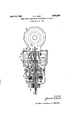
In the drawing there is shown in side elevation a schematic view of a new and improved automatic transmission embodying the present invention.
In the drawing the transmission is shown as having a. main housing 10. In the illustrated embodiment of the invention main housing 10 is shown as being positioned immediately adjacent and rigidly attached to a differential housing 11. It will be understood, however, that the new and improved transmission of the present invention also has general utility and need not necessarily be used in combination with a differential housing in the manner illustrated.
In general, and for convenience in describing the illustrated embodiment of the invention, the left side of the transmission is referred to as the input end and the right side of the transmission is referred to as the output end.
The transmission housing 10 and the differential housing 11 form a rigid unit which may represent a sprung or unsprung mass depending upon the design of the suspension system of the vehicle in which the transmission of the present invention is incorporated. Transmission housing 10 is generally cylindrical in shape and is somewhat larger at the output end thereof than at the input end. Transmission housing 10 and the components therein are designed so that the outer diameter of housing 10 is as small as practicable so that as much road clearance as possible is obtained.
A transmission drive shaft 12 is provided for receiving torque transmitted from the engine of the vehicle to the transmission. Drive shaft 12 extends from the input end of the transmission to a point just short of the output end of the transmission. A driven shaft 13 is provided at the output end of the transmission which is colinear with drive shaft 12 and is provided with a pinion 14 which engages a differential ring gear 15 in power transmitting relation. 7
United States v Patent 2,932,220 Patented Apr. 12, 1960 "ice ' tion. Speed-upgear. set 24 comprises a sun gear 25 fixedly attached to an annularsleeve 26, a ring gear 27 fixedly connected' to impeller 21, planet gears 28 disposed between sun overrunning clutch 30 becomes operative to drive ring gear 27 at the same speed as the cage or planet gear carrier 29 to produce a one to one speed ratio between drive shaft 12 and impeller 21.
Reaction member23 is operably connected to the case it or housing 10 through an overrunning clutch 4t and a stationary annular sleeve member 41 in a conventional manner.
Operably disposed between converter turbine 22 and driving shaft 13 is a main planetary gear set 46. The main gear set 46 includes a rear sun gear 47, a front sun gear 48, a ring gear 49, planets 50 disposed between rear sun gear 46 and ring gear 49 and in meshing engagement therewith, planets 51 disposed between front sun gear 48 and planets 50 and in meshing engagement therewith, and a compound cage or planet gear carrier 52 upon which planets 50 and 51 are rotatably disposed and carried.
The rear sun gear 47 is fixedly connected to turbine 22 through an annular sleeve 55. The front sun gear .48 may be selectively locked to the case or housing 10 through a rotatable annular sleeve 56, a drum 57, and a friction brake 58 which is engageable with drum 57.
Ring gear 49 has associated therewith a drum 60, connectable thereto by a rotatable annular sleeve 61, and a friction brake 62 which is engageable with drum 60 for selectively locking ring gear 49 to the case or housing 10. Operably disposed between ring gear 49 and one end of planet gear carrier 52 is a friction clutch 63 for selectively locking these members together.
Cage or planet gear carrier 52 has attached thereto an output member 68 which extends around the outside of converter 20 and is Operably connected to driven shaft 13. As illustrated herein output member '68 includes, by way of example, an axially extending portion 69 and radially extending portions 70 and 71 which connect output member 68 to cage 52 and the driven shaft 13. It is the output member 68 which transmits power from the main planetary gear set 46 to pinion 14 which drives differential ring gear 15. The output member 68, by reason of its extending around converter 20 may be utilized as a housing for converter 20 and this is a primary feature of the invention.
In the operation of the transmission the speed-up gear set 24, if it is used instead of a solid coupling, may be operated selectively to provide two speed ratios at that stage by operating the friction coupling 35 so that imgear 25 and ring gear 27 in meshing engagement therewith, and a planet gear carrier 29 hav- 1 ing one end thereof fixedly connected to drive shaft-12,
A friction 3 peller 21 is either overdriven by drive shaft 12 or driven at the same speed as drive shaft 12 through overrunniug clutch '30.
Referring to the main planetary gear set 46, low speed, high torque operation is obtained by applying brake 58 to drum 57' to lock the front sun gear 48 to the case. Brake 62 and clutch 63 are disengaged and there is a speed reduction through the planetary gearing 46 as rotary motion is transmitted from impeller 22 through rear sungear 47 to the cage or planet gear carrier 52. The rotary motion of cage 52,which may represent a reduction on the order of about 1.8 for example, is transmitted around converter 20 through the axially extended portion 68 of cage 52 to driven shaft 13.
High speed operation is obtained byreleasing hrake S8 to permit rotation of front sun gear 48, applying clutch 63 so that cage 52 and ring gear 49 are locked together, and. maintaining brake 62 in its released position. This has the effect of causing cage 52 and ring gear $9 to rotate together and produces a higher speed ratio The gearing may be designed to produce a one to one ratio between rear sun gear 47 and cage 52, for example.
Reverse operation is obtained by releasing brake '58 to permit rotation of front sun gear 48, releasing clutch 63 between ring gear 49 and cage 52, and applying'brake 62 to lock ring gear 49 to the case. The compound or double planetary pinions G and 51 produces reversed rotation of the cage 52 relative to the rotation of rear sun bear 47.- As mentioned above, pinions 50 are in mesh with pinions 51. 7
Reference is now made to the general positioning of the components of the transmission. Converter 20 is arranged so that impeller 21 faces the input or left end of the transmission and turbine 22 faces the output or right end of-the transmission. Speed-up gear set 24 is positioned between the converter 20 and the output end of the transmission. The main gear set 46 is positioned between the converter 21) andthe input end of-the transmission. The drive from turbine 21 is transmitted to the gear set 46 and from cage 52 of gear set 46 through output member 68 around the converter 20 and speed-up gear set 24 to the driven shaft 13. Output member 68 The invention may be embodied in other specific forms without departing from the spirit or essential character istics thereof. The present embodiment of the invention is therefore to be considered-in all respects as illustrative and not restrictive, the scope of the invention being indicated by the appended claim rather than by the foregoing description, and all changes which come within the meaning and range of equivalency of the claim are therefore intended to be embraced therein.
It is claimed and desired to secure by Letters Patent:
In a transmission, a main housing; a drive shaft; a driven shaft; a hydraulic torque converter operably disposed between said drive shaft and said driven shaft comprising an impeller, a turbine and a reactor, said reactor being operably connected to said housing through a one-way brake; a speed-up planetary gear set operably disposed between said drive shaft and said converter comprising a sun gear rotatably mounted relative to said main housing, a ring gear fixedlyconnected to said impeller, a planet gear disposed between and in mesh with said ring gear and said sun gear, a planet carrier fixedly connected to said drive shaft and operably connected to said ring gear through a one-way clutch; a friction brake disposed between said sun gear and said housing; a main planetary gear set operably disposed between said turbine and said driven shaft comprising a first sun rotatably mounted relative to said housing, a second sun operably connectedv to an driven by said turbine, a main ring gear, a compound planet gear having one set of planets in mesh with said second sun and said main ring gear and another set of planets in mesh with saidfirst sun gearrand is preferably in the form of a housing which functions as'a housing for converter 20.
The feature of driving into converter 20 from the speed-up gear set 24 and directing the output from the main gear set 46 around the outside of converted 28 has the effect of turning the transmission around backwards for space utilization without reversing the components of the transmission or necessitating the providing of a lefthanded converter.
said one set of planets, and a planet carrier having a portion thereof extending around the'outside of said converter and being operably connected to said driven shaft in driving-relation; a brake drum and friction brake set operably disposed between said first sun gear and said housing; a brake drum and a friction brake set operably disposed between said main ring gear and saidhousing; and azfriction coupling disposed between said main ringigear and said carrier arm.
References Cited in the file of this patent UNITED STATES PATENTS 1,242,974 Pinckney Oct. 16, 1917 2,281,077 Pollard Apr. 28, 1942 2,351,213 James "June 13, 1944 2,598,876 Ash June 3, 1952 2;687,657 Kugel et a1. Aug. 31, 1954 2,693,260 Lucia Nov. 2, 1954
Priority Applications (1)
| Application Number | Priority Date | Filing Date | Title |
|---|---|---|---|
| US569360A US2932220A (en) | 1956-03-05 | 1956-03-05 | Three speed combination transmission and axle |
Applications Claiming Priority (1)
| Application Number | Priority Date | Filing Date | Title |
|---|---|---|---|
| US569360A US2932220A (en) | 1956-03-05 | 1956-03-05 | Three speed combination transmission and axle |
Publications (1)
| Publication Number | Publication Date |
|---|---|
| US2932220A true US2932220A (en) | 1960-04-12 |
Family
ID=24275122
Family Applications (1)
| Application Number | Title | Priority Date | Filing Date |
|---|---|---|---|
| US569360A Expired - Lifetime US2932220A (en) | 1956-03-05 | 1956-03-05 | Three speed combination transmission and axle |
Country Status (1)
| Country | Link |
|---|---|
| US (1) | US2932220A (en) |
Cited By (9)
| Publication number | Priority date | Publication date | Assignee | Title |
|---|---|---|---|---|
| US3021726A (en) * | 1957-04-24 | 1962-02-20 | Gen Motors Corp | Transmission |
| US3062074A (en) * | 1958-02-19 | 1962-11-06 | Gen Motors Corp | Multi-phase transmission |
| US3107555A (en) * | 1956-10-13 | 1963-10-22 | Daimler Benz Ag | Change speed transmission |
| US3132536A (en) * | 1956-10-12 | 1964-05-12 | Sampietro Achilte Carlo | Transmission system including fluid torque converter and epicyclic change speed gearing |
| US3256751A (en) * | 1962-10-22 | 1966-06-21 | Gen Motors Corp | Transmission |
| US3355966A (en) * | 1964-08-10 | 1967-12-05 | Gen Motors Corp | Power transmission |
| US4452099A (en) * | 1981-08-17 | 1984-06-05 | Ford Motor Company | Three speed overdrive transaxle assembly |
| WO1985001785A1 (en) * | 1983-10-11 | 1985-04-25 | Ford Motor Company | Hydromechanical transmission with split torque and regenerative torque flow paths |
| US4756210A (en) * | 1984-07-30 | 1988-07-12 | Ford Motor Company | Torque converter bypass for an automatic transmission mechanism |
Citations (6)
| Publication number | Priority date | Publication date | Assignee | Title |
|---|---|---|---|---|
| US1242974A (en) * | 1914-02-06 | 1917-10-16 | Thomas D W Pinckney | Power-transmission mechanism. |
| US2281077A (en) * | 1939-09-20 | 1942-04-28 | Willard L Pollard | Variable speed transmission |
| US2351213A (en) * | 1941-08-21 | 1944-06-13 | Studebaker Corp | Transmission |
| US2598876A (en) * | 1947-07-01 | 1952-06-03 | Charles S Ash | Driven wheel assembly, including hydraulic transmission means |
| US2687657A (en) * | 1950-02-27 | 1954-08-31 | Voith Maschf J M | Fluid drive |
| US2693260A (en) * | 1950-03-07 | 1954-11-02 | Packard Motor Car Co | Clutch and brake for transmissions |
-
1956
- 1956-03-05 US US569360A patent/US2932220A/en not_active Expired - Lifetime
Patent Citations (6)
| Publication number | Priority date | Publication date | Assignee | Title |
|---|---|---|---|---|
| US1242974A (en) * | 1914-02-06 | 1917-10-16 | Thomas D W Pinckney | Power-transmission mechanism. |
| US2281077A (en) * | 1939-09-20 | 1942-04-28 | Willard L Pollard | Variable speed transmission |
| US2351213A (en) * | 1941-08-21 | 1944-06-13 | Studebaker Corp | Transmission |
| US2598876A (en) * | 1947-07-01 | 1952-06-03 | Charles S Ash | Driven wheel assembly, including hydraulic transmission means |
| US2687657A (en) * | 1950-02-27 | 1954-08-31 | Voith Maschf J M | Fluid drive |
| US2693260A (en) * | 1950-03-07 | 1954-11-02 | Packard Motor Car Co | Clutch and brake for transmissions |
Cited By (10)
| Publication number | Priority date | Publication date | Assignee | Title |
|---|---|---|---|---|
| US3132536A (en) * | 1956-10-12 | 1964-05-12 | Sampietro Achilte Carlo | Transmission system including fluid torque converter and epicyclic change speed gearing |
| US3107555A (en) * | 1956-10-13 | 1963-10-22 | Daimler Benz Ag | Change speed transmission |
| US3021726A (en) * | 1957-04-24 | 1962-02-20 | Gen Motors Corp | Transmission |
| US3062074A (en) * | 1958-02-19 | 1962-11-06 | Gen Motors Corp | Multi-phase transmission |
| US3256751A (en) * | 1962-10-22 | 1966-06-21 | Gen Motors Corp | Transmission |
| US3355966A (en) * | 1964-08-10 | 1967-12-05 | Gen Motors Corp | Power transmission |
| US4452099A (en) * | 1981-08-17 | 1984-06-05 | Ford Motor Company | Three speed overdrive transaxle assembly |
| WO1985001785A1 (en) * | 1983-10-11 | 1985-04-25 | Ford Motor Company | Hydromechanical transmission with split torque and regenerative torque flow paths |
| US4592250A (en) * | 1983-10-11 | 1986-06-03 | Ford Motor Company | Hydromechanical transmission with split torque and regenerative torque flow paths |
| US4756210A (en) * | 1984-07-30 | 1988-07-12 | Ford Motor Company | Torque converter bypass for an automatic transmission mechanism |
Similar Documents
| Publication | Publication Date | Title |
|---|---|---|
| US4417484A (en) | Planetary change-speed transmission for automotive vehicles | |
| US3029662A (en) | Power transmission system | |
| US3602055A (en) | Transmission | |
| US3270585A (en) | Transmission | |
| US4003273A (en) | Multi-ratio transmission systems | |
| US2932220A (en) | Three speed combination transmission and axle | |
| US2042189A (en) | Hydrodynamic gear | |
| US2749773A (en) | Hydrodynamically driven planetary transmission | |
| US3020781A (en) | Transmission mechanism | |
| US3584520A (en) | Transmission | |
| US3025721A (en) | Transmission | |
| US3217563A (en) | Duplex gear transmission and hydrodynamic drive combination | |
| US3355966A (en) | Power transmission | |
| US2919604A (en) | Transmission | |
| US3446095A (en) | Transverse automotive vehicle driveline with a four-speed ratio automatic transmission and simulated overdrive | |
| US3491617A (en) | Hydrokinetic torque converter transmission mechanism with an overdrive gear ratio | |
| US2291120A (en) | Power transmission | |
| US2996932A (en) | Vehicle drive | |
| US2910893A (en) | Reversing device for vehicles with torque converter-transmission | |
| GB916639A (en) | Variable speed transmissions for automotive vehicles | |
| US3859872A (en) | Automotive transmission | |
| US2609708A (en) | Transmission | |
| US4545264A (en) | Automatic differential transmission gear | |
| US2939341A (en) | Transmission | |
| US3009369A (en) | Transmission |