US293133A - William ii - Google Patents
William ii Download PDFInfo
- Publication number
- US293133A US293133A US293133DA US293133A US 293133 A US293133 A US 293133A US 293133D A US293133D A US 293133DA US 293133 A US293133 A US 293133A
- Authority
- US
- United States
- Prior art keywords
- grain
- passages
- pipes
- sides
- drier
- Prior art date
- Legal status (The legal status is an assumption and is not a legal conclusion. Google has not performed a legal analysis and makes no representation as to the accuracy of the status listed.)
- Expired - Lifetime
Links
Images

Classifications
-
- F—MECHANICAL ENGINEERING; LIGHTING; HEATING; WEAPONS; BLASTING
- F26—DRYING
- F26B—DRYING SOLID MATERIALS OR OBJECTS BY REMOVING LIQUID THEREFROM
- F26B17/00—Machines or apparatus for drying materials in loose, plastic, or fluidised form, e.g. granules, staple fibres, with progressive movement
- F26B17/12—Machines or apparatus for drying materials in loose, plastic, or fluidised form, e.g. granules, staple fibres, with progressive movement with movement performed solely by gravity, i.e. the material moving through a substantially vertical drying enclosure, e.g. shaft
- F26B17/16—Machines or apparatus for drying materials in loose, plastic, or fluidised form, e.g. granules, staple fibres, with progressive movement with movement performed solely by gravity, i.e. the material moving through a substantially vertical drying enclosure, e.g. shaft the materials passing down a heated surface, e.g. fluid-heated closed ducts or other heating elements in contact with the moving stack of material
Definitions
- WVILLL-LM HEX-RY APPLEG-ATE OF ATLANTIC, IO ⁇ VA.
- the object of my invention is to provide a graindrying apparatus of simple construcapparatus, provision being also made for the escape of the moisture from the grain, and for the passage of air to be heated from below,
- Fig. 2 is a longitudinal sectional elevation on linear m, Fig. 1.
- Fig. 3 is a bottomview; and
- Fig. 4 is a sectional elevation, in part, of the heating apparatus on lines 2, Fig. 1.
- the grain-passages I which Ifix at-their tops preferably to the lower end of the feed-hopper a, by their end bars, I), the hopper-botton1 being fittedwith wood or metal plates or strips 7 c, inclining downwardto the open months or tops of passages b, as in Fig. 2, the bottoms of the passages I) being stayed in position by the casings of the graindischarge, valves, to be hereinafter described, and so that the pas,- sages I) will be held firmly and parallel with each other.
- I make the passages b with sides (I, of wire, of suitable mesh to retain the grain, the sides being spaced about an inch.
- I For effective readily-controllable valves, through which to discharge the driedgraiu frompassages b, I provide slide-valves f,which work .in slots cut or cast alongthe innerlower sides of the valve-casing g, which I make, preferably, in two partsywith a central joint, 71, along the bottom, so that the two side parts of the casin g can readily be slipped over the lower ends of the passages 12, and bolted or otherwise firmly secured thereto; and I flare the sides of casings g outward toward the bottom to admit of using wide valves f, having large apertures t, which may be brought to coincide with the apertures j of the bottoms of the casings-g, for discharge of the grain quickly when required, and by making the valve-casings g in two parts divided at h along the center of apertures j, I provide for casting the casings without cores,and cheaply,and so as to require little or no finish prior to adjustment on the passages b.
- valvecasings 9 may be secured to the casing to at the back end, and should be otherwise supported between the discharge-apertures j at the bottom by suitable cross-bars fixed to or built in the casing a, for sustaining the loaded grain-passages Z, and relieving them of unnecessary strain.
- valves f To work the valves f, I connect them by rods Zwith straps of eccentrics m, fitted opposite the ends of the valves on a shaft, 11, to be turned by any suitable wheel or crank, 0, either slower or fast-er, to discharge the grain faster or slower, according to the time required in drying it; and the eccentrics m will preferably be set to work all the valves f of a drier simultaneously.
- My improved heater for drying the grain in the passages Z1 consists of a series of verticallyranging hollow bars or pipes, p, connected by suitable nipples, q, with a lower transverse steam or other heatconveying pipe, 4', which is supported suitably in the side walls of case a, and has the heat-supply and exhaust pipes r a at opposite ends, the heads of pipes 99 being connected by the transverse support and stay p, about parallel with pipe 1'', which stay p may either be solid or have interior passages connecting pipes p with each other, said pipes 19 being located in front of and in line with the center of the spaces between the grain-passages I), so that the U-pipes s, ranging horizontally through the drier, will be held by their con necting-nipples t, along the sides (Z of grainpassages Z), said pipes .sbeing supported at their backs or bends s in any suitable sockets, 8 sustaining them vertically and against lat eral movement, so that the entire system
- the heater I cut an opening for a door, a, for access to the heater-pipes, which opening may be fitted with a sheet-metal plate, V, to form dead-air spaces for better confining the heat to the interior of the casing, which latter, if built of wood, may also be lined on its inner faces with sheet metal or any suilable non-conducter of heat, for safety against fire, and for economy of fuel.
- the head a of the casing a, or the casing itself, at or near the top, is fitted with apertures or pipes 10, for discharge of the steam andmoisture driven from the grain in drying, and said pipes 10 may be controlled by any suit able dampers, if desired.
- the grain is fed to passages b from the hopper c as fast as it is discharged by the valves f below, which valves are worked by eccentrics m, to deliver the dried grain into a suitable hopper or pit, to be conveyed or elevated therefrom by any approved apparatus for transportation or storage.
- I may connect one or more suitable valve-controlled pipes to discharge steam into the drier in emergency of fire, to protect the drier or grain therein from injury or destruction from this cause; and I may also make the rods Z of valves f in two parts, connected by screw or other adjustable joints, so as to admit of adjusting the eccentrics and the discharge-orifices to more closely control the outflow of the dried grain from the passages b, as will readily be understood.
Landscapes
- Engineering & Computer Science (AREA)
- Mechanical Engineering (AREA)
- General Engineering & Computer Science (AREA)
- Drying Of Solid Materials (AREA)
Description
(NOM0de1.
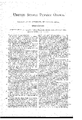
H. APPLEGATE. GRAIN DRIER. No. 293,133. a; Patented Feb. 5, 1884.
wnnnssns: 7 "INVENTOR:
wfiwyww in I V ATTORNEYS.
N. PETERS. Pholo'Litmgmplmr, WHSHIIIM 0.6.
T ciZZ whom, it may coltcern:
as rates PATENT rrrcn.
WVILLL-LM HEX-RY APPLEG-ATE, OF ATLANTIC, IO\VA.
l GRAIN DRIIER.
SPECIFICATION" forming part of Letters Patent No. 293,183, dated Felcruary 5, 1884.
Application filed June 14,1893. No model.)
Be it known that I, WILLIAM ll. Alumn- GATE, ofAtlantic, in the county of Cass and State of Iowa, have invented a new and I111- proved Grain-Drier, of which the following is a full, clear, and exact description.
The object of my invention is to provide a graindrying apparatus of simple construcapparatus, provision being also made for the escape of the moisture from the grain, and for the passage of air to be heated from below,
to ascend about the heatingpipes and grainpassages, and for the escape of any dust or grain -which may crowd through the wirescreen sidesof said passages, for maintaining a free air-inlet and promoting the perfect action of the apparatusas a whole, all as here'- inafterfully described and claimed.
Reference is to be had to'the accompanying drawings, forming part of this specification, in which similar letters of reference indicate corresponding parts in all the figures.
Figural is a sectional side elevation of my improved grain-drier, on the line 3 y, Fig. 2. Fig. 2 is a longitudinal sectional elevation on linear m, Fig. 1. Fig. 3 is a bottomview; and Fig. 4 is a sectional elevation, in part, of the heating apparatus on lines 2, Fig. 1.
I have here shown an example of my graindrying apparatus as constructed with two vertically-arranged grain-passages, but the number of passages, as also their length and width, may vary with therequired capacity.
(t represents the side and; end walls of; any suit-able inclosing case or: chamber, which walls may consist of metallined wood or brick, as desired, and depending on the capacity of the drier.
Within and free from walls 0,51 position the grain-passages I), which Ifix at-their tops preferably to the lower end of the feed-hopper a, by their end bars, I), the hopper-botton1 being fittedwith wood or metal plates or strips 7 c, inclining downwardto the open months or tops of passages b, as in Fig. 2, the bottoms of the passages I) being stayed in position by the casings of the graindischarge, valves, to be hereinafter described, and so that the pas,- sages I) will be held firmly and parallel with each other. I make the passages b with sides (I, of wire, of suitable mesh to retain the grain, the sides being spaced about an inch. apart, so as to holdthe grain in a thin layer, and the rough character of the sides (I, of open-mesh wires disposed vertically and horizontally, tends to retard the downward flow of the grain and prevents a tight packing of the. grain in the passages, keeping it much looser than would be possible with plain smooth walls of the passages, and so that the heat may have free access to all the kernels of grain for better drying effect thereon.
. To prevent a bulging out or collapsing of the side walls, d, so as to maintain an even thickness of the grain-passages for uniform drying effect, I propose to stay the I sides by rivets passed through the passages and head? ed at each end, or by the more desirable ar rangement of wires 0, which Ipass through the passages and down along their outer and opposite sides, using, preferably, a continuous wire, 6, interlacing the passages from top. to bottom, and spacing these wires 0 sidewise,
about six'inches apart, across the entire width I of the passages, thereby greatly strengthening the grain passages and assisting the wire sides in retarding the downward fiow of and tending to loosen the grain.
For effective readily-controllable valves, through which to discharge the driedgraiu frompassages b, I provide slide-valves f,which work .in slots cut or cast alongthe innerlower sides of the valve-casing g, which I make, preferably, in two partsywith a central joint, 71, along the bottom, so that the two side parts of the casin g can readily be slipped over the lower ends of the passages 12, and bolted or otherwise firmly secured thereto; and I flare the sides of casings g outward toward the bottom to admit of using wide valves f, having large apertures t, which may be brought to coincide with the apertures j of the bottoms of the casings-g, for discharge of the grain quickly when required, and by making the valve-casings g in two parts divided at h along the center of apertures j, I provide for casting the casings without cores,and cheaply,and so as to require little or no finish prior to adjustment on the passages b. I arrange the lower side edges of the casings 9 about one-half inch apart, as at k, to form inlets thereat for the air to be heated, and also to permit free discharge at the base of the drier, through passages It, for any dust or line grain which may escape through the wire-mesh sides of grainpassages 1), thereby maintaining a free air-inlet, and preventing a choking up of the apparatus, which might otherwise occur. The valvecasings 9 may be secured to the casing to at the back end, and should be otherwise supported between the discharge-apertures j at the bottom by suitable cross-bars fixed to or built in the casing a, for sustaining the loaded grain-passages Z, and relieving them of unnecessary strain.
To work the valves f, I connect them by rods Zwith straps of eccentrics m, fitted opposite the ends of the valves on a shaft, 11, to be turned by any suitable wheel or crank, 0, either slower or fast-er, to discharge the grain faster or slower, according to the time required in drying it; and the eccentrics m will preferably be set to work all the valves f of a drier simultaneously.
My improved heater for drying the grain in the passages Z1 consists of a series of verticallyranging hollow bars or pipes, p, connected by suitable nipples, q, with a lower transverse steam or other heatconveying pipe, 4', which is supported suitably in the side walls of case a, and has the heat-supply and exhaust pipes r a at opposite ends, the heads of pipes 99 being connected by the transverse support and stay p, about parallel with pipe 1'', which stay p may either be solid or have interior passages connecting pipes p with each other, said pipes 19 being located in front of and in line with the center of the spaces between the grain-passages I), so that the U-pipes s, ranging horizontally through the drier, will be held by their con necting-nipples t, along the sides (Z of grainpassages Z), said pipes .sbeing supported at their backs or bends s in any suitable sockets, 8 sustaining them vertically and against lat eral movement, so that the entire system of pipes s will be rigidly positioned across the drier, and at even distances (say one-half inch) from the sides (I of the grain-passages b, for uniform radiation of the heat to the grain in the passages.
I have here shown two U pipes 8 connecting with each vertical pipe 1) but the number of such pipes 8 may vary with the capacity of the drier-say from two to ten pairsas required. Vith a heater thus constructed a rapid even circulation of heat through all the pipes 8 may be secured and maintained.
At the front of the drier next the heater I cut an opening for a door, a, for access to the heater-pipes, which opening may be fitted with a sheet-metal plate, V, to form dead-air spaces for better confining the heat to the interior of the casing, which latter, if built of wood, may also be lined on its inner faces with sheet metal or any suilable non-conducter of heat, for safety against fire, and for economy of fuel. The head a of the casing a, or the casing itself, at or near the top, is fitted with apertures or pipes 10, for discharge of the steam andmoisture driven from the grain in drying, and said pipes 10 may be controlled by any suit able dampers, if desired.
In operation, the grain is fed to passages b from the hopper c as fast as it is discharged by the valves f below, which valves are worked by eccentrics m, to deliver the dried grain into a suitable hopper or pit, to be conveyed or elevated therefrom by any approved apparatus for transportation or storage. As the loose grain flows down through the thin passages Z1 it is acted upon by the air let in at passages and rising about and heated by the pipes s, which hot air reaches every kernel of the grain and quickly effects its thorough drying without burning or discoloration, thus leaving the grain in prime condition for market; and the operation of drying may be carried on continuously and with little practice on the part of the operator, thus giving a large capacity to an apparatus of moderate size and insuring a large output at comparatively small expense.
In practice, I may connect one or more suitable valve-controlled pipes to discharge steam into the drier in emergency of fire, to protect the drier or grain therein from injury or destruction from this cause; and I may also make the rods Z of valves f in two parts, connected by screw or other adjustable joints, so as to admit of adjusting the eccentrics and the discharge-orifices to more closely control the outflow of the dried grain from the passages b, as will readily be understood.
Having thus described my invention, what I claim as new, and desire to securc'by Letters Patent, is-
1. The combination, with the grain-passages b, having sides (I of intermeshing wires, of the continuous interlacing wires a, forming crossbars and surface-stays to the sides (I, substantially as shown and described.
2. The combination, with the grain-passages b, of the two-part valve-casings g, flared toward the bottom and centrally divided, and the valves f, substantially as shown and described.
3. The combination, with the grain-passages b and the flared casings g, apertured at j, of the valves f, apertured at '1', the rods Z, eccentrics m, and operating-shaft a, substantially as shown and described.
l. The combination, with the case a, grainpassages I), having sides at of intermeshing wires, valvesf, heating-pipes s, and passages 7c, of the moisture-outlets a, substantially as shown and described.
WILLIAM HENRY APPLEGATE, A
\Vitnesses:
D. T. CALLAWAY, A. M. \VAKEFIELD.
Publications (1)
| Publication Number | Publication Date |
|---|---|
| US293133A true US293133A (en) | 1884-02-05 |
Family
ID=2362320
Family Applications (1)
| Application Number | Title | Priority Date | Filing Date |
|---|---|---|---|
| US293133D Expired - Lifetime US293133A (en) | William ii |
Country Status (1)
| Country | Link |
|---|---|
| US (1) | US293133A (en) |
Cited By (3)
| Publication number | Priority date | Publication date | Assignee | Title |
|---|---|---|---|---|
| US2458356A (en) * | 1944-02-19 | 1949-01-04 | Socony Vacuum Oil Co Inc | Method and apparatus for burning contaminants from a moving bed contact mass |
| US9359044B2 (en) | 2013-10-10 | 2016-06-07 | Jacob Willem Langelaan | Weight-shift controlled personal hydrofoil watercraft |
| USD843303S1 (en) | 2016-07-08 | 2019-03-19 | MHL Custom, Inc. | Hydrofoil board |
-
0
- US US293133D patent/US293133A/en not_active Expired - Lifetime
Cited By (4)
| Publication number | Priority date | Publication date | Assignee | Title |
|---|---|---|---|---|
| US2458356A (en) * | 1944-02-19 | 1949-01-04 | Socony Vacuum Oil Co Inc | Method and apparatus for burning contaminants from a moving bed contact mass |
| US9359044B2 (en) | 2013-10-10 | 2016-06-07 | Jacob Willem Langelaan | Weight-shift controlled personal hydrofoil watercraft |
| US9586659B2 (en) | 2013-10-10 | 2017-03-07 | Jacob Willem Langelaan | Powered hydrofoil board |
| USD843303S1 (en) | 2016-07-08 | 2019-03-19 | MHL Custom, Inc. | Hydrofoil board |
Similar Documents
| Publication | Publication Date | Title |
|---|---|---|
| US293133A (en) | William ii | |
| US312341A (en) | duryea | |
| US1028899A (en) | Grain-drier. | |
| US2333089A (en) | Grain drier | |
| US618508A (en) | Apparatus for drying and cooling grain | |
| US339874A (en) | Grain-drier | |
| US663418A (en) | Grain-drier. | |
| US172398A (en) | Improvement in fruit-driers | |
| US923137A (en) | Grain-drier. | |
| US128521A (en) | Improvement in fruit-driers | |
| US313982A (en) | Haedt | |
| US1282960A (en) | Grain-drier. | |
| US268587A (en) | Machine for drying | |
| US403411A (en) | Grain-drier | |
| US278890A (en) | Chaeles a | |
| US209589A (en) | Improvement in grain-driers | |
| US508113A (en) | Fruit-drier | |
| US133060A (en) | Improvement in fruit-driers | |
| US154930A (en) | Improvement in drying-machines | |
| US1067411A (en) | Drying plant. | |
| US256615A (en) | Fruit-drier | |
| US1420144A (en) | Drier | |
| US1089027A (en) | Evaporator. | |
| US637307A (en) | Lumber-drier. | |
| US361126A (en) | borland |