US2927770A - Grain car door opener - Google Patents
Grain car door opener Download PDFInfo
- Publication number
- US2927770A US2927770A US668191A US66819157A US2927770A US 2927770 A US2927770 A US 2927770A US 668191 A US668191 A US 668191A US 66819157 A US66819157 A US 66819157A US 2927770 A US2927770 A US 2927770A
- Authority
- US
- United States
- Prior art keywords
- door
- back frame
- frame
- arm
- pit
- Prior art date
- Legal status (The legal status is an assumption and is not a legal conclusion. Google has not performed a legal analysis and makes no representation as to the accuracy of the status listed.)
- Expired - Lifetime
Links
Images


Classifications
-
- B—PERFORMING OPERATIONS; TRANSPORTING
- B61—RAILWAYS
- B61J—SHIFTING OR SHUNTING OF RAIL VEHICLES
- B61J1/00—Turntables; Traversers; Transporting rail vehicles on other rail vehicles or dollies
- B61J1/10—Traversers
Definitions
- One such type is characterized by an opening frame, mounted on a rocking arm, with the frame engaging the outer surface of the door, which by exerting pressure thereagainst, swings the door inwardly and upwardly into the interior of the car.
- the primary object of the present invention is to provide a superior door opener of this general type.
- a further object of this invention' is to provide 'a door opener of rugged construction that is capable of exerting
- a still further object of this invention is to provide a pit-mounted door opener having a cooperating cover plate for closing the pit opening in accordance with the operating movements of the opening mechanism so as to eliminate the hazards otherwise present.
- FIG. 1 is a perspective view showing a grain car door opener embodying the present invention
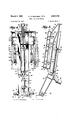
- Figure 2 is a side elevational view of the door opener -of Fig. 1 illustrated in full lines in its inoperative position and in broken lines in its initial door engaging position in readiness for operating on the door,
- Figure 3 is a view similar to Fig. 2 but with the various movable parts of the mechanism shown in two operative positions,
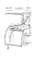
- Figure'4' is an outer elevational view of the device illustrated in Fig. 1,
- Figure 5 is a longitudinal sectional view taken on line plate showing the method of connecting the guide bar to the, plate
- Figure 11 is a partial top plan view of the pit cover plate illustrated in Fig. 10.
- reference character 20 designates in general a door opener embodying the present invention.
- a grain car 21 is positioned along the side of the door opener 20 with its side opening in align ment therewith.
- the outer door 22 is shown rolled back to expose the inner plank door 24 on which the door opener operates.
- the door opener 20, as best shown in Figs. 2 and 3, may be mounted in a pit 25 located below a work platform 26 extending parallel with the tracks 28 on which the car 21 is spotted.
- the bottom of the pit is provided with a mounting base 29 preferably constructed from structural steel shapes.
- Rigidly connected to the base29 at the forward end of the pit, that is, the end nearest to the rails 28, is a pair of spaced journal bearings 30 aligned parallel with the tracks 28.
- a carrier arm 32 is connected to the bearings 30 by means of a journal shaft 34 extending through the base of the arm. It will be seen that this connection permits a pivotal or rocking motion of the arm about an axis parallel to the tracks 28.
- the arm 32 is a hollow box or shell type construction fabricated principally from pieces cut from flat stock. Its upper portion is bifurcatedto form a lengthwise notch 35, Fig. 4, and two similar branches or forks 36. Centrally located at the base of the notch 35,
- a lug 38 formed wit an opening therethrough.
- the extreme top portion of the two similar arm branches 36 are provided with forwardly extending knuckles 39, each having two spaced side members 40 provided with aligned holes.
- the side pieces 40 are built up to an increased thickness so that the holes therethrough provide substantial bearing surfaces for a pivotal connection hereinafterdescribed.
- a forked lug 41 rigidly attached to the arm and having an opening therethrough.
- Pressure fluid actuated means are provided for rotatin the arm 32 about its base axis.
- this means is shown to take the form of a ram type fluid motor 42 having a piston rod 44 and connected bc tween the arm 32 and the abutment bracket 31.
- the fluid motor 42 is pivotally connected at its base to the abutment bracket 31 by means of a pin 45 inserted through openings in the base of the fluid motor and the openings in the abutment bracket and held in place by means of cotters 46, while the piston rod is pivotally connected to the lug 41 by means of a pin 48 inserted through the openings in the lug and the opening in the rod and held in place by cotters 49.
- Pressure fluid is supplied to the motor 42 in a conventional mannerby supply lines 50.
- the back frame is principally a weldment of channel members and fiat stock.
- Two longitudinally extending channeLmembers 52 with inwardly directed flanges constitute its side edges.
- Two other longitudinally extending channel members 54 are placed intermediate the side channels 5'2 and are spaced symmetrically about the longitudinal axis of the frame with their flanges directed outwardly.
- These longitudinally'disposed channel members 52 and54 are integral members extendingthe'full length of the back frame.
- Two longitudinally aligned guide bars 53 whose purpose will hereinafter appear, are rigidly fixed on the outer side to the top and bottom portions, respectively, of each side channel member 52.
- a flat plate 60 provided with two longitudinally extending slots 61 located symmetricallyabout its longitudinal axis, covers the front face of the back frame 51.
- plate portions 62 and'63 cover the space between the members 55 and 56 and '58 and'59, respectively, while the space between the longitudinal members 58- -58 is covered by a third plate portion 64.
- This particular construction leaves open pockets 65, Figs. 1 and 4, on both sides of the back frame with the top of the cross channel member 56 forming the bottoms.thereof.
- Each pocket is provided with v a lug 66 rigidly connected to the member 56 and provided with an opening therethrough.
- the back frame 51 is hingedly connected to the carrier arm 32 along an upper axis disposed substantially parallel to the longitudinal axisof the car 21, as by means of lugs cooperating with the knuckles 39 of the carrier arm.
- these lugs consist of apertured bushings 69 welded to plates 70 which extend through the top channel member 58 of the back frame. to the cross member 59.
- the hinged connection is formed by fitting the bushingsbetweentheside pieces of, the knuckles 39 and inserting a pin 71, held in place by washers 73 and cottersfl t, through the openings in the side pieces 40 and bnshing170.
- a lever arm 75 Extending centrally from the top portion of the back frame 51 is a lever arm 75 inclinedbackwardly. so as to, be positioned directly above the notch 35 of the, carrier arm Blandbetween the branches 36 thereof. As shown,
- the lever arm is composed of two spaced members 76 extendingdown through the top portion of the back frame to the cross members 59 and positioned in abutting relationship with the longitudinal channel members 54, as shown in Fig. 7, to which they may be welded.
- a top plate 78 and a bottom plate 79, Fig. 5, may be welded between the members 7676 to strengthen the lever arm.
- the members 76 are provided at their outer ends with apertured bushings. 80 welded thereto to provide a suitable means for achieving a pivotal connection hereinafter described.
- Pressure fluid means are provided for swinging the back frame relative to the carrier arm.
- this. means is shown to consist of a ram type fiuidmotor 81, disposed within the notch 35 of the carrier arm, pivotally connected at its base to the lug 38.by means of a pin 82 and ,pivotally connected to the lever. arm .75 by means of a pin 84 inserted througlrthe bushings 80 andthe. head of its pistonrod 35. fitted there-
- The, pin 84 may be held in place in a conventional manner by washers 86 and cotters 88. Pressure fluid may be supplied to the fluid motor 81 in a conventional manner through the use of supply lines 89.
- a plate 96 along both side margins of which are provided a plurality of spaced outwardly protruding spikes 98, covers the entire front of the door engaging frame.
- the spikes 98 serve to penetrate the inner plank door andto thus provide a positive engagement between the latter and the door engaging frame during operation of the opener.
- the door engaging frame 90 also includes two backwardly extending lugs 103 rigidly connected to it and symmetrically disposed on opposite sides of said frame. As shown in Fig. 9, the lugs 103 may be fitted between and welded to two of the spaced cross members -95 of the door engaging frame 90.
- the slots 61 in the cover plate 60 of the back frame accommodate the lugs. 103 which extend therethrough.
- pressure fluid actuated means which, as shown in the present example, may take the form of two ram type fluid motors 105, each disposed in one of the pockets 65 0f the back frame and connected at its base to a lug 66 by a pin 108 and at the end of its piston rod 106 to a lug 103 by a pin 109.
- Pressure fluid may be supplied to the motors 105, according to conventionalpractice, by supply lines 110.
- the opener may be provided with a pit cover for closing the same in accordance with the operating movement of the arm.
- two laterally aligned guide brackets 111 are connected to, the two back surfaces of the carrier arm 32, at a height corresponding to the top of the pit opening, with their flat bottoms facing outwardly and spaced from the arm.
- a cover plate 112 as shown in Figs. 1 and 11, cut away at its forward edge to form a notch therein, is provided with a rod 114 cottered, or otherwise attached, to it and extending across the notch.
- the rod is assembled to, the cover plate by first being fitted between the guide brackets 111 and the, carrier arm 32 so that the plate will be connected to, and subject to the movements of, the carrier arm.
- the plate 112 is supported against vertical movement by the margins of the pit opening and is of suflicient size to completely cover the opening when the carrier arm 32 is. in its foremost position.
- the operation of the door opener may be briefly stated. With the opener in its normal retracted or inoperative position, as shown by he solid lines in Fig. 2, the cycle of operation is begun by applying pressure fluid to the base end of the fluid motor 42 causing the carrier arm 32 to be moved towards the box car 21 by extension teams 7 of the piston rod 44. As the arm approaches the door pressure fluid is applied to the upper end of the fluid motor 81 to retract the rod and swing the back frame 51 and the door engaging frame 90 into parallel relationship with the inner door 24. Pressure fluid is then applied to the upper ends of the fluid motors 105 to lower thedoor engaging frame 90 so that its bottom edge is brought down to the car floor. The position of the opener at this point is illustrated by the broken lines of Fig. 2. Additional pressure fluid is then applied to the upper end of the fluid motor 8 1 to drive the spikes 98 into the door, and the door inwardly against the grain. In the event the inner door is nailed to the posts of the car opening, the door should, of
- the opener is then moved to the position shown by the broken lines of Fig. 3 by applying additional pressure fluid to the base end of the fluid motor 42 to cause the top of the arm 32 to move toward and into the car, and by simultaneously or subsequently applying additional pressure fluid to the upper end of the fluid motor 81 causing the back frame 5 1 and the door engaging frame 90 to be swung upwardly through the grain into the interior-of the car to a level near the top of the grain.
- the opening mechanism may be returned to its normal retracted position by reversing the fluid pressures applied to the fluid motors in the opening operation.
- a grain car door opener comprising an upstanding carrier arm pivotally supported at its base for movement about a horizontal axis and having a lengthwise notch formed in its upper portion, a rectangular back frame pivoted adjacent its upper portion to the upper portion of said carrier arm for movement about an upper axis parallel to said base axis and having a lever arm extending upwardly from said upper portion, a door engaging frame slidably carried by and forwardly of said back frame for movement relative thereto in a direction normal to said upper axis, a fluid motor having one end connected to said door engaging frame and the other end connected to said back frame for moving said door engaging frame relative to the back frame, a fluid motor disposed in said lengthwise notch having one end pivotally connected to the base of said notch and the other end pivotally connected to said lever arm for swinging said back frame relative to said carrier arm about said upper axis, and a fluid motor cooperating with said carrier arm to swing the latter about its base axis.
- a grain car door opener comprising an upstanding carrier arm pivotally supported at its base for movement about a horizontal axis and having its top portion bifurcated to form two similar spaced branches, a rectangular back frame pivoted adjacent its upper portion to the upper portion of said carrier arm for movement about a 6 an upper axis parallel with said base axis and having "a lever arm extending upwardly andback'wardly from said upper portion, guide bars rigidly connected to and parallel with the side edges of said back' frame, a door engaging frame slidably supported on said back'frame by guides rigidly connected to said door engaging frame and cooperating with said guide bars, said door engaging frame having portions disposed forwardly of I said back frame for engaging the door and maintaining the same in spaced relationship with said back frame during such engagement, two backwardly extending lugs rigidly connected to the back of said door engaging frame and symmetrically disposed on opposite sides of the-longitudinal axis of the latter, two fluid motors associated one with each of said lugs with each motor having one end connected to its
- a grain car door opener comprising a pit, an upstanding carrier arm pivotally supported at its base in said pit and having an upper portion extending from the top of said pit, a flat plate-supported by the margins of said pit and of suflicient area to completely cover the pit when said carrier arm is in its foremost position, a guide bracket attached to the back of said carrier arm at a level corresponding to the top of said pit, and means connecting said guide bracket to the forward edge of said flat plate so that the latter is moved over the'pit opening in accordance with the movement of said carrier arm.
- a grain car door opener comprising a pit, an upstanding carrier arm pivotally supported at its base in said pit and having an upper portion extending from the top of said pit, a guide bracket shaped in the form of a flat bottomed U connected to the back surface of said carrier arm at a height corresponding to the top of the pit, said bracket being positioned with its flat bottom facing outwardly so as to be spaced from said arm, a cover plate supported by the margins of said pit and cut away at its forward edge to form a notch therein, and a rod connected to the cover plate, said rod extending across the notch and being fitted between said guide bracket and said carrier arm so as to be attached to and subject to the move ments of the latter.
- a grain car door opener comprising a pit, an upstanding carrier arm pivotally supported at its base for movement about a horizontal axis in said .pit, said arm having an upper portion extending above the top of said pit trough an opening therein, said upper portion being formed with a centrally disposed lengthwise notch, a rectangular back frame pivoted adjacent its upper portion to the extreme top end of said carrier arm about an upper axis parallel with said base axis and having a lever arm extending upwardly and backwardly from said upper portion, a door engaging frame slidably carried by and forwardly of said back frame for movement in a direction normal to said upper axis, two backwardly extending lugs rigidly connected to the back of said opening frame symmetrically and disposed on opposite sides of the longitudinal axis of the latter, two jointly operating fluid motors associated one with each of said lugs with each motor having one end pivotally connected to its respective lug and the other end pivotally connected to said back frame for moving said door engaging frame relative to the back frame, a fluid
- a grain car door opener comprising an upstanding carrier aim supported at its base for movement away from or toward the door of a car spotted alongside said opener, a back frame having the upper portion thereof pivotally connected to, the upper end of said carrier armfor rotation about an upper axis substantially paral lel to the longitudinal axis of the car, a door engaging frame slidably carried by said back frame for movement relative thereto, in a direction normal to said upper axis, said door engaging frame having portions disposed outwardly from said back frame in a direction toward the car door for engaging the door and maintaining the same in spaced relationship with said back frame during such engagement, fluid motor means operating with said carrier arm for moving the latter relative to the car, fluid motor means cooperating with said carrier arm and said back frame for pivotally rotating the back frame relative to the carrier arm, and fluid motor means cooperating with said back frame and said door engaging frame for sliding the door engaging frame relative to the back frame.
- a grain car door opener comprising a pit, an upstanding carrier: arm having a bottom portion positioned in said pit and an upper portion extending up wardly from the top of said pit, means pivotally mounting said bottom portion adjacent the lower end thereof formovement of said upper portion away from or toward the'door of a car spotted alongside said pit, a flat plate supported by the margins of said pit and of suffi'- cient area to completely cover said pit when said carrier arm is in its foremost operating position, a guide bracket attached'to the back of the carrier arm at a level corresponding to the top of said pit, means connecting said guide bracket to the forward edge of said flat plate so that the latter is moved over the pit opening in accordance with the movement of said carrier arm, a back frame having an upper portion pivotally connected to the upper portion of said carrier arm for rotative movement of said back frame about an upper axis substantially parallel to the longitudinal axis of the car, a door engaging frame slidably carried by and forwardly of said back frame for movement relative to said back frame in a direction normal
Landscapes
- Engineering & Computer Science (AREA)
- Transportation (AREA)
- Mechanical Engineering (AREA)
- Automobile Manufacture Line, Endless Track Vehicle, Trailer (AREA)
Description
GRAIN CAR DOOR OPENER Filed June 26, 1957 6 Sheets-Sheet 2 March 8, 1960 w. E. ERICKSON E L 2,927,770
GRAIN CAR DOOR OPENER 6 Sheets-Sheet 3 Filed June 26, 1957 March 8, 1960 w. E. ERICKSON ETA!- 2,927,770
GRAIN CAR DOOR OPENER 6 Shets-Sheet 4 Filed June 26, 1957 March 8, 1960 W. E. ERICKSON ETAL GRAIN CAR DOOR OPENER 6 Sheets-Sheet 5 Filed June 26, 1957 March 8, 1960 w. E. ERICKSON ETAL GRAIN CAR DOOR OPENER 6 Sheets-Sheet 6 Filed June 26, 1957 United stat Patent 1 t,
GRAIN CAR noon OPENER Willard E. Erickson, Chicago, Albert Musschoog'lark Ridge, and Frank M. Grayson, Chicago, llL, assignors to Link-Belt Company, a corporation of Illinois Application June 26, 1957, Serial No. 668,191
7 Claims. (Cl. 254-84) Railroad box cars used for shipping grain, or other 7 similar material, in bulk are provided when loaded with inner doors to prevent spillage from the cars during loading and in transit. Usually, these doors comprise a number of abutting planks or boards placed across the car door posts, and either nailed to the posts or held in place only by the pressure of the loaded grain. Also, inner doors made of several layers of heavy paper reinforced with steel straps nailed to the door posts and spanning the door opening, with one board at the top and one board at the bottom of the door, have been employed to a limited extent. Most unloading operations, of course,
necessitate removal of these doors from the cars prior .to discharging the grain.
Heretofore various types of devices have been developed for removing inner doors by mechanical means.
One such type is characterized by an opening frame, mounted on a rocking arm, with the frame engaging the outer surface of the door, which by exerting pressure thereagainst, swings the door inwardly and upwardly into the interior of the car. The primary object of the present invention is to provide a superior door opener of this general type.
A further object of this invention'is to provide 'a door opener of rugged construction that is capable of exerting,
without danger of breakage, the high pressures required for moving the door through the backed-up grain.
A still further object of this invention is to provide a pit-mounted door opener having a cooperating cover plate for closing the pit opening in accordance with the operating movements of the opening mechanism so as to eliminate the hazards otherwise present.
Other objects and advantages of the invention will be apparent during the course of the following description. In the accompanying drawings forming a part of this specification and in which like reference characters are employed to designate like parts throughout the same,
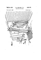
Figure 1 is a perspective view showing a grain car door opener embodying the present invention,
Figure 2 is a side elevational view of the door opener -of Fig. 1 illustrated in full lines in its inoperative position and in broken lines in its initial door engaging position in readiness for operating on the door,
Figure 3 is a view similar to Fig. 2 but with the various movable parts of the mechanism shown in two operative positions,
Figure'4'is an outer elevational view of the device illustrated in Fig. 1,
Figure 5 is a longitudinal sectional view taken on line plate showing the method of connecting the guide bar to the, plate, and Figure 11 is a partial top plan view of the pit cover plate illustrated in Fig. 10. In the drawings, wherein for the purpose of illustration is shown a preferred embodiment of the invention, and first particularly referring to Fig. 1, reference character 20 designates in general a door opener embodying the present invention. A grain car 21 is positioned along the side of the door opener 20 with its side opening in align ment therewith. The outer door 22 is shown rolled back to expose the inner plank door 24 on which the door opener operates.
The door opener 20, as best shown in Figs. 2 and 3, may be mounted in a pit 25 located below a work platform 26 extending parallel with the tracks 28 on which the car 21 is spotted. The bottom of the pit is provided with a mounting base 29 preferably constructed from structural steel shapes. Rigidly connected to the base29 at the forward end of the pit, that is, the end nearest to the rails 28, is a pair of spaced journal bearings 30 aligned parallel with the tracks 28. To the rear of the bearings 30, and centered between them, is an abutment bracket 31 attached to the base 29 and provided with an opening in its upper portion.
A carrier arm 32 is connected to the bearings 30 by means of a journal shaft 34 extending through the base of the arm. It will be seen that this connection permits a pivotal or rocking motion of the arm about an axis parallel to the tracks 28.
Preferably, the arm 32 is a hollow box or shell type construction fabricated principally from pieces cut from flat stock. Its upper portion is bifurcatedto form a lengthwise notch 35, Fig. 4, and two similar branches or forks 36. Centrally located at the base of the notch 35,
and rigidly connected thereto, is a lug 38 formed wit an opening therethrough. As best shown in Fig. 6, the extreme top portion of the two similar arm branches 36 are provided with forwardly extending knuckles 39, each having two spaced side members 40 provided with aligned holes. Preferably the side pieces 40 are built up to an increased thickness so that the holes therethrough provide substantial bearing surfaces for a pivotal connection hereinafterdescribed. On the back of the arm, below the base of the notch 35, is provided a forked lug 41 rigidly attached to the arm and having an opening therethrough. Pressure fluid actuated means are provided for rotatin the arm 32 about its base axis. In the present instance this means is shown to take the form of a ram type fluid motor 42 having a piston rod 44 and connected bc tween the arm 32 and the abutment bracket 31. Preferably, the fluid motor 42 is pivotally connected at its base to the abutment bracket 31 by means of a pin 45 inserted through openings in the base of the fluid motor and the openings in the abutment bracket and held in place by means of cotters 46, while the piston rod is pivotally connected to the lug 41 by means of a pin 48 inserted through the openings in the lug and the opening in the rod and held in place by cotters 49. Pressure fluid is supplied to the motor 42 in a conventional mannerby supply lines 50. v V
A rectangular back frame 51 is pivotally connected I adjacent its upper edge to the top of the carrier arm 32 between.
shown by Figs. 4,5 and 7, wherein it is noted that the back frame is principally a weldment of channel members and fiat stock. Two longitudinally extending channeLmembers 52 with inwardly directed flanges constitute its side edges. Two other longitudinally extending channel members 54 are placed intermediate the side channels 5'2 and are spaced symmetrically about the longitudinal axis of the frame with their flanges directed outwardly. These longitudinally'disposed channel members 52 and54are integral members extendingthe'full length of the back frame. Two longitudinally aligned guide bars 53, whose purpose will hereinafter appear, are rigidly fixed on the outer side to the top and bottom portions, respectively, of each side channel member 52.
An integral channel member 55, Fig. 5, extends along and forms the bottom edge of the back frame. Spaced above and parallel with the bottom channel is a crosschannel 56 divided into three segments fitted and welded between the longitudinal members 52- and 54-. The flanges of thismember 56 are directed downward towards the bottom channel 55 so as to provide a flat top surface; Thetop edge of the back frame is comprised of a channel member 58 segmented to fit between the various elements protruding from it. Spaced below and parallel with the top channel 58 is the cross channel member 59-segmented into three parts and fitted between the longitudinal members 52 and 54.
A flat plate 60, provided with two longitudinally extending slots 61 located symmetricallyabout its longitudinal axis, covers the front face of the back frame 51. In the rear portion of the back frame, plate portions 62 and'63 cover the space between the members 55 and 56 and '58 and'59, respectively, while the space between the longitudinal members 58- -58 is covered by a third plate portion 64. This particular construction leaves open pockets 65, Figs. 1 and 4, on both sides of the back frame with the top of the cross channel member 56 forming the bottoms.thereof. Each pocket is provided with v a lug 66 rigidly connected to the member 56 and provided with an opening therethrough.
The back frame 51 is hingedly connected to the carrier arm 32 along an upper axis disposed substantially parallel to the longitudinal axisof the car 21, as by means of lugs cooperating with the knuckles 39 of the carrier arm. Preferably, these lugs consist of apertured bushings 69 welded to plates 70 which extend through the top channel member 58 of the back frame. to the cross member 59. The hinged connection is formed by fitting the bushingsbetweentheside pieces of, the knuckles 39 and inserting a pin 71, held in place by washers 73 and cottersfl t, through the openings in the side pieces 40 and bnshing170.
. Extending centrally from the top portion of the back frame 51 is a lever arm 75 inclinedbackwardly. so as to, be positioned directly above the notch 35 of the, carrier arm Blandbetween the branches 36 thereof. As shown,
the lever arm is composed of two spaced members 76 extendingdown through the top portion of the back frame to the cross members 59 and positioned in abutting relationship with the longitudinal channel members 54, as shown in Fig. 7, to which they may be welded. A top plate 78 and a bottom plate 79, Fig. 5, may be welded between the members 7676 to strengthen the lever arm. Preferably, the members 76 are provided at their outer ends with apertured bushings. 80 welded thereto to provide a suitable means for achieving a pivotal connection hereinafter described.
Pressure fluid means are provided for swinging the back frame relative to the carrier arm. In the present instance, this. means is shown to consist of a ram type fiuidmotor 81, disposed within the notch 35 of the carrier arm, pivotally connected at its base to the lug 38.by means of a pin 82 and ,pivotally connected to the lever. arm .75 by means of a pin 84 inserted througlrthe bushings 80 andthe. head of its pistonrod 35. fitted there- The, pin 84 may be held in place in a conventional manner by washers 86 and cotters 88. Pressure fluid may be supplied to the fluid motor 81 in a conventional manner through the use of supply lines 89.
A door engaging frame 90 is slidably carried by the back frame 51 for vertical movement away from or toward the top of the carrier arm 32 in a plane forwardly of and parallel to that of the back frame. As shown in Figs. 5 to 8, this frame may be constructed essentially from channel members. In the presently illustrated embodiment, two longitudinally extending channelmembers 91 extend along and form the side, edges,,while a channel member 92 and an angle member 94 form the bottom and top edges, respectively, of the frame 90. A series of spaced cross channel members 95, Fig. 5, placed parallel with said bottom and top edges adds further strength to the frame. A plate 96, along both side margins of which are provided a plurality of spaced outwardly protruding spikes 98, covers the entire front of the door engaging frame. The spikes 98 serve to penetrate the inner plank door andto thus provide a positive engagement between the latter and the door engaging frame during operation of the opener.
As shown in the present instance, the support between the back frame 51 and the door engaging frame 90 may be obtained by employing the two aligned guide bars 53 rigidly connected to each of the side channels 52 and a female guide member 100 for each guide bar attached to the side channels 91 of the door engaging frame by meansof a right angle bracket 101 and bolts 102, as best shown'in Figs. 4, 6 and 7.
The door engaging frame 90 also includes two backwardly extending lugs 103 rigidly connected to it and symmetrically disposed on opposite sides of said frame. As shown in Fig. 9, the lugs 103 may be fitted between and welded to two of the spaced cross members -95 of the door engaging frame 90. The slots 61 in the cover plate 60 of the back frame accommodate the lugs. 103 which extend therethrough.
Relative movement between the door engaging frame 90 and the back frame 51, is obtained by pressure fluid actuated means, which, as shown in the present example, may take the form of two ram type fluid motors 105, each disposed in one of the pockets 65 0f the back frame and connected at its base to a lug 66 by a pin 108 and at the end of its piston rod 106 to a lug 103 by a pin 109. Pressure fluid may be supplied to the motors 105, according to conventionalpractice, by supply lines 110.
To prevent injury to a workman who might otherwise fall into the pit opening through which the carrier arm 32 extends, the opener may be provided with a pit cover for closing the same in accordance with the operating movement of the arm. To provide such acooperating cover, two laterally aligned guide brackets 111, each shaped in the form of a flat bottomed U, are connected to, the two back surfaces of the carrier arm 32, at a height corresponding to the top of the pit opening, with their flat bottoms facing outwardly and spaced from the arm. A cover plate 112, as shown in Figs. 1 and 11, cut away at its forward edge to form a notch therein, is provided with a rod 114 cottered, or otherwise attached, to it and extending across the notch. The rod is assembled to, the cover plate by first being fitted between the guide brackets 111 and the, carrier arm 32 so that the plate will be connected to, and subject to the movements of, the carrier arm. The plate 112 is supported against vertical movement by the margins of the pit opening and is of suflicient size to completely cover the opening when the carrier arm 32 is. in its foremost position.
The operation of the door opener may be briefly stated. With the opener in its normal retracted or inoperative position, as shown by he solid lines in Fig. 2, the cycle of operation is begun by applying pressure fluid to the base end of the fluid motor 42 causing the carrier arm 32 to be moved towards the box car 21 by extension teams 7 of the piston rod 44. As the arm approaches the door pressure fluid is applied to the upper end of the fluid motor 81 to retract the rod and swing the back frame 51 and the door engaging frame 90 into parallel relationship with the inner door 24. Pressure fluid is then applied to the upper ends of the fluid motors 105 to lower thedoor engaging frame 90 so that its bottom edge is brought down to the car floor. The position of the opener at this point is illustrated by the broken lines of Fig. 2. Additional pressure fluid is then applied to the upper end of the fluid motor 8 1 to drive the spikes 98 into the door, and the door inwardly against the grain. In the event the inner door is nailed to the posts of the car opening, the door should, of
course, be pushed a sufficient distance inwardly to free" the nails from the posts.
With the spikes firmly set in the door, pressure fluid is applied to the base ends of the fluid motors 105 to move the door engaging frame, and the door, upwardly in respect to the back frame. This position is shown illustrated by the full lines of Fig. 3. The opener is then moved to the position shown by the broken lines of Fig. 3 by applying additional pressure fluid to the base end of the fluid motor 42 to cause the top of the arm 32 to move toward and into the car, and by simultaneously or subsequently applying additional pressure fluid to the upper end of the fluid motor 81 causing the back frame 5 1 and the door engaging frame 90 to be swung upwardly through the grain into the interior-of the car to a level near the top of the grain. When desired, the opening mechanism may be returned to its normal retracted position by reversing the fluid pressures applied to the fluid motors in the opening operation.
Means for controlling the operation of the fluid motors are well known in the art and consequently are not made a part of the present invention. However, it is thought preferable that these controls be located at some adjacent point, such as the control station 115, illustrated in Fig. 1, from which the operation of the opener may be closely observed.
It is to be understood that the form of this invention herewith shown and described is to be taken as a preferred example of the same, and that various changes in the shape, size and arrangement of parts may be resorted to without departing from the spirit of the invention or the scope of the subjoined claims.
Having thus described the invention, we claim:
1. A grain car door opener comprising an upstanding carrier arm pivotally supported at its base for movement about a horizontal axis and having a lengthwise notch formed in its upper portion, a rectangular back frame pivoted adjacent its upper portion to the upper portion of said carrier arm for movement about an upper axis parallel to said base axis and having a lever arm extending upwardly from said upper portion, a door engaging frame slidably carried by and forwardly of said back frame for movement relative thereto in a direction normal to said upper axis, a fluid motor having one end connected to said door engaging frame and the other end connected to said back frame for moving said door engaging frame relative to the back frame, a fluid motor disposed in said lengthwise notch having one end pivotally connected to the base of said notch and the other end pivotally connected to said lever arm for swinging said back frame relative to said carrier arm about said upper axis, and a fluid motor cooperating with said carrier arm to swing the latter about its base axis.
2. A grain car door opener, comprising an upstanding carrier arm pivotally supported at its base for movement about a horizontal axis and having its top portion bifurcated to form two similar spaced branches, a rectangular back frame pivoted adjacent its upper portion to the upper portion of said carrier arm for movement about a 6 an upper axis parallel with said base axis and having "a lever arm extending upwardly andback'wardly from said upper portion, guide bars rigidly connected to and parallel with the side edges of said back' frame, a door engaging frame slidably supported on said back'frame by guides rigidly connected to said door engaging frame and cooperating with said guide bars, said door engaging frame having portions disposed forwardly of I said back frame for engaging the door and maintaining the same in spaced relationship with said back frame during such engagement, two backwardly extending lugs rigidly connected to the back of said door engaging frame and symmetrically disposed on opposite sides of the-longitudinal axis of the latter, two fluid motors associated one with each of said lugs with each motor having one end connected to its respective lug and the other end connected to said back frame for moving said door engaging frame relative to the back frame, a fluid motor disposed between said two branches of said carrier arm and having one end pivotally connected to saidcarrier arm and the other end pivotally connected to said lever arm for swinging said back frame relative to said carrier arm about said upper axis, and a fluid motor cooperating with said carrier arm to swing the latter about said base axis. v 3. In a grain car door opener, the combinationcomprising a pit, an upstanding carrier arm pivotally supported at its base in said pit and having an upper portion extending from the top of said pit, a flat plate-supported by the margins of said pit and of suflicient area to completely cover the pit when said carrier arm is in its foremost position, a guide bracket attached to the back of said carrier arm at a level corresponding to the top of said pit, and means connecting said guide bracket to the forward edge of said flat plate so that the latter is moved over the'pit opening in accordance with the movement of said carrier arm.
4. In a grain car door opener, the combination comprirsing a pit, an upstanding carrier arm pivotally supported at its base in said pit and having an upper portion extending from the top of said pit, a guide bracket shaped in the form of a flat bottomed U connected to the back surface of said carrier arm at a height corresponding to the top of the pit, said bracket being positioned with its flat bottom facing outwardly so as to be spaced from said arm, a cover plate supported by the margins of said pit and cut away at its forward edge to form a notch therein, and a rod connected to the cover plate, said rod extending across the notch and being fitted between said guide bracket and said carrier arm so as to be attached to and subject to the move ments of the latter.
5. A grain car door opener, comprising a pit, an upstanding carrier arm pivotally supported at its base for movement about a horizontal axis in said .pit, said arm having an upper portion extending above the top of said pit trough an opening therein, said upper portion being formed with a centrally disposed lengthwise notch, a rectangular back frame pivoted adjacent its upper portion to the extreme top end of said carrier arm about an upper axis parallel with said base axis and having a lever arm extending upwardly and backwardly from said upper portion, a door engaging frame slidably carried by and forwardly of said back frame for movement in a direction normal to said upper axis, two backwardly extending lugs rigidly connected to the back of said opening frame symmetrically and disposed on opposite sides of the longitudinal axis of the latter, two jointly operating fluid motors associated one with each of said lugs with each motor having one end pivotally connected to its respective lug and the other end pivotally connected to said back frame for moving said door engaging frame relative to the back frame, a fluid motor disposed in said lengthwise notch having one end pivotally connected to the base of said notch and the other end pivotally connected to said lever arm for swinging said back frame reltive to said carrier arm, an abutment bracket mounted in said pit, and a fluid motor having one end pivotally connected to said carrier arm and the other end ,pivotally connected to said abutment, bracket for swinging said arm about said base axis,
6. A grain car door opener, comprising an upstanding carrier aim supported at its base for movement away from or toward the door of a car spotted alongside said opener, a back frame having the upper portion thereof pivotally connected to, the upper end of said carrier armfor rotation about an upper axis substantially paral lel to the longitudinal axis of the car, a door engaging frame slidably carried by said back frame for movement relative thereto, in a direction normal to said upper axis, said door engaging frame having portions disposed outwardly from said back frame in a direction toward the car door for engaging the door and maintaining the same in spaced relationship with said back frame during such engagement, fluid motor means operating with said carrier arm for moving the latter relative to the car, fluid motor means cooperating with said carrier arm and said back frame for pivotally rotating the back frame relative to the carrier arm, and fluid motor means cooperating with said back frame and said door engaging frame for sliding the door engaging frame relative to the back frame.
7. A grain car door opener, comprising a pit, an upstanding carrier: arm having a bottom portion positioned in said pit and an upper portion extending up wardly from the top of said pit, means pivotally mounting said bottom portion adjacent the lower end thereof formovement of said upper portion away from or toward the'door of a car spotted alongside said pit, a flat plate supported by the margins of said pit and of suffi'- cient area to completely cover said pit when said carrier arm is in its foremost operating position, a guide bracket attached'to the back of the carrier arm at a level corresponding to the top of said pit, means connecting said guide bracket to the forward edge of said flat plate so that the latter is moved over the pit opening in accordance with the movement of said carrier arm, a back frame having an upper portion pivotally connected to the upper portion of said carrier arm for rotative movement of said back frame about an upper axis substantially parallel to the longitudinal axis of the car, a door engaging frame slidably carried by and forwardly of said back frame for movement relative to said back frame in a direction normal to said upper axis, and fluid motor means for effecting said movements of said carrier arm, back frame, and door engaging frame.
References Cited in the file of this patent UNITED STATES PATENTS 797,425 Haag Aug. 15, 1905 1,926,102 Keeler Sept. 12, 1933 2,797,000 Winter June 25, 1957
Priority Applications (1)
| Application Number | Priority Date | Filing Date | Title |
|---|---|---|---|
| US668191A US2927770A (en) | 1957-06-26 | 1957-06-26 | Grain car door opener |
Applications Claiming Priority (1)
| Application Number | Priority Date | Filing Date | Title |
|---|---|---|---|
| US668191A US2927770A (en) | 1957-06-26 | 1957-06-26 | Grain car door opener |
Publications (1)
| Publication Number | Publication Date |
|---|---|
| US2927770A true US2927770A (en) | 1960-03-08 |
Family
ID=24681361
Family Applications (1)
| Application Number | Title | Priority Date | Filing Date |
|---|---|---|---|
| US668191A Expired - Lifetime US2927770A (en) | 1957-06-26 | 1957-06-26 | Grain car door opener |
Country Status (1)
| Country | Link |
|---|---|
| US (1) | US2927770A (en) |
Cited By (2)
| Publication number | Priority date | Publication date | Assignee | Title |
|---|---|---|---|---|
| US3379082A (en) * | 1966-01-10 | 1968-04-23 | Link Belt Co | Boxcar inner door opener |
| US3585938A (en) * | 1969-01-31 | 1971-06-22 | Reading Co | Automatic journal box lid operator |
Citations (3)
| Publication number | Priority date | Publication date | Assignee | Title |
|---|---|---|---|---|
| US797425A (en) * | 1904-09-07 | 1905-08-15 | Joseph Haag | Lock for railway-carriages. |
| US1926102A (en) * | 1932-10-10 | 1933-09-12 | Keeler Brass Co | Catch for automobile hoods and like closures |
| US2797000A (en) * | 1954-07-07 | 1957-06-25 | Winters Dump Company Ltd | Apparatus for unloading railway cars |
-
1957
- 1957-06-26 US US668191A patent/US2927770A/en not_active Expired - Lifetime
Patent Citations (3)
| Publication number | Priority date | Publication date | Assignee | Title |
|---|---|---|---|---|
| US797425A (en) * | 1904-09-07 | 1905-08-15 | Joseph Haag | Lock for railway-carriages. |
| US1926102A (en) * | 1932-10-10 | 1933-09-12 | Keeler Brass Co | Catch for automobile hoods and like closures |
| US2797000A (en) * | 1954-07-07 | 1957-06-25 | Winters Dump Company Ltd | Apparatus for unloading railway cars |
Cited By (2)
| Publication number | Priority date | Publication date | Assignee | Title |
|---|---|---|---|---|
| US3379082A (en) * | 1966-01-10 | 1968-04-23 | Link Belt Co | Boxcar inner door opener |
| US3585938A (en) * | 1969-01-31 | 1971-06-22 | Reading Co | Automatic journal box lid operator |
Similar Documents
| Publication | Publication Date | Title |
|---|---|---|
| US3187684A (en) | Rapid discharge hopper car | |
| US2881457A (en) | Loading dock ramp | |
| US3273728A (en) | Kelso rear unloading box | |
| US4628825A (en) | Sliding gate actuating mechanism | |
| US3316857A (en) | Motor actuated closure mechanism for railway hopper cars | |
| US2339360A (en) | Load gathering, pressing, and expelling device | |
| US2927770A (en) | Grain car door opener | |
| US1542951A (en) | Car-dumping apparatus | |
| US3162145A (en) | Railway tie hauling apparatus | |
| US2797000A (en) | Apparatus for unloading railway cars | |
| US2218121A (en) | Loading and unloading device | |
| US3865046A (en) | Hopper discharge gate sealing structure | |
| US3650221A (en) | Hopper car closure actuating mechanism | |
| US4367682A (en) | Rail anchor drive machine | |
| US2143934A (en) | Dump car | |
| US3190472A (en) | Grain dumper | |
| US2786587A (en) | Combination door opener and grain chute for car dumpers | |
| US4087129A (en) | Cargo gate operators | |
| US2700937A (en) | Apparatus for transporting aircraft | |
| US1796347A (en) | Mine car | |
| US1938027A (en) | Car dumper | |
| US2679325A (en) | Furnace charging machine | |
| US403584A (en) | Dumping-car | |
| US3394663A (en) | Railway ballast distributing car | |
| US1732537A (en) | Car unloader |