US2921135A - Electroacoustical device - Google Patents
Electroacoustical device Download PDFInfo
- Publication number
- US2921135A US2921135A US711315A US71131558A US2921135A US 2921135 A US2921135 A US 2921135A US 711315 A US711315 A US 711315A US 71131558 A US71131558 A US 71131558A US 2921135 A US2921135 A US 2921135A
- Authority
- US
- United States
- Prior art keywords
- enclosure
- wall
- speaker
- room
- sound
- Prior art date
- Legal status (The legal status is an assumption and is not a legal conclusion. Google has not performed a legal analysis and makes no representation as to the accuracy of the status listed.)
- Expired - Lifetime
Links
- 230000000694 effects Effects 0.000 description 3
- 230000005855 radiation Effects 0.000 description 3
- 238000010586 diagram Methods 0.000 description 2
- 238000005192 partition Methods 0.000 description 2
- WKVZMKDXJFCMMD-UVWUDEKDSA-L (5ar,8ar,9r)-5-[[(2r,4ar,6r,7r,8r,8as)-7,8-dihydroxy-2-methyl-4,4a,6,7,8,8a-hexahydropyrano[3,2-d][1,3]dioxin-6-yl]oxy]-9-(4-hydroxy-3,5-dimethoxyphenyl)-5a,6,8a,9-tetrahydro-5h-[2]benzofuro[6,5-f][1,3]benzodioxol-8-one;azanide;n,3-bis(2-chloroethyl)-2-ox Chemical compound [NH2-].[NH2-].Cl[Pt+2]Cl.ClCCNP1(=O)OCCCN1CCCl.COC1=C(O)C(OC)=CC([C@@H]2C3=CC=4OCOC=4C=C3C(O[C@H]3[C@@H]([C@@H](O)[C@@H]4O[C@H](C)OC[C@H]4O3)O)[C@@H]3[C@@H]2C(OC3)=O)=C1 WKVZMKDXJFCMMD-UVWUDEKDSA-L 0.000 description 1
- 241000725101 Clea Species 0.000 description 1
- 238000010276 construction Methods 0.000 description 1
- 238000013016 damping Methods 0.000 description 1
- 238000012986 modification Methods 0.000 description 1
- 230000004048 modification Effects 0.000 description 1
- 230000000644 propagated effect Effects 0.000 description 1
- 230000000284 resting effect Effects 0.000 description 1
Images

Classifications
-
- H—ELECTRICITY
- H04—ELECTRIC COMMUNICATION TECHNIQUE
- H04R—LOUDSPEAKERS, MICROPHONES, GRAMOPHONE PICK-UPS OR LIKE ACOUSTIC ELECTROMECHANICAL TRANSDUCERS; DEAF-AID SETS; PUBLIC ADDRESS SYSTEMS
- H04R1/00—Details of transducers, loudspeakers or microphones
- H04R1/20—Arrangements for obtaining desired frequency or directional characteristics
- H04R1/22—Arrangements for obtaining desired frequency or directional characteristics for obtaining desired frequency characteristic only
- H04R1/26—Spatial arrangements of separate transducers responsive to two or more frequency ranges
Definitions
- the present invention relatesto, electroacoustical devices, and more particularly to high fidelity sound reproducing devices.
- Indirect corner radiators have been used in thepast, that is, low frequency driver units which are directed into the corner of a room through an exponential horn.
- Such corner radiators employ the Walls of the room as a portion of the horn for proper loading of the driver, and the. inventor'has found that such units lose effectiveness if placed adjacent to a flat wall.
- inFiaurs ice 1 and 2 both when disposed adjacent to a wall and also in free space;
- Figure 4 is a schematic diagram illustrating a loudspeaker and enclosure disposed within a room and the acoustical images produced thereby;
- Figure 5 is a schematic diagram illustrating the driver and enclosure illustrated in Figures 1 and 2 disposed in a corner of a room.
- a speaker enclosure 10 resting upon a floor 12 of a room adjacent to a wall 14. Both the'fioor 12 and wall 14 are assumed to be effective sound reflecting surfaces for frequencies below 500 cycles per second.
- the enclosure 10 provided with two compartments 16 and 18.
- the compartment 16 is a quadrangular compartment closed on all sides except for an opening 20 which confronts the wall 14.
- a driver or loudspeaker 22 is secured to the compartment 16 about the opening 20 and forms an essentially air-tight seal thereto.
- the size of the compartment 16 is designed to provide proper damping for the loudspeaker 22.
- the compartment 16 is formed by a front wall 24, a rear wall' 26 containing the opening 20, side walls 28 and 30, a top 32 and a bottom 34.
- the terms front and rear are here used relative to a person disposed within the room listening to the response of the loudspeaker andenclosure, hence the rear wall is adjacent to the wall 14 of the room.
- Four corner legs 36 support the compartment 16 above the floor 12.
- rrThecornpartment 18- is provided with a partition 38 which extends diagonally thereacross.
- a mid-range speaker, or driver, 40 is mounted to the partition 38 and has a horn 42 directed to propagate sound in a direction opposite that of the loudspeaker 22.
- the horn 42 of the mid-range speaker 40 is directed toward the front of the enclosure 10, where the driver 22 isdirected toward the rear wall 26 of the enclosure 1.0;
- a high frequency loudspeaker. 44 is also mounted within the compartment 18, and has a horn 46 directed to propagate sound from the front of the enclosure 10, rather than the back.
- vcompartment 118 employs the wall 32 as a bottom, and ,is provided with a top 47, side walls 48 and 50, and a power amplifier is equally divided bet-Ween the low frequency speaker 22 and the mid-range speaker 40, and the second crossover frequency being the frequency at which the output of the amplifier is divided equally between the mid-range loudspeaker 40 and the high frequency loudspeaker 44.
- the crossover frequency at which the output of the amplifier is equally divided between the speaker 22 and the mid-range speaker 40 be not greater than 300 cycles per second, as will be made clea v hereinafter.
- Figure 4 schematically illustrates the floor and wall of a room, which may be the floor 12 and wall 14.
- speaker enclosure schematically illustrated at 58, rests upon the floor 12 and is spaced from the wall 14.
- the loudspeaker is mounted in the front of such an enclosure, and hence isspaced substantially from the wall 14.
- three acoustical images are formed by operation of this speaker and enclosure, one an equal distance behind the wall 14, designated 60, a second an equal distance below the floor 12, designated 62, and a third an equal distance from the junction of the wall 14 and floor 12, designated 64. While these acoustical images do not exist in reality, the frequency response from the enclosure 53 may be calculated by vectorially adding up the sound propagation from each of the images 60, 62 and 64 with that from the speaker and enclosure 58.
- the low frequency response from the compartment 16, illustrated in Figures 1 and 2 oriented to position the opening 20 remote from the wall, that is,
- curve B of Figure 2 illustrates the frequency response achieved at the same location by placing the driver 22 adjacent to the wall 14, as illustrated in Figure 1. It is to be noted that the response of the loudspeaker and enclosure avoids the sharp depression and has a relatively flat response char acteristic.
- the desirable response characteristic achieved by positioning the driver 22 adjacent to the wall 14, as illustrated in Figure 1 results from the fact that the acoustical images are all approximately at the same location relative to the wavelength of sound at these frequencies, that is, the acoustical images have been brought very much closer together than is possible when the loudspeaker is mounted in the front panel of the enclosure. As a result, the sound is propagated from a relatively small region and assumes an efiect approaching a point source. However, a cylindrical source is more desirable than a point source, and hence the center of the loudspeaker 22 is mounted above the surface of the floor 12 by a distance of between one foot and one and one-half feet in order to achieve this effect.
- the desired operation of the enclosure 10 results from the fact that low frequency sound propagation is non-directional. For this reason, the low frequency speaker 22 must be driven with electrical energy below 500 cycles per second.
- the crossover network 56 is provided with a crossover frequency between the low frequency speaker 22 and the mid-range speaker 40 of no greater than 300 cycles per second.
- high frequency speakers are directional, and must be directed toward the listener. Hence, a high frequency speaker must be directed between 90 and 270 degrees from the axis of propagation of the driver 22.
- the region between the enclosure 10 and the wall 14 forms a flaring horn. While the wall 14 and the rear wall 26 of the enclosure 10 are assumed to be parallel, the volume through which the sound passes is increasing. This horn effect determines the radiation resistance of the loudspeaker 22, and permits the compartment 16 to be provided with the precise volume to achieve the desired compliance. Should the compartment 16 be placed too close to the wall 14, the radiation resistance becomes excessive, and if placed too far from the wall 14, the radiation resistance becomes too low.
- the inventor has found that the enclosure 10 should be spaced from the wall 14 by a distance of no less than two and one-half inches and no greater than five inches. When so disposed, the response of the combined loudspeaker 22 and compartment 16, or cavity, results in a response range approximately one octave higher than can be achieved with the same driver and other enclosures positioned adjacent to a wall.
- Figure 5 illustrates the use of an enclosure of the type illustrated in Figures 1 and 2 in a corner of a room.
- the enclosure designated 66 rests upon a floor 68 between walls 70 and 72 of a room.
- a triangular shaped acoustically reflecting member is disposed in the corner between the walls 70 and 72, designated 74.
- the member 74 is of approximately the same height as the enclosure 66, and forms a flat sound reflecting surface.
- the enclosure 66 is spaced from the member 74 by a distance between two and one-half and five inches with the loudspeaker of the enclosure 66 confronting the member 74.
- the high frequency speakers 40 and 44 are directed between degrees and 225 degrees from the propagation direction of the low frequency speaker 22. Operation of the enclosure 66 is in other respects similar to that described above for the enclosure '10 positioned adjacent to a wall of the room.
- a sound reproducing device comprising a structure having a horizontal floor and a vertical wall, an enclosure disposed on the floor of said structure between two and one-half and five inches from the Wall thereof having having a response below 500 cycles per second mounted in said opening, the low frequency speaker being disposed between one and one and one-half feet from the horizontal floor, and a high frequency speaker mounted to the enclosure directed in the opposite direction from the low frequency speaker.
- a sound reproducing device for use in a room comprising a quadrangular enclosure having a base adapted to be disposed upon the fioor of the room and an opening in one side between one foot and one and one-half feet from the base and approximately midway between the other two sides of the enclosure, said enclosure being adapted to be disposed between two and one-half and five inches from a wall of the room with the opening confronting the wall, a low frequency speaker having a response below 500 cycles per second mounted in said opening, and a high frequency speaker mounted to the wall of the enclosure opposite the opening and having a horn directed away from the wall of the enclosure having the opening.
- a sound reproducing device for use in a room comprising an enclosure having an opening therein, a low frequency speaker having a response below 500 cycles per second mounted in said opening and adapted to confront a wall of the room, means to mount a high frequency speaker to the enclosure directed in the opposite direction from the low frequency speaker, and a crossover network electrically connected to the two speakers having a cross over frequency no greater than 300 cycles per second.
- a sound reproducing device for use in a room comprising an enclosure having an opening therein, a low frequency speaker having a response below 500 cycles per second mounted in said opening and adapted to confront a wall of the room, a high frequency speaker mounted to the enclosure and directed oppositely to the lon fre quency speaker, a mid-range speaker mounted to the enclosure and directed oppositely to the low frequency speaker, and a crossover network having an input and three outputs, one output being connected to each of the three speakers, said crossover network having a crossover frequency no greater than 300 cycles per second between the low frequency speaker and the mid-range speaker.
- a sound reproducing device for use adjacent to the corner of a room comprising an enclosure having an opening therein, a low frequency speaker having a response below 500 cycles per second mounted in said 5 6 opening and adapted to confront the corner of the room, low frequency speaker and adapted to be spaced theremeans to mount a high frequency speaker to the enclofrom by a distance of two and one-half to five inches.
Landscapes
- Health & Medical Sciences (AREA)
- Otolaryngology (AREA)
- Physics & Mathematics (AREA)
- Engineering & Computer Science (AREA)
- Acoustics & Sound (AREA)
- Signal Processing (AREA)
- Soundproofing, Sound Blocking, And Sound Damping (AREA)
Description
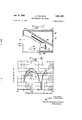
Jan. 12, 1960 L. s. HOODWIN" ELECTROACOUSTICAL DEVICE Filed Jan. 2?, 1958 2 Sheets-Sheet 2 1000 frezuejzay In Cycles Per SeeofldS Inventor Louis 5. Haodwtn ra; M'erman iBzumezlst r jttorzzez s,
United States Patent 2,921,135 ELECTROACOUSTICAL DEVICE Louis S. Hoodwin, Bridgman, Mich., assignor to Electro- Voice, Incorporated, Buchanan, Mich., a corporation of Indiana Application January 27, 1958, Serial No..7111,3.1'5
Claims. (Cl. 179-4) The present invention relatesto, electroacoustical devices, and more particularly to high fidelity sound reproducing devices.
Many high fidelity sound reproducing devices employ two or more loudspeakers because of the fact that no one set of design parameters for, a. speaker produces optimum results in the low and high frequency ranges. The sound propagation from a high frequency speaker is directional in character, however, the propagation from a low frequency speaker is nondirectional in character. As a result, a low frequency speaker placed adjacent to asound reflecting wall exhibits a frequency response characteristic measured on the axis of the speaker havinga dip in the region of 200 to 300 cycles, which results from cancellation caused by the sound reflected from the wall being out of phase with the sound emitted from the speaker, while the response characteristics of a high frequency speaker does not exhibit such a dip.
Indirect corner radiators have been used in thepast, that is, low frequency driver units which are directed into the corner of a room through an exponential horn.
. Such corner radiators employ the Walls of the room as a portion of the horn for proper loading of the driver, and the. inventor'has found that such units lose effectiveness if placed adjacent to a flat wall. Heretofore there has been no speaker enclosure for use adjacent to a sound reflecting flat wall which avoids the cancellation effects caused by sound reflected from the wall.
It is one of the objects. of this invention to provide a sound reproducing a device having a driver and enclosure which produces a relatively flat frequency response in the low frequency range and is suitable for use adjacent to a flat wall of a room, rather than a corner of a room. It is often inconvenient toplace a speaker enclosure in the corner of a room. However, the sound reproducing devices which have been employed adjacent to a flat wall heretofore have experienced undesirable dips in thev frequency response-curve produced therefrom'as a result of cancellation caused by the reflection of sound from the wall and floor of the room.
It is a further object of the present invention to provide a sound reproducing device with a driver and enclosure which may be placed adjacent to a flat wall of ,a room and which will provide a frequency response extending to higher frequencies than achieved by other enclosures with the given driver.
These and additional objects of the invention .will be morefully understood from a further reading of this disclosure, particularly when viewed in the. light of the drawings, in which:
at th loudspea and en o ure lust ted: inFiaurs ice 1 and 2, both when disposed adjacent to a wall and also in free space;
Figure 4 is a schematic diagram illustrating a loudspeaker and enclosure disposed within a room and the acoustical images produced thereby; and
Figure 5 is a schematic diagram illustrating the driver and enclosure illustrated in Figures 1 and 2 disposed in a corner of a room.
In Figure '1, a speaker enclosure 10 is shown resting upon a floor 12 of a room adjacent to a wall 14. Both the'fioor 12 and wall 14 are assumed to be effective sound reflecting surfaces for frequencies below 500 cycles per second. The enclosure 10 provided with two compartments 16 and 18. The compartment 16 is a quadrangular compartment closed on all sides except for an opening 20 which confronts the wall 14. A driver or loudspeaker 22 is secured to the compartment 16 about the opening 20 and forms an essentially air-tight seal thereto. The size of the compartment 16 is designed to provide proper damping for the loudspeaker 22.
The compartment 16 is formed by a front wall 24, a rear wall' 26 containing the opening 20, side walls 28 and 30, a top 32 and a bottom 34. The terms front and rear are here used relative to a person disposed within the room listening to the response of the loudspeaker andenclosure, hence the rear wall is adjacent to the wall 14 of the room. Four corner legs 36 support the compartment 16 above the floor 12.
rrThecornpartment 18-is provided with a partition 38 which extends diagonally thereacross. A mid-range speaker, or driver, 40 is mounted to the partition 38 and has a horn 42 directed to propagate sound in a direction opposite that of the loudspeaker 22. In other words, the horn 42 of the mid-range speaker 40 is directed toward the front of the enclosure 10, where the driver 22 isdirected toward the rear wall 26 of the enclosure 1.0; In like manner, a high frequency loudspeaker. 44 is also mounted within the compartment 18, and has a horn 46 directed to propagate sound from the front of the enclosure 10, rather than the back. The
vcompartment 118 employs the wall 32 as a bottom, and ,is provided with a top 47, side walls 48 and 50, and a power amplifier is equally divided bet-Ween the low frequency speaker 22 and the mid-range speaker 40, and the second crossover frequency being the frequency at which the output of the amplifier is divided equally between the mid-range loudspeaker 40 and the high frequency loudspeaker 44. For proper operation of the low frequency :speaker 22, it is necessary that the crossover frequency at which the output of the amplifier is equally divided between the speaker 22 and the mid-range speaker 40 be not greater than 300 cycles per second, as will be made clea v hereinafter.
Figure 4 schematically illustrates the floor and wall of a room, which may be the floor 12 and wall 14. A
, speaker enclosure, schematically illustrated at 58, rests upon the floor 12 and is spaced from the wall 14. The
speaker ,enclosure 58 is of any conventional type, and a for purposes of this discussion will be considered to be of a closed infinite baffle construction. Conventionally, the loudspeaker is mounted in the front of such an enclosure, and hence isspaced substantially from the wall 14. As indicated in Figure 4, three acoustical images are formed by operation of this speaker and enclosure, one an equal distance behind the wall 14, designated 60, a second an equal distance below the floor 12, designated 62, and a third an equal distance from the junction of the wall 14 and floor 12, designated 64. While these acoustical images do not exist in reality, the frequency response from the enclosure 53 may be calculated by vectorially adding up the sound propagation from each of the images 60, 62 and 64 with that from the speaker and enclosure 58. The low frequency response from the compartment 16, illustrated in Figures 1 and 2, oriented to position the opening 20 remote from the wall, that is,
to place the front of the enclosure adjacent to the wall 14, results in a frequency response such as indicated by the curve A of Figure 3. It is to be noted, that at a frequency of approximately 260 cycles per second, the
response measured on the axis of the loudspeaker 22 in the room experiences a sharp depression which is the result of cancellation by sound reflected from the wall 14 and floor 12. However, curve B of Figure 2 illustrates the frequency response achieved at the same location by placing the driver 22 adjacent to the wall 14, as illustrated in Figure 1. It is to be noted that the response of the loudspeaker and enclosure avoids the sharp depression and has a relatively flat response char acteristic.
The desirable response characteristic achieved by positioning the driver 22 adjacent to the wall 14, as illustrated in Figure 1, results from the fact that the acoustical images are all approximately at the same location relative to the wavelength of sound at these frequencies, that is, the acoustical images have been brought very much closer together than is possible when the loudspeaker is mounted in the front panel of the enclosure. As a result, the sound is propagated from a relatively small region and assumes an efiect approaching a point source. However, a cylindrical source is more desirable than a point source, and hence the center of the loudspeaker 22 is mounted above the surface of the floor 12 by a distance of between one foot and one and one-half feet in order to achieve this effect. The desired operation of the enclosure 10 results from the fact that low frequency sound propagation is non-directional. For this reason, the low frequency speaker 22 must be driven with electrical energy below 500 cycles per second. To achieve this, the crossover network 56, as previously stated, is provided with a crossover frequency between the low frequency speaker 22 and the mid-range speaker 40 of no greater than 300 cycles per second. Further, high frequency speakers are directional, and must be directed toward the listener. Hence, a high frequency speaker must be directed between 90 and 270 degrees from the axis of propagation of the driver 22. t
It is also to be noted that the region between the enclosure 10 and the wall 14 forms a flaring horn. While the wall 14 and the rear wall 26 of the enclosure 10 are assumed to be parallel, the volume through which the sound passes is increasing. This horn effect determines the radiation resistance of the loudspeaker 22, and permits the compartment 16 to be provided with the precise volume to achieve the desired compliance. Should the compartment 16 be placed too close to the wall 14, the radiation resistance becomes excessive, and if placed too far from the wall 14, the radiation resistance becomes too low. The inventor has found that the enclosure 10 should be spaced from the wall 14 by a distance of no less than two and one-half inches and no greater than five inches. When so disposed, the response of the combined loudspeaker 22 and compartment 16, or cavity, results in a response range approximately one octave higher than can be achieved with the same driver and other enclosures positioned adjacent to a wall.
Figure 5 illustrates the use of an enclosure of the type illustrated in Figures 1 and 2 in a corner of a room.
Here, the enclosure designated 66 rests upon a floor 68 between walls 70 and 72 of a room. A triangular shaped acoustically reflecting member is disposed in the corner between the walls 70 and 72, designated 74. The member 74 is of approximately the same height as the enclosure 66, and forms a flat sound reflecting surface. The enclosure 66 is spaced from the member 74 by a distance between two and one-half and five inches with the loudspeaker of the enclosure 66 confronting the member 74. The high frequency speakers 40 and 44, however, are directed between degrees and 225 degrees from the propagation direction of the low frequency speaker 22. Operation of the enclosure 66 is in other respects similar to that described above for the enclosure '10 positioned adjacent to a wall of the room.
From the foregoing disclosure, those skilled in the art will readily devise many modifications and applications for the present invention not specifically disclosed. It is, therefore, intended that the scope of the present invention be not limited by the foregoing disclosure, but rather only by the appended claims.
The invention claimed is:
1. A sound reproducing device comprising a structure having a horizontal floor and a vertical wall, an enclosure disposed on the floor of said structure between two and one-half and five inches from the Wall thereof having having a response below 500 cycles per second mounted in said opening, the low frequency speaker being disposed between one and one and one-half feet from the horizontal floor, and a high frequency speaker mounted to the enclosure directed in the opposite direction from the low frequency speaker.
2. A sound reproducing device for use in a room comprising a quadrangular enclosure having a base adapted to be disposed upon the fioor of the room and an opening in one side between one foot and one and one-half feet from the base and approximately midway between the other two sides of the enclosure, said enclosure being adapted to be disposed between two and one-half and five inches from a wall of the room with the opening confronting the wall, a low frequency speaker having a response below 500 cycles per second mounted in said opening, and a high frequency speaker mounted to the wall of the enclosure opposite the opening and having a horn directed away from the wall of the enclosure having the opening.
3. A sound reproducing device for use in a room comprising an enclosure having an opening therein, a low frequency speaker having a response below 500 cycles per second mounted in said opening and adapted to confront a wall of the room, means to mount a high frequency speaker to the enclosure directed in the opposite direction from the low frequency speaker, and a crossover network electrically connected to the two speakers having a cross over frequency no greater than 300 cycles per second.
4. A sound reproducing device for use in a room com- .prising an enclosure having an opening therein, a low frequency speaker having a response below 500 cycles per second mounted in said opening and adapted to confront a wall of the room, a high frequency speaker mounted to the enclosure and directed oppositely to the lon fre quency speaker, a mid-range speaker mounted to the enclosure and directed oppositely to the low frequency speaker, and a crossover network having an input and three outputs, one output being connected to each of the three speakers, said crossover network having a crossover frequency no greater than 300 cycles per second between the low frequency speaker and the mid-range speaker.
5. A sound reproducing device for use adjacent to the corner of a room comprising an enclosure having an opening therein, a low frequency speaker having a response below 500 cycles per second mounted in said 5 6 opening and adapted to confront the corner of the room, low frequency speaker and adapted to be spaced theremeans to mount a high frequency speaker to the enclofrom by a distance of two and one-half to five inches.
sure directed between 135 and 225 degrees from the propagation direction of the low frequency speaker, and References Clted the file 0f thls Patent means adapted to be disposed at the corner of the room 5 UNITED STATES PATENTS providing a flat sound reflecting surface confronting the 2,539,327 Reid et a1. Jam 23, 1951 UNITED STATES PATENT OFFICE CERTIFICATE OF CORRECTION Patent No. 2,921, 135 January 12, 1960 Louis S. Hoodwin It is hereby certified that error appears in the printed specification of the above numbered patent requiring correction and that the said Letters Patent should read as corrected below.
(SEAL) Attest:
KARL H. AXLINE ROBERT C. WATSON Attesting Oflicer Commissioner of Patents
Priority Applications (1)
| Application Number | Priority Date | Filing Date | Title |
|---|---|---|---|
| US711315A US2921135A (en) | 1958-01-27 | 1958-01-27 | Electroacoustical device |
Applications Claiming Priority (1)
| Application Number | Priority Date | Filing Date | Title |
|---|---|---|---|
| US711315A US2921135A (en) | 1958-01-27 | 1958-01-27 | Electroacoustical device |
Publications (1)
| Publication Number | Publication Date |
|---|---|
| US2921135A true US2921135A (en) | 1960-01-12 |
Family
ID=24857583
Family Applications (1)
| Application Number | Title | Priority Date | Filing Date |
|---|---|---|---|
| US711315A Expired - Lifetime US2921135A (en) | 1958-01-27 | 1958-01-27 | Electroacoustical device |
Country Status (1)
| Country | Link |
|---|---|
| US (1) | US2921135A (en) |
Cited By (5)
| Publication number | Priority date | Publication date | Assignee | Title |
|---|---|---|---|---|
| US3115548A (en) * | 1960-10-26 | 1963-12-24 | James Willis Hughes | Lecterns, pulpits, speakers' stands, and the like |
| US3166147A (en) * | 1962-05-07 | 1965-01-19 | Walter B Udell | Loudspeaker system |
| US3360072A (en) * | 1962-10-12 | 1967-12-26 | Carlsson Stig | Sound reproducing apparatus |
| US3627948A (en) * | 1969-08-18 | 1971-12-14 | Electro Voice | Stereo loudspeaker system |
| US4227050A (en) * | 1979-01-11 | 1980-10-07 | Wilson Bernard T | Virtual sound source system |
Citations (1)
| Publication number | Priority date | Publication date | Assignee | Title |
|---|---|---|---|---|
| US2539327A (en) * | 1947-07-23 | 1951-01-23 | Avco Mfg Corp | Cabinet for radio apparatus |
-
1958
- 1958-01-27 US US711315A patent/US2921135A/en not_active Expired - Lifetime
Patent Citations (1)
| Publication number | Priority date | Publication date | Assignee | Title |
|---|---|---|---|---|
| US2539327A (en) * | 1947-07-23 | 1951-01-23 | Avco Mfg Corp | Cabinet for radio apparatus |
Cited By (5)
| Publication number | Priority date | Publication date | Assignee | Title |
|---|---|---|---|---|
| US3115548A (en) * | 1960-10-26 | 1963-12-24 | James Willis Hughes | Lecterns, pulpits, speakers' stands, and the like |
| US3166147A (en) * | 1962-05-07 | 1965-01-19 | Walter B Udell | Loudspeaker system |
| US3360072A (en) * | 1962-10-12 | 1967-12-26 | Carlsson Stig | Sound reproducing apparatus |
| US3627948A (en) * | 1969-08-18 | 1971-12-14 | Electro Voice | Stereo loudspeaker system |
| US4227050A (en) * | 1979-01-11 | 1980-10-07 | Wilson Bernard T | Virtual sound source system |
Similar Documents
| Publication | Publication Date | Title |
|---|---|---|
| US4164988A (en) | Fine tuned, column speaker system | |
| US3125181A (en) | pawlowski | |
| US3983333A (en) | Loud speaker system | |
| US4270023A (en) | Cylindrical speaker mechanism | |
| US5123500A (en) | Loudspeaker enclosure | |
| US3160225A (en) | Sound reproduction system | |
| US4284844A (en) | Loudspeaker system | |
| US3582553A (en) | Loudspeaker system | |
| US3952159A (en) | Ducted port reflex enclosure | |
| US2872516A (en) | Speaker assembly | |
| US4730694A (en) | Electro-mechanical reproduction of sound | |
| US4408678A (en) | Loudspeaker enclosure | |
| US9351059B1 (en) | Orthogonal open back speaker system | |
| US3473625A (en) | Sound reproduction system and loudspeaker assembly | |
| GB765183A (en) | Improvements in or relating to loudspeakers | |
| US3882962A (en) | Loudspeaker equipment | |
| US3247926A (en) | Loud-speaker enclosure | |
| US4207963A (en) | Loudspeaker system | |
| US2896736A (en) | Acoustic system | |
| US2904123A (en) | Loud-speaker enclosures | |
| US2921135A (en) | Electroacoustical device | |
| US4753317A (en) | Trapezoidal loudspeaker enclosure | |
| US4119799A (en) | Critical alignment loudspeaker system | |
| US3523589A (en) | High-compliance speaker and enclosure combination | |
| US2835335A (en) | Loudspeaker housing using an open side as a horn mouth |