US2920522A - Musical instrument - Google Patents
Musical instrument Download PDFInfo
- Publication number
- US2920522A US2920522A US561225A US56122556A US2920522A US 2920522 A US2920522 A US 2920522A US 561225 A US561225 A US 561225A US 56122556 A US56122556 A US 56122556A US 2920522 A US2920522 A US 2920522A
- Authority
- US
- United States
- Prior art keywords
- string
- striker
- keys
- striking
- instrument
- Prior art date
- Legal status (The legal status is an assumption and is not a legal conclusion. Google has not performed a legal analysis and makes no representation as to the accuracy of the status listed.)
- Expired - Lifetime
Links
Images


Classifications
-
- G—PHYSICS
- G10—MUSICAL INSTRUMENTS; ACOUSTICS
- G10C—PIANOS, HARPSICHORDS, SPINETS OR SIMILAR STRINGED MUSICAL INSTRUMENTS WITH ONE OR MORE KEYBOARDS
- G10C3/00—Details or accessories
- G10C3/10—Tuning pins; Tensioning devices
Definitions
- This invention comprises a musical instrument involving certain fundamental features wherein an object of the invention is to provide such an instrument in which a single string operates in conjunction with an electric pick up device adapted to be connected to an amplifier to produce the notes of several octaves of the musical scale by said single string using a striking mechanism,.
- my invention eliminates the need of a sounding board or box.
- Another object of this invention resides in the particular construction of the striking element itself, its connection with the keys as well as the mounting of the striking mechanisms according to the chromatic scale whereby the player of the instrument may readily operate the same as in the ordinary case of a piano keyboard.
- this instrument may be provided with means to produce a vibrato effect.
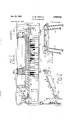
- Figure I is a top plan view of-one embodiment of my invention with certain parts thereof broken away;
- Figure II is a perspective view of the complete instrument, at a reduced scale
- Figure III is an enlarged section taken on the line III-III of Figure I; v
- Figure IV is a partial plan view of the striking mechanism
- Figure V is a perspective elevation of one of the striking elements
- Figure V1 is a section taken on the line VI-VI of Figure III;
- Figure VII is an enlarged section taken on the line VIIIVIII of Figure III;
- Figure VIII is an enlarged sectional on the line VIII-VIII of Figure I;
- Figure IX is an enlarged plan view of one end of the instrument showing the vibrato mechanism
- bracket members 14 and 15 Adjacent each end of the base board 11, I provide upright supporting bracket members 14 and 15 adapted to rigidly carry a longitudinal tensioning or stretch bar 16 above which is stretched a single steel string or wire 18, the same being secured taut to said brackets 14 and 15 above said bar 16 by suitable adjusting and tensioning means as in guitars and pianos and hereinafter more fully described.
- a standard type of keyboard 20 having the usual pivoted keys 21 and base 22 is fixed on the frame board 11.
- the keys 21 extend from the front of the instrument to the rear thereof and I here show three octaves of individual keys. These keys pass beneath the 'bar 16 and string 18 while the striker arms 25 are pivotally hung as hereinafter described from another longitudinal supporting bar 26, said striker arms extending crosswise of the instrument from the back side Where they are connected to the keys toward the front side to a position above the string 18 where a striker hammer 28 connected to each striker arm 25 is in position to strike the wire 18 and simultaneously form a fret therefor.
- the electromagnetic pick up 30 is carried by the one of the righthand bracket member14 so that the field of said electromagnet is in the path of vibration of the metallic wire 18 when the latter is vibrated.
- Adjacent the other, end of said string 18 and carried by said stretch bar 16 is a damping device 31 preferably including a pair of sponge rubber blocks arranged to surround the wire 18 as shown in Figure XI, being held in contact therewith so that the damping means 31 practically receives the wire 18 embedded therein.
- a clip 32 forms a convenient means for holding the sponge rubber pads 31 to the bar 16 and this damping means may be adjusted longitudinally of the string or wire 18.
- An important feature of the present invention includes in the particular angularity of the striker arms 25 compared with thenormal position for each of the several keys 21 illustrated in Figure I.
- I use a standard keyboard 20 with the keys 21, whereas the striking hammer 28 string 18 according to the chromatic scale so that with the--singlestring 18 Iain able'to play three octaves of i
- This-bar 26- is-provided with an extending center slot.
- each saddle 37 is lined with felt and has an upwardly extending screw threaded pin'38 which is adapted to pass through the slot 36 in the supporting bar 26.
- suitable nuts 39 each of the saddles 37 can be anchored at any required particular position.
- these saddles 37 are properly spaced longitudinally along the supporting bar- 26'whereby the striking arms or elements are spaced along string 18 according to the chromatic scale so that when the keys are depressed, the striking hammers 28will actually contact the string 18 at exactly the correct point to give the correct note.
- pivotal member 42 of the striking arm 25 The specific manner in which I have connected the pivotal member 42 of the striking arm 25 is shown in Figure V where it will be seen that this pivot 42 includes the cutaway cylindrical member 44 so that the same may be slid back and forth on the rear end of the arm 25.
- the member 44 has at the lower end a downwardly extending small portion or pin 45 adapted to extend into the barrel 40.
- the entire pivotal element may be slid along on the rear portion of the striker arm 25'-and set in any particular position required by set screw 46 which passes down through the center of'the 50 and carrying a plurality of small leather washers 53 between said head and the lower, end of the barrel 40.
- I also provide a rounded circumferential edge to the bottom of the barrel 40 as shown at 55.
- Atthe upper end of the barrel 40 I also provided a similar curved or rounded end to the circumferential periphery andv also employ some washers 56 and 57 between the lower end of the pivotalmember 42 and the top of the barrel 40
- each of these individual springs 60 may be anchored thereto. Moreoven as I desire. to slide these springs, 60 longitudinally on the wire 61, it will be noted that 1 connect the coil spring 60 to thewire by means of a loop in the end of the spring.
- the upper end of the spring 68 is connected by an elongated hooked rod 62 having a screw threaded upper end 63 which may be connected to the upper pivoted mechanism 42- by means of a traversely extended arm 64 having an opening therethrough for receiving the upper screw threaded end 63 of the rod 62 and by use of'a small nut 65, the tension of the spring 60 may be adjusted.
- the transverse small plate 64 is connected to the upper end 44 of the pivotal element 42 by use of the screw 46 which also forms the means for adjusting the pivotal member 42 as stated supra, since I provide a nut 66 for this purpose.
- thispulley is provided with a central bore 85 off-center as indicated in Figure IX' by the amount ofeccentricity desired.
- the eccentrically mounted pulley is driven by a small belt 87 connected witha wheel 88 on a small electric motor 89 suitably mounted in fixed position in the bottom of the framework 'of the instrument.
- the wheel 88 drives the eccentric pulley 80 through the belt 87 and this in turn will swing the rod 75; abovefthev pivot point 78 through the medium of the bracket 81.
- I The result of this will be a slight extensiontand retraction of the string or wire 18 which causes the vibrato effect.
- the amplifier referred to hereinrnay be of the type such. as shown. inPatent 2,725,778 of" December 6, 1955, to. Cronwell.
- a musical instrument with a vibratory single metal string; a frame; spaced supports on said frame between which said string is stretched; electro-magnetic pick up means carried by said frame adjacent one of said supports; an amplifier adapted to be actuated by said pick up; a plurality of operable keys pivotly carried by said frame and extending from the front to the rear of said instrument; a plurality of strikers pivotly suspended by said frame adapted to be in position to contact said string at spaced intervals according to the chromatic scale; a connecting linkage between the rear end of said keys and the rear end of said strikers whereby upon depression of a key, the strikers will contact and vibrate said string and damping means for contacting said string adjacent the other of said supports, said connecting linkage between a key and a striker including an upwardly extending pin fixed adjacent the rear of said key; a tube freely carried by said pin and a pin connected to said strikers and extending into the other end of said tube.
- An electro mechanical musical instrument comprising a single steel string and two solid non-resonant supports; means to stretch said string between said supports; a plurality of octaves of keys positioned along said string; a plurality of combined fret forming and string striker elements positioned for operative connection to said keys and spaced to form various lengths according to a chr0- matic scale for said string from one of said supports to the point of contact of a striker element and said string; said striker elements having an inclined face arranged so that each striker contacts the metal string at substantially right angle thereto an electro-magnetic pick up positioned adjacent said string between the point of one of said striker elements engaging said string for forming the highest note and one of said string supports; and a damping means for said string adjacent the other of said supports between said support and the lowest note produced.
- a musical instrument including a metallic vibratory string and a suitable solid non-resonant support; said vibratory string secured taut to said support a plurality of manually operable keys transversely arranged with respect to said string, each key having a string striking element for said string located adjacent and above said string, said keys spaced from said string and located adjacent each other longitudinally with respect to said string with said striking elements spaced one from another longitudinally of said string according to a musical chromatic scale, each of said keys being pivotally mounted on said support, whereby when the key is depressed said striker is moved through an arc around said pivot, the striking element of said keys having a string contacting surface beveled at an angle when in inoperative position so as to strike said string substantially at right angles when the key is depressed by the operator; and an electromagnetic pick up located adjacent one end of said string and at that end of said string upon which said striking elements contact the same according to said chromatic scale.
- a musical instrument including a metallic vibratory string and a suitable support said vibratory string secured taut to said support; a plurality of manually operable keys transversely arranged with respect to said string; pivoted striking arms each having a striking element one for each correct note to be produced by said string, said striking arms and striking elements located adjacent and above said string, said keys spaced from said string and located adjacent each other longitudinally of said string according to a musical chromatic scale, each of said keys being pivotally mounted below said string and extending horizontally and rearwardly thereof, links on said support for adjustably connecting said keys to said striking elements, whereby when the key is depressed said striker is moved through an are around said pivot, the striking element of said keys having a string contacting surface beveled at an angle when in inoperative position so as to strike said string substantially at right angles when the key is depressed by the operator; an electro-magnetic pick up located adjacent one end of said string; and a damping means for said string adjacent the other of said supports between said support and the lowest note produced.
- An electro-mechanical musical instrument comprising a single steel string and two solid non-resonant supports; means to stretch said string between said supports; a plurality of octaves of keys positioned along said string; a plurality of combined fret forming and string striker elements positioned for operative connection to said keys and spaced to form various lengths according to a chromatic scale for said string from one of said supports to the point of contact of a striker element and said string, said striker elements having an inclined face arranged so that each striker contacts the metal string at substantially right angles thereto and the transverse face of said inclined surface being curved convexly with respect to said string; an electro-magnetic pick up positioned adjacent said string between the point of forming the highest note and one of said string supports; and a damping means for said string adjacent the other of said supports between said support and the lowest note produced.
Landscapes
- Physics & Mathematics (AREA)
- Engineering & Computer Science (AREA)
- Acoustics & Sound (AREA)
- Multimedia (AREA)
- Stringed Musical Instruments (AREA)
- Electrophonic Musical Instruments (AREA)
Description
Jan. 12, 1960 H. DE ARMOND MUSICAL INSTRUMENT Filed Jan. 25, 1956 ELECTRON lC PICK UP 3 Sheets-Sheet 1 I I 3 N INV TOR. Harry De Armand H. DE ARMOND MUSICAL INSTRUMENT Jan. 12, 1960 Filed Jan. 25, 1956 3 Sheets-Sheet 2 8 00 INVENTOR N BY Harry 0e rmam/ ATTaR/VEY Jan. 12, 1960 5 ARMOND I 2,920,522
MUSICAL INSTRUMENT Filed Jan. 25, 1956 3 Sheets-Sheet 3 I :W [WI SPONGE RUBBER 76 INVEN TOR.
Harry 0:? Armand BY i g United States Patent MUSICAL INSTRUMENT Harry De Armond, Toledo, Ohio Application January 25, 1956, Serial No. 561,225
5 Claims. c1. 84-1.16)
This invention comprises a musical instrument involving certain fundamental features wherein an object of the invention is to provide such an instrument in which a single string operates in conjunction with an electric pick up device adapted to be connected to an amplifier to produce the notes of several octaves of the musical scale by said single string using a striking mechanism,.
the striking element of which causes both the vibration of the string for producing the musical notes picked up and determines the length of the string so vibrated and consequently the pitch of the note. Moreover, my invention eliminates the need of a sounding board or box.
Further objects of this invention include the means whereby one string is properly divided to produce the various notes as indicated and the special mechanism for striking the same, the arrangement forming a combined striker and fret forming device.
Another object of this invention resides in the particular construction of the striking element itself, its connection with the keys as well as the mounting of the striking mechanisms according to the chromatic scale whereby the player of the instrument may readily operate the same as in the ordinary case of a piano keyboard.
It is a still further object of the present invention to provide a special surface of the striker compared with its arc of movement to obtain a clear, sharp contact to properly vibrate the string and avoid a rubbing or sliding effect in contacting the string by the striker. I
Moreover, this instrument may be provided with means to produce a vibrato effect.
Further objects and advantages are within the scope of this invention, such as relate to the arrangement, operation and function of the related elements of the structure, to various details of construction and to combinations of parts, elements per se, and to economics of manufacture and numerous other features, as will be apparent from a consideration of the specification and drawing of a form of the invention, which may be preferred, in which:
Figure I is a top plan view of-one embodiment of my invention with certain parts thereof broken away;
Figure II is a perspective view of the complete instrument, at a reduced scale;
Figure III is an enlarged section taken on the line III-III of Figure I; v
Figure IV is a partial plan view of the striking mechanism;
Figure V is a perspective elevation of one of the striking elements; I
Figure V1 is a section taken on the line VI-VI of Figure III;
Figure VII is an enlarged section taken on the line VIIIVIII of Figure III;
Figure VIII is an enlarged sectional on the line VIII-VIII of Figure I;
Figure IX is an enlarged plan view of one end of the instrument showing the vibrato mechanism;
elevation taken 2,920,522 Patented Jan. 12, 1960 '12 which may be detachable to facilitate carrying the instrument.
Adjacent each end of the base board 11, I provide upright supporting bracket members 14 and 15 adapted to rigidly carry a longitudinal tensioning or stretch bar 16 above which is stretched a single steel string or wire 18, the same being secured taut to said brackets 14 and 15 above said bar 16 by suitable adjusting and tensioning means as in guitars and pianos and hereinafter more fully described.
A standard type of keyboard 20 having the usual pivoted keys 21 and base 22 is fixed on the frame board 11. As clearly shown in the drawings the keys 21 extend from the front of the instrument to the rear thereof and I here show three octaves of individual keys. These keys pass beneath the 'bar 16 and string 18 while the striker arms 25 are pivotally hung as hereinafter described from another longitudinal supporting bar 26, said striker arms extending crosswise of the instrument from the back side Where they are connected to the keys toward the front side to a position above the string 18 where a striker hammer 28 connected to each striker arm 25 is in position to strike the wire 18 and simultaneously form a fret therefor.
Adjacent the right side of the support, as indicated in Figure I, is an electric pick up device 30 adapted to be connected to a suitable amplifier not shown. The electromagnetic pick up 30 is carried by the one of the righthand bracket member14 so that the field of said electromagnet is in the path of vibration of the metallic wire 18 when the latter is vibrated. Adjacent the other, end of said string 18 and carried by said stretch bar 16 is a damping device 31 preferably including a pair of sponge rubber blocks arranged to surround the wire 18 as shown in Figure XI, being held in contact therewith so that the damping means 31 practically receives the wire 18 embedded therein. A clip 32 forms a convenient means for holding the sponge rubber pads 31 to the bar 16 and this damping means may be adjusted longitudinally of the string or wire 18. In the present invention, as stated supra, I thus provide by the means described a combined fret and striking element whereby the correct musical notes may be reproduced from the vibration of said wire 18 through said pick up 30 and suitably amplified. As shown in Figure VI, it will be noted that I provide a certain curved transverse configuration to the face 33 of the striker hammer element 28 so that when the front end of the key 21 is depressed this surface 33 will actually contact the string 18 so as to make a sharp clear impact with the string rather than with a sliding or rolling contact therewith. As shown in Figure III, this face 33 is also inclined downwardly toward the front end of the hammer28 instead of being horizontal. When the striker arm 25 swings around its pivot 34 the surface 33 will therefore come into a right angle contact with string 18.
An important feature of the present invention includes in the particular angularity of the striker arms 25 compared with thenormal position for each of the several keys 21 illustrated in Figure I. I use a standard keyboard 20 with the keys 21, whereas the striking hammer 28 string 18 according to the chromatic scale so that with the--singlestring 18 Iain able'to play three octaves of i This-bar 26- is-provided with an extending center slot.
36- as indicated in Figure IV' and the individual striker arms 2'5 are supported from said bar 26. by adjustable inverted U-shaped saddle members 37 to which are pivoted as at 34 the striker arms 25. Each saddle 37 is lined with felt and has an upwardly extending screw threaded pin'38 which is adapted to pass through the slot 36 in the supporting bar 26. By suitable nuts 39 each of the saddles 37 can be anchored at any required particular position. As stated supra, these saddles 37 are properly spaced longitudinally along the supporting bar- 26'whereby the striking arms or elements are spaced along string 18 according to the chromatic scale so that when the keys are depressed, the striking hammers 28will actually contact the string 18 at exactly the correct point to give the correct note.
The manner in which thestriker arms 25, on the one hand are individually connected with keys 21 on theother hand is also illustrated in Figure III and in this particular embodiment of my invention I provide a loose pivotal connection between these two elements which are arranged so that the striker arm 25 may be swung at any particular angle necessary whereas the keys 21--using a standard keyboard-are located at substantially right angles to the string 18. One satisfactory connection between arms 25 and keys 21 of this type includes a vertically positioned tube or barrel 40, preferably of wood, which isconnected'to the rear end of an individual key 21' by an upwardly extended pivotal bearing unit 41, whereas at the upper end, the rear end of each of the striker arms 25 also is provided with a pivotal connection between the striker arm 25, and said barrel 40 as indicated at 42. The specific manner in which I have connected the pivotal member 42 of the striking arm 25 is shown in Figure V where it will be seen that this pivot 42 includes the cutaway cylindrical member 44 so that the same may be slid back and forth on the rear end of the arm 25. The member 44 has at the lower end a downwardly extending small portion or pin 45 adapted to extend into the barrel 40. The entire pivotal element may be slid along on the rear portion of the striker arm 25'-and set in any particular position required by set screw 46 which passes down through the center of'the 50 and carrying a plurality of small leather washers 53 between said head and the lower, end of the barrel 40. I also provide a rounded circumferential edge to the bottom of the barrel 40 as shown at 55. Atthe upper end of the barrel 40, I also provided a similar curved or rounded end to the circumferential periphery andv also employ some washers 56 and 57 between the lower end of the pivotalmember 42 and the top of the barrel 40.
I also provide spring means to return the keys, and,
striker mechanism immediately to normal position after akey has been struck. To this end I provide as shown in Figure III a spring 60 for each key and striker'connection and a longitudinal wire 61 extending entirely the th o h nstr ment m on t h o h r so.
Y 4 that each of these individual springs 60 may be anchored thereto. Moreoven as I desire. to slide these springs, 60 longitudinally on the wire 61, it will be noted that 1 connect the coil spring 60 to thewire by means of a loop in the end of the spring. The upper end of the spring 68 is connected by an elongated hooked rod 62 having a screw threaded upper end 63 which may be connected to the upper pivoted mechanism 42- by means of a traversely extended arm 64 having an opening therethrough for receiving the upper screw threaded end 63 of the rod 62 and by use of'a small nut 65, the tension of the spring 60 may be adjusted. It is noted that the transverse small plate 64 is connected to the upper end 44 of the pivotal element 42 by use of the screw 46 which also forms the means for adjusting the pivotal member 42 as stated supra, since I provide a nut 66 for this purpose.
In order to properly tension the string or wire 18, I employ a standard type of tuning device 70 shown in Figure I. The other end of the string or wire 18 is conbeing positioned between said bracket and the pivotal rod by-being fixed thereto, by any suitable means. The spring is arranged so that it is always under compression, both thestring 18 and the spring 77 being on the same side of the pivot point78 of the rod 75, whereby the spring 77 overcomes the pull of the string 18, balancing the pivotal rod 75.
Thus, I obtain avibrato effect by slightly lengthening and-shortening the string 18 and to this end the end of the pivot rod75 is connected with an eccentric pulley 80. One satisfactory. arrangement for effecting this vibrato consists of a plate 81 extending underneath the rod 75, the rod 75 being flattened where it is attached, as indicated at 82 to the plate 81, so that the plate may be adjusted longitudinally of the rod 75, the plate 81 carryinga fixed pivot 84 extending upwardly from the plate asshown in Figure X. To form the eccentric'mounting for the pulley 80, thispulley is provided with a central bore 85 off-center as indicated in Figure IX' by the amount ofeccentricity desired, The eccentrically mounted pulley is driven by a small belt 87 connected witha wheel 88 on a small electric motor 89 suitably mounted in fixed position in the bottom of the framework 'of the instrument. As the electric motor 89 is driven, the wheel 88 drives the eccentric pulley 80 through the belt 87 and this in turn will swing the rod 75; abovefthev pivot point 78 through the medium of the bracket 81. I The result of this will be a slight extensiontand retraction of the string or wire 18 which causes the vibrato effect.
The amplifier referred to hereinrnay be of the type such. as shown. inPatent 2,725,778 of" December 6, 1955, to. Cronwell.
From the foregoing, the operation of the instrument will: be understood, an. ordinary piano keyboard being used in my invention and the depression of the keys as shown will cause the notes'to be reproduced on the loud speaker, since the combinedstriker and. fret forming" hammers 28 are positioned according to a chromatic scale for the part of the wire which includes the pick up device 30. while the dampers 31. at the other end mute out any vibrations of that portion of the wire. As-lon-g as the motor 89' operates, a vibrato effect is produced and if it is desired to play the instrument without the vibrato effect, a suitable switch in the electric motor circuit may be opened.
It is; apparent that within the scope of the invention, modifications and" different arrangements may be madeother than herein disclosed, and the present disclosure is illustrative merely, the invention comprehending all variations thereof.
What I claim is:
1. In a musical instrument, with a vibratory single metal string; a frame; spaced supports on said frame between which said string is stretched; electro-magnetic pick up means carried by said frame adjacent one of said supports; an amplifier adapted to be actuated by said pick up; a plurality of operable keys pivotly carried by said frame and extending from the front to the rear of said instrument; a plurality of strikers pivotly suspended by said frame adapted to be in position to contact said string at spaced intervals according to the chromatic scale; a connecting linkage between the rear end of said keys and the rear end of said strikers whereby upon depression of a key, the strikers will contact and vibrate said string and damping means for contacting said string adjacent the other of said supports, said connecting linkage between a key and a striker including an upwardly extending pin fixed adjacent the rear of said key; a tube freely carried by said pin and a pin connected to said strikers and extending into the other end of said tube.
2. An electro mechanical musical instrument comprising a single steel string and two solid non-resonant supports; means to stretch said string between said supports; a plurality of octaves of keys positioned along said string; a plurality of combined fret forming and string striker elements positioned for operative connection to said keys and spaced to form various lengths according to a chr0- matic scale for said string from one of said supports to the point of contact of a striker element and said string; said striker elements having an inclined face arranged so that each striker contacts the metal string at substantially right angle thereto an electro-magnetic pick up positioned adjacent said string between the point of one of said striker elements engaging said string for forming the highest note and one of said string supports; and a damping means for said string adjacent the other of said supports between said support and the lowest note produced.
3. A musical instrument including a metallic vibratory string and a suitable solid non-resonant support; said vibratory string secured taut to said support a plurality of manually operable keys transversely arranged with respect to said string, each key having a string striking element for said string located adjacent and above said string, said keys spaced from said string and located adjacent each other longitudinally with respect to said string with said striking elements spaced one from another longitudinally of said string according to a musical chromatic scale, each of said keys being pivotally mounted on said support, whereby when the key is depressed said striker is moved through an arc around said pivot, the striking element of said keys having a string contacting surface beveled at an angle when in inoperative position so as to strike said string substantially at right angles when the key is depressed by the operator; and an electromagnetic pick up located adjacent one end of said string and at that end of said string upon which said striking elements contact the same according to said chromatic scale.
4. A musical instrument including a metallic vibratory string and a suitable support said vibratory string secured taut to said support; a plurality of manually operable keys transversely arranged with respect to said string; pivoted striking arms each having a striking element one for each correct note to be produced by said string, said striking arms and striking elements located adjacent and above said string, said keys spaced from said string and located adjacent each other longitudinally of said string according to a musical chromatic scale, each of said keys being pivotally mounted below said string and extending horizontally and rearwardly thereof, links on said support for adjustably connecting said keys to said striking elements, whereby when the key is depressed said striker is moved through an are around said pivot, the striking element of said keys having a string contacting surface beveled at an angle when in inoperative position so as to strike said string substantially at right angles when the key is depressed by the operator; an electro-magnetic pick up located adjacent one end of said string; and a damping means for said string adjacent the other of said supports between said support and the lowest note produced.
5. An electro-mechanical musical instrument comprising a single steel string and two solid non-resonant supports; means to stretch said string between said supports; a plurality of octaves of keys positioned along said string; a plurality of combined fret forming and string striker elements positioned for operative connection to said keys and spaced to form various lengths according to a chromatic scale for said string from one of said supports to the point of contact of a striker element and said string, said striker elements having an inclined face arranged so that each striker contacts the metal string at substantially right angles thereto and the transverse face of said inclined surface being curved convexly with respect to said string; an electro-magnetic pick up positioned adjacent said string between the point of forming the highest note and one of said string supports; and a damping means for said string adjacent the other of said supports between said support and the lowest note produced.
References Cited in the file of this patent UNITED STATES PATENTS 666,138 Halle Jan. 15, 1901 1,579,791 Sandell Apr. 6, 1926 1,750,572 Cloetens Mar. 11, 1930 2,175,325 Sunshine Oct. 10, 1939 2,486,647 Harker Nov. 1, 1949 2,494,485 Notara Jan. 10, 1950 2,725,778 Cronwell Dec. 6, 1955 FOREIGN PATENTS 339,690 Great Britain Dec. 18, 1930
Priority Applications (1)
| Application Number | Priority Date | Filing Date | Title |
|---|---|---|---|
| US561225A US2920522A (en) | 1956-01-25 | 1956-01-25 | Musical instrument |
Applications Claiming Priority (1)
| Application Number | Priority Date | Filing Date | Title |
|---|---|---|---|
| US561225A US2920522A (en) | 1956-01-25 | 1956-01-25 | Musical instrument |
Publications (1)
| Publication Number | Publication Date |
|---|---|
| US2920522A true US2920522A (en) | 1960-01-12 |
Family
ID=24241132
Family Applications (1)
| Application Number | Title | Priority Date | Filing Date |
|---|---|---|---|
| US561225A Expired - Lifetime US2920522A (en) | 1956-01-25 | 1956-01-25 | Musical instrument |
Country Status (1)
| Country | Link |
|---|---|
| US (1) | US2920522A (en) |
Cited By (3)
| Publication number | Priority date | Publication date | Assignee | Title |
|---|---|---|---|---|
| US3474180A (en) * | 1968-12-23 | 1969-10-21 | American Express | Electronic stringed musical instrument of percussion |
| US4236433A (en) * | 1979-04-02 | 1980-12-02 | Stephen Holland | Electric string instrument |
| USD405294S (en) | 1994-11-03 | 1999-02-09 | Andre Ansfried Jozef Adams | Support for xylophone/marimba |
Citations (8)
| Publication number | Priority date | Publication date | Assignee | Title |
|---|---|---|---|---|
| US666138A (en) * | 1900-08-14 | 1901-01-15 | Clifford Robert Stephen John Halle | Pianoforte. |
| US1579791A (en) * | 1922-07-15 | 1926-04-06 | Mills Novelty Co | Tremold device for self-playing stringed instruments |
| US1750572A (en) * | 1927-04-30 | 1930-03-11 | Cloetens Georges | Musical instrument |
| GB339690A (en) * | 1929-03-25 | 1930-12-18 | Edouard Magat | |
| US2175325A (en) * | 1937-11-10 | 1939-10-10 | Epiphone Inc | Magnetoelectric pick-up device for stringed musical instruments |
| US2486647A (en) * | 1946-02-08 | 1949-11-01 | Harker William Ernest | Combination electrical pickup and bridge for guitars and other instruments |
| US2494485A (en) * | 1947-09-30 | 1950-01-10 | Notara Andrew Love | Musical instrument |
| US2725778A (en) * | 1952-06-13 | 1955-12-06 | Cronwell John | Sound pick-up device for the amplification of banjo music |
-
1956
- 1956-01-25 US US561225A patent/US2920522A/en not_active Expired - Lifetime
Patent Citations (8)
| Publication number | Priority date | Publication date | Assignee | Title |
|---|---|---|---|---|
| US666138A (en) * | 1900-08-14 | 1901-01-15 | Clifford Robert Stephen John Halle | Pianoforte. |
| US1579791A (en) * | 1922-07-15 | 1926-04-06 | Mills Novelty Co | Tremold device for self-playing stringed instruments |
| US1750572A (en) * | 1927-04-30 | 1930-03-11 | Cloetens Georges | Musical instrument |
| GB339690A (en) * | 1929-03-25 | 1930-12-18 | Edouard Magat | |
| US2175325A (en) * | 1937-11-10 | 1939-10-10 | Epiphone Inc | Magnetoelectric pick-up device for stringed musical instruments |
| US2486647A (en) * | 1946-02-08 | 1949-11-01 | Harker William Ernest | Combination electrical pickup and bridge for guitars and other instruments |
| US2494485A (en) * | 1947-09-30 | 1950-01-10 | Notara Andrew Love | Musical instrument |
| US2725778A (en) * | 1952-06-13 | 1955-12-06 | Cronwell John | Sound pick-up device for the amplification of banjo music |
Cited By (3)
| Publication number | Priority date | Publication date | Assignee | Title |
|---|---|---|---|---|
| US3474180A (en) * | 1968-12-23 | 1969-10-21 | American Express | Electronic stringed musical instrument of percussion |
| US4236433A (en) * | 1979-04-02 | 1980-12-02 | Stephen Holland | Electric string instrument |
| USD405294S (en) | 1994-11-03 | 1999-02-09 | Andre Ansfried Jozef Adams | Support for xylophone/marimba |
Similar Documents
| Publication | Publication Date | Title |
|---|---|---|
| US6740800B1 (en) | Portable keyboard tremolo musical instrument | |
| US3680423A (en) | Combined drum-guitar musical instrument | |
| US3049958A (en) | Electro-piano | |
| US4161129A (en) | Modified piano striking mechanism | |
| US4058044A (en) | Electrical musical instrument | |
| US2275252A (en) | Electrical musical instrument fob | |
| US2920522A (en) | Musical instrument | |
| US4324164A (en) | Tone changing means for percussion instruments | |
| US4149444A (en) | Rhythm instrument | |
| US2156711A (en) | Musical instrument | |
| US3255657A (en) | Piano frame and bridge bar therefor | |
| US3757026A (en) | Piano striking mechanism | |
| US2845829A (en) | Key action for musical instrument | |
| US367955A (en) | braun | |
| US1750572A (en) | Musical instrument | |
| US12148405B2 (en) | Electromagnetic multi-function multi-purpose chordophone | |
| US3306151A (en) | Musical instruments having struck vibrating members | |
| US3197542A (en) | Foot pedal string bass | |
| US382028A (en) | caldera | |
| US3443470A (en) | Musical instruments with strings parallel to keyboard and operated by the feet | |
| US3524008A (en) | Reed-type musical instrument with electromagnetic pickups | |
| US5103707A (en) | Manufacturing and tuning a musical instrument | |
| US2261345A (en) | Electrical musical instrument for producing bell tones | |
| US688893A (en) | Soundboard of stringed musical instruments. | |
| US309138A (en) | M fischeb |