US2916005A - Combined rudder and reverse control for marine craft - Google Patents
Combined rudder and reverse control for marine craft Download PDFInfo
- Publication number
- US2916005A US2916005A US577091A US57709156A US2916005A US 2916005 A US2916005 A US 2916005A US 577091 A US577091 A US 577091A US 57709156 A US57709156 A US 57709156A US 2916005 A US2916005 A US 2916005A
- Authority
- US
- United States
- Prior art keywords
- craft
- clam shell
- piston
- rudder
- propeller
- Prior art date
- Legal status (The legal status is an assumption and is not a legal conclusion. Google has not performed a legal analysis and makes no representation as to the accuracy of the status listed.)
- Expired - Lifetime
Links
- 230000002441 reversible effect Effects 0.000 title description 24
- 230000033001 locomotion Effects 0.000 description 29
- 239000007788 liquid Substances 0.000 description 15
- 230000007246 mechanism Effects 0.000 description 13
- 230000007935 neutral effect Effects 0.000 description 13
- 230000000712 assembly Effects 0.000 description 7
- 238000000429 assembly Methods 0.000 description 7
- 230000000694 effects Effects 0.000 description 3
- XLYOFNOQVPJJNP-UHFFFAOYSA-N water Substances O XLYOFNOQVPJJNP-UHFFFAOYSA-N 0.000 description 3
- 238000007789 sealing Methods 0.000 description 2
- 241000380131 Ammophila arenaria Species 0.000 description 1
- 101100497221 Bacillus thuringiensis subsp. alesti cry1Ae gene Proteins 0.000 description 1
- 229910001369 Brass Inorganic materials 0.000 description 1
- 101100489581 Caenorhabditis elegans par-5 gene Proteins 0.000 description 1
- 101100379079 Emericella variicolor andA gene Proteins 0.000 description 1
- XEEYBQQBJWHFJM-UHFFFAOYSA-N Iron Chemical group [Fe] XEEYBQQBJWHFJM-UHFFFAOYSA-N 0.000 description 1
- 101150013124 Plce1 gene Proteins 0.000 description 1
- 239000010951 brass Substances 0.000 description 1
- 238000010276 construction Methods 0.000 description 1
- 230000026058 directional locomotion Effects 0.000 description 1
- 238000009434 installation Methods 0.000 description 1
- 239000000463 material Substances 0.000 description 1
- 230000002093 peripheral effect Effects 0.000 description 1
- 230000000717 retained effect Effects 0.000 description 1
- 230000000630 rising effect Effects 0.000 description 1
- 239000011435 rock Substances 0.000 description 1
- 239000007858 starting material Substances 0.000 description 1
- 210000003813 thumb Anatomy 0.000 description 1
- 230000000007 visual effect Effects 0.000 description 1
Images


Classifications
-
- B—PERFORMING OPERATIONS; TRANSPORTING
- B63—SHIPS OR OTHER WATERBORNE VESSELS; RELATED EQUIPMENT
- B63H—MARINE PROPULSION OR STEERING
- B63H25/00—Steering; Slowing-down otherwise than by use of propulsive elements; Dynamic anchoring, i.e. positioning vessels by means of main or auxiliary propulsive elements
- B63H25/48—Steering or slowing-down by deflection of propeller slipstream otherwise than by rudder
-
- B—PERFORMING OPERATIONS; TRANSPORTING
- B63—SHIPS OR OTHER WATERBORNE VESSELS; RELATED EQUIPMENT
- B63H—MARINE PROPULSION OR STEERING
- B63H25/00—Steering; Slowing-down otherwise than by use of propulsive elements; Dynamic anchoring, i.e. positioning vessels by means of main or auxiliary propulsive elements
- B63H25/06—Steering by rudders
- B63H25/38—Rudders
- B63H25/382—Rudders movable otherwise than for steering purposes; Changing geometry
- B63H25/383—Rudders movable otherwise than for steering purposes; Changing geometry with deflecting means able to reverse the water stream direction
Definitions
- This invention relates to the steering and direction control of power operated marine craft and an object is to produce a combined rudder and direction control device which can be operated not only to control the steering but also the forward, and reverse movement of the craft as well as the neutral position thereof without altering the propeller drive.
- Another object is to produce mechanism of the above character which can be actuated and controlled at a remote station enabling the helmsman, for example, to steer and control the forward, and reverse craft movement as well as the neutral position thereof by the simple manipulation of an operating device.
- a further object is to produce a simple and efficient hydraulic mechanism for effecting actuation of the rudder parts to place the craft in forward or rearward running position or in neutral position without varying the pitch or operation of the propeller.
- a still further object is to produce an assembly embodying the rudder and reverse control mechanism, which can be readily and conveniently installed on the boat in position of use.
- a still further object is to improve rudder structures of the clam shell type to enhance the operation thereof, particularly in the position for causing reverse or rearward movement of the craft.
- a still further object is to produce a system of the above character which insures that upon the starting of the engine, the rudder components are in neutral position regardless of their position at the time the engine was stopped.
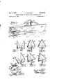
- Figure 1 is a side elevation of an inboard motor boat equipped with a combined rudder and direction control device and indicating the operating mechanism for same;
- Figure 2 is a sectional view through the propeller drive shaft showing the propeller and the clam shell type rudder and direction control device;
- Figure 3 is a top plan View of a portion of the operating mechanism for actuating the clam shell members to effect steering of the craft and also for controlling the direction of movement of the craft;
- Figure 4 is a side elevation of the mechanism shown in Figure 3, some parts in section and also showing the relation of the propeller and associated parts;
- Figure 5 is a fragmentary vertical sectional elevation on the line 5-5 of Figure 4;
- Figure 6 is an enlarged sectional View of the parts which are actuated for eecting opening and closing movements to the clam shell members;
- Figures 7 to 12 are somewhat diagrammatic sectional views showing the various positions of the combined rudder and direction control device
- Figure 13 is a diagrammatic View of the electrical wir- 2,916,005 Patented Dec. 8, 1959 plCe ing and operating units for eiecting the actuation of the rudder-direction control parts;
- Figure 14 is an enlarged longitudinal sectional View of the solenoid operated valve disposed in each of the tubes leading from the motor-pump unit to the operating cylinder;
- Figure 15 is a sectional view taken through the supporting post for the circuit position selector and viewing the latter in elevation;
- Figure 16 is a verical sectional View of the circuit selector on the line 16-16 of Figure 15;
- Figure 17 is a vertical sectional View on the line 17-17 of Figure 16 on an enlarged scale and with one of the adjuster plates removed;
- Figure 18 is an enlarged fragmentary sectional view on the line 18-18 of Figure 15.
- the illustrated embodiment of the invention comprises a motor boat 10 equipped with an inboard engine 11 which has a rearwardly extending downwardly inclined drive shaft 12, on the end of which is mounted a propeller 13 arranged in the usual manner beneath the stern of the craft.
- a depending bracket arm 14 in which the shaft 12 has bearing and the lower end of the bracket arm is forked.
- an upwardly and forwardly inclined brace rod 16 is secured at its front end to the bottom of the boat and at its rearward end to a rearwardly extending platform 17 integral with the bracket 14.
- a combination rudder and direction control device consisting of a pair of substantially equal clam shell sections 18 and 19, each section being arcuately contoured so that when the two sections are brought into abutting relation, they form a hemisphere, the front end of which is open.
- the propellerv 13 As indicated generally on Figure 4. It should be noted that the upper edge of the propeller is spaced a short distance from the upper portion of the clam shells but the lower end of the propeller is spaced a considerable distance from the lower end of the clam shells. The purpose of this arrangement will be described hereinafter.
- an inwardly extending flange bearing disc 20 is formed on the lower end of the clam shell section 19 and this ange disc bears upon a flange disc 21 which is integral with and extends inwardly from the lower end of the clam shell section 18, the disc 21 bearing upon the upper surface of the rearwardly extending platform 17.
- a bearing stud 22 Extending through the platform 17 and providing bearings for the discs 20 and 21 is a bearing stud 22.
- a bearing disc flange 23 On the upper end of the clam shell section 1S and extending in parallel relation to the discs 20 and 21 is a bearing disc flange 23 to which is fixed a vertical post 24 so that the post 24 and the clam shell 18 turn together, thereby enabling actuation of the clam shell section 18 by oscillating movements of the post 24.
- an elongate vertical sleeve 25 Surrounding the post 24 and bearing thereon is an elongate vertical sleeve 25 which has integral at its lower end a bearing disc 26 which engages and rotates relatively to the bearing disc 23.
- Suitable sealing rings 27 and 28 are interposed respectively between the bearing disc 26 and the post 24 and bearing disc 23, and between the bearing disc 26 and a rigid outer vertically disposed bearing sleeve 29 within which the sleeve 25 bears.
- the sleeve 29 as shown in Figure 6 is integral with a mounting plate 31 which is bolted to the underside of the hull 10, as shown in Figure 4. It will be observed that the bracket arm 14 is rigid with the plate 31 thereby enabling these parts to be assembled as a unit to the hull of the craft.
- a ring 32 Bearing on the upper end of the sleeve 29 and oscillatable thereon is a ring 32 which embraces the rock- 3 j able sleeve 25 and is keyed thereto so that oscillating movements of the ring 32 are imparted to the vertical sleeve 25 and thence to the clam shell member 19.
- An arm 33 is integral with the ring 32 and extends laterally therefrom and terminates in an'upwardl'y projectingl end portion which is disposed at substantially right angles to the upwardly extending end portion of the arm33 and extending forwardly thereof is a link assembly 36 and a similar link assembly 37 ⁇ is pivotedto the outer end of the ⁇ arm 35 and projects forwardly thereof.
- the front ends of the links 36 and 37 are pivotally"connec ted to the opposite end portions of a transversely disposed Vyokelike cross head 38.
- each link assembly comprises a pair of at superposed links 39 and 40', the upper link 40 having elongate slots 41 at opposite end. portions to receive pins 42Vprojecting upwardly from the link 39.
- each of the links At'opposite ends of each of the links are T projections 43 andl betweenzthese projections is disposed a coiled spring 44;
- a coiled spring 44 At'opposite ends of each of the links are T projections 43 andl betweenzthese projections is disposed a coiled spring 44;
- the frameA bar 47 supports a piston and cylinder assembly and a circuit selector aswillhereinafter appear, andV is mounted midway of its length forV rocking movements in' a horizontall plane on the post 244 and a nutv 47a securing the frame bar in" position.
- The' arrangement is such that the frame bar 47 can be oscillated or rocked to ⁇ effect conjoint rocking movements to the two clamshell members 18 and 19' so that the latter serve as aV rudder for steering theboat.
- a ⁇ cross head extension 48 Disposed forwardly of the post 24 is a ⁇ cross head extension 48 which is integral with the cross headv 38 and extends rearwardly thereof; A longitudinally elongate slot' 49 in the extension 48 receives a pin' 5,0 which: is rigid with and projects upwardly from the frame'bar 47, thereby to guide theV to and fro movements ofthe cross head andvits extension.
- a ⁇ piston rod 51- which has'at its rear end a piston'52' reciprocable within a cylinder 53.
- the cylinder is secured to 'the frame bar 47 by a rearwardly extending' rigid arm 54 which hasY a yoke-like end straddling a ⁇ post 55 which is integral withV and extends upwardly from'- the frame bar 47.
- a pin provides a connection between these parts; thereby enabling'vertical rockingmovements ofthe cylin; der with respect to the frame bar.
- the frame bar can bel rocked horizontally in one direction or the other toeffecta rudder-like actionto the.: clam shell'members 18 and 19 causingvthe Ylatter to be swung ⁇ simultaneously: in; one direction or ⁇ the other.
- Such rocking. movementV is effstedbya steeringlink 56 which sconnected to. theA rear end of the frame bar 47 and, as generally indicated on Figure I, a suitable operative connection 57y extends from the link 56 to a helm 58, the turning of which causes the frame arm 47 to be swung in one direction or the other, thereby to swing the clam shell members 18 and 19 as a unit tothe desired position for steering the craft.
- clam shell members can be actuated movements ofthe craft as well as to dispose the craft in.
- FIG. l0 illustrates the manner'of' steering the craft when the clamshell members 18 and 19 are disposed in the forward running position.
- Figure l2. indicates the rudder-like action of'the clam shells when a reverse movement is imparted to the craft.
- the clam shell members can also be conjointly rockedin a lateral direction when they are adjusted to the neutral position, as indicated in Figure 11.
- The' tubes59 and 60 extend to a reversible electric motor-hydraulic 'pump assembly 61'.
- In-this assembly is a suitable hydraulic lpump 62 disposed within a liquid reservoir 63, the pump is operatively connected to'a reversible electric motor 64.
- Rotation of the motor in one directionA forces liquid under lpressure through one ofthe tubes 59'and 6l? and withdraws liquid through the other of these tubes.
- the reverse operation takes place-so that in this manner the piston may be moved towards one end or the other of the cylinder-53 as desired.
- the electric motor is grounded as indicated at 65'and the assembly is carried-'by'atsupporting panel 66 for convenience of installation, the panel being suitably grounded at- 67; Carried by'the panel are a seriesY ofrelays, a relay 68 being connected-to ther-motor 64 by'a lead 69 andt'oabattery.:71Ivbyka1lead 70.
- Avbussba'r 72 connects the relay 68 with a relay 73 which in turn is connected to the motor by a lead 76a.
- a lead 74 connects the relay 73 to a third relay 75, the latter being connected to the electric motor 64 and relay 73 by a lead 76.
- Buss bars 77 connect the relay 75 to a relay 78 which has a lead 79 extending to the relay 68. Extending from the relay 75 are leads 80 and 81 extending to solenoid control valve assemblies 82 and 83 respectively.
- the solenoid valve assembly 82 is interposed in the tube 59 leading from the cylinder 53 to the motor pump assembly 61 and the solenoid control valve 83 is interposed in the tube line 60.
- the assembly 82 is grounded as indicated at 84' and the assembly 83 is grounded as indicated at 84.
- solenoid valve assemblies are identical in structure and, as shown in Figure 14, each comprises a housing 85 containing a coil 86 in the center of which is disposed a two part iron core 87 and 87a.
- a coil spring 88 Arranged in the hollow cavity of the core parts is a coil spring 88 which normally urges the parts away from each other.
- the core part 87 is apertured so as to be in communication with the portion of the tube line leading from the hydraulic pump 62 so that liquid can be forced through the core units by entering the small opening in the end portion of the core part 87.
- both the solenoid valve assemblies 82 and 83 are likewise energized to cause the core parts 87a to move from their valve seats and allow the liquid to pass one way or the other through the units.
- the spring automatically closes the valve.
- the solenoid valve assemblies 82 and 83 not only trap the liquid in the piston cylinder 53 and thereby retain the piston in its position of adjustment, but also in case of expansion of the liquid within the cylinder 53, the solenoid valves unseat to relieve the pressure and prevent damage to the parts.
- the strength of the coil spring 88 in the solenoid valve assemblies is selected to withstand a predetermined pressure but is such that it will yield in the event that the pressure exceeds a predetermined maximum, enabling the oil to flow into the reservoir 63.
- a lead 92 extends to a circuit selector 94.
- a lead 93 connects the relay 73 to the circuit selector.
- current is controlled by the circuit selector 94 to energize the selected relay to cause the electric motor 64 to rotate in one direction or the other to shift the piston 52 in the cylinder 53 in the desired direction, thus to control the opening and closing movements of the clam shell members 18 and 19.
- the circuit selector 94 is mounted on a boss 95 rising from the top of the frame bar 47 adjacent one end thereof.
- the circuit selector comprises a cylindrical housing 96 which has an internal inwardly extending annular wall 97. At one end the wall 97 has an integral Sector shaped web 98 which has a curved inner end, indicated at 99.
- the arcuate surface 99 generally conforms to the curvature of a stationary sleeve 100 which is secured by a key 101 to a shouldered post 102, the lower end of which extends into a hole in the boss 95 and the frame bar 47.
- a set screw 103 holds the post 102 stationary and a nut and washer assembly 104 may be tightened on the opposite end of the post to hold the assembly in position.
- adjuster plates 105 and 106 On opposite sides of the cylindrical housing 96 and telescoping therewith are adjuster plates 105 and 106 which bear against washers 107 to effect a seal'between the plates and the housing wall 97.
- the plates are retained in place by attaching studs 108 which are molded within the plastic housing, knurled thumb nuts 109 engaging the studs and holding the parts in position. As shown in Figure 18, the nuts 109 overlap the adjuster plates for attaching purposes.
- a tab 110 is formed on each of the plates and projects into an elongate groove 111 in-the housing. In this manner the adjuster plates may be rotatively adjusted with respect to the housing for the purpose of properly positioning the electrical contact elements as will hereinafter appear.
- a dished brass Contact ring 112 On the inside of the adjuster plate 105 is a dished brass Contact ring 112, a s imilar'ring 113 being on the inside of the adjuster plate 106. Rivets 114 secure these rings to their respective plates and engaging the contact ring 112 is a binding post 115 to which the lead 92 from the relay 68 is attached. Similarly a binding post 116 engages the contact ring 113, the lead 93 from the relay 73 being attached to this binding post.
- the current passing through one or the other of the leads 92 and 93 energizes the selected relay or relays so that the current from the battery 71 will drive the electric motor 64 in the desired direction of rotation, as well as concomi-v tantly energizing the solenoid valves 82 and 83.
- a pair of contact spring plates 117 and 118 are'arranged for contact with the contact rings 112 and 113 respectively.
- Each of the spring plates 117 and 118 have T-shaped extensions 119 at the lower end and smaller T-shaped extensions 120 at the upper end, as seen in Fig. 17.
- On each of the spring plates 117 and 118 are upper and lower integral depressions or buttons 121, the lower button extending inwardly and the upper button extending outwardly and the latter being adapted to engage the peripheral portion of the adjacent contact ring 112 or 113 for delivering that current thereto at the proper time.
- each of the spring plates 117 and 118 is a pin 122 which is carried by and projects laterally from a stationary sector member 123 integral with and extending radially from the sleeve 100, the latter being keyed to the stationary post 102.
- a terminal 124 which has a head on its inner end disposed for engagement by one or the other of the smaller T-shaped heads of the spring plates 117 and 118. It will be noted particularly in Figure 17 that the plates 117 and 118 are arranged crosswise relative to each other so that one or the other of the T-shaped heads engages the terminal 124.
- the small T-shaped heads on the spring plates are arcuate longitudinally so that the terminal 124 will glide over and in Contact with these heads as the housing is shifted in one direction or the other thus to enable current to pass from the terminal 124 to one or the other of the spring contact plates 117 and 118 thereby delivering current to one or the other of the contact rings 112 and 113.
- a lead 125 Connected to the terminal 124 is a lead 125, which will be hereinafter referred to.
- a terminal 126 Carried by the adjuster plate 105 in a position below the terminal 115 is a terminal 126 which has a head on the inner side of the adjuster plate for engagement by the spring plate 118. Similarly on the adjuster plate 106 and below the terminal 116 is a terminal 127, the head of which disposed on the inside of the adjuster plate is engageable by the spring plate 117. Connected to the terminal 126 is a lead 128 and connected to the terminal 127 is a lead 129. The leads 128 and 129 as well as the lead extend to a manually operated position selector, hereinafter described.
- circuit selector is formed of non-conductive plastic materials, the only electrical various terminals.
- an arm 131) may bel molded-vin the cylindrical housing '96 and depends therefrom.
- a-link 131 which, as shown on Figure 3, extends forwardly and has ai curved end pivoted to the' cross head 38.
- the housing 96of the circuit selector 94 is rocked in one direction or the other thereby establishing the desired circuit for energizing the solenoid valves 82 and 83 and for causingthe electric motor 64 tofrotate in one direction or the other, dependingpupon the desired direction of piston movement and also'to deenergize the motor at the proper time.
- the clam shells 18 and 19 be in their neutral position (spread apart as indicated on Figure 8) when the engine V114s started.
- the piston 52 shouldx initially be somewhat forward or' at such'positionV where the clam shell members are actuated to their partially open position.
- the control switch mechanism may be key operated (as by a key 139 in Figure l) between oif, engine startingn'eutral,' andv run positions.
- the contact 137 When the switch is turned froml the o position to the start position, the contact 137 is immediately connected electrically with an engine coil contact 138 and a contact 143- which is the neutralY contact.
- the contact 143 is connected to a lead 144 which is al branch lead l*connected to the lead 125, thus passing live current to the terminal 124 ofthe circuit selector.
- Vthe switch key139' in Vorder to energize'the engine starter mechanism (not shown) Vthe switch key139',.when 1n the ystart position, is pushed inwardly toenga-ge the contactl 1394 and suchV inward movement can be effected onlyin the start position.y Inasmuch as the clam shell members 18 and 19' are or have been actuated to'their neutral positionY and the engine 11 has been started, the final operation of the switch mechanism is to place it inthel run position.
- a. lamp bulb is positioned within the position selector housing 132 so as to be visible through a-suita'ble lens not shown) in the wall thereof.
- TheV lamp is suitably grounded at 146 and is connected by a lead 147 to the relay 68. VThe arrangement is s'uch that whenever the motor 64'is energized, the lamp 145 will be lighted to serve as a visual indicator to the operator.
- each clamshell member' having imperforate arcuate top, bottom and side walls, a propeller iri juxtaposed relation to the open front end of said members and occupying the upper portion thereof ⁇ and leaving a substantial space between the lower end of the propeller and the lower end of the clam' shell members to enable, lwhen' the clam shell members are in ⁇ closed position, the propeller to create a stream rearwardly andA thence downwardly and forwardly for effecting a reverse or rearward drive.
- a combined rudderl and r'evese control device comprising relatively movable clam shell members mounted on common verticall axes, anarm individual to each clam shell member for rocking same relatively to theother a pivotal support mounted on said craft an elongate frame bar pivotally mounted on said pivotal support, a linearmotor onsaid frame bar, operative connections between said linear motor and said arms for conjointly rocking the latter relative to each other from movements of the motor, and means for rocking said frame bar on said ⁇ pivotall support for rocking.y said clam shell members together as a unit for steering purposes.
- a combined rudder and' reverse control device comprising relatively movable clamshell members mounted on common vertical Vaxes,-an arm-individual to each clam4 shell member for rocking same relatively to the other, a pivotal support mounted on said craft coaxial with said vertical axes', an elongateframe bar pivotally mounted on said pivotal supportabout said vertical axes, a' hydraulic' piston and cylinder'assembly on said frame bar, operative connections between the piston and said armsy for conjointly rocking the'latt'er rela tive/to each other in'response to piston movement, power drivenV pump means to'force' liq'uid into one or the other ends of said cylinder and withdraw liquid from-the op posite end thereof,fmeans for automatically trapping liquid.
- end of the cylinder upon discontinuance of said pump means to lock the piston in the selected position, and means to rock said frame bar on said pivotal support to vary the angular position
- a combined rudder and reverse control device mounted on said craft comprising relatively movable clam shell members mounted on common vertical axes, an arm individual to each clam shell member for rocking same relatively to the other, hydraulic piston and cylinder assembly, operative connections between the piston and said arms for conjointly rocking the latter relative to each other in response to piston movement, said connections comprising a cross head guided for movement on said bar, and a yielding link assembly connecting each end of said cross head and each arm, power driven pump means to force liquid into one or the other ends of said cylinder and withdraw liquid from the opposite end thereof, and means for automatically trapping liquid in each end of the cylinder upon discontinuance of said pump means to lock the piston in the selected position.
- a combined rudder and reverse control ⁇ device mounted on said craft comprising relatively movable clam shell members mounted on common vertical axes, an arm individual to each clam shell member for rocking same relatively to the other, hydraulic piston and cylinder assembly, operative connections between the piston and said arms for conjointly rocking the latter relative to each other in response to piston movement, power driven pump means to force liquid into one or the other ends of said cylinder and Withdraw liquid from the opposite end thereof, a reversible electric motor driving said pump means, a circuit selector for said motor connected to move in response to piston movements and controlling the direction of rotation of the motor, and means connected to said circuit selector and sai-d starting circuit for delivering electric current to the circuit selector in such manner that the latter transmits current to the electric motor for causing operation thereof to actuate the clam shells to their neutral position in the event they are disposed in any position other than neutral upon energization of said starting circuit.
Landscapes
- Chemical & Material Sciences (AREA)
- Engineering & Computer Science (AREA)
- Combustion & Propulsion (AREA)
- Mechanical Engineering (AREA)
- Ocean & Marine Engineering (AREA)
- Toys (AREA)
Description
-Dec. 8, 1959 J. B. PARSONS 2,916,005
' COMBINED RUDDER AND REVERSE CONTROL FOR MARINE CRAFT Filed April 9, 1956 4 Sheets-Sheet 1 I l NVENTOR: JUHN B PRSUNS.
,"VZM... a. f
A TTORNEY 9, ../'UHN E. PARsaNs.
J. B. PARSONS l COMBINED RUDDER AND REVERSE CONTROL FCR MARINE ACRAFT Filed April 9, 195e Dec. ls, 1959 AnvRNEY y J. B. PARSON S Dec. 8, 1959 COMBINED RUDDER AND REVERSE CONTROL FOR MARINE CRAFT Filed April 9, 1956 4 Sheets-Sheet 3 INVENTOR.- PAR 5 DNS.
L.. a, @4m
ATTORNEY De@ 8, 1959 J. E* PARsoNs 2335?@@5 COMBINED RUDDER AND REVERSE CONTROL FOR MARINE CRAFT Filed April. 9, 1956 I 4 Sheets-Sheet 4 INVNwIc J/JHN E. PAHBUNE.
BWM* a. (2M
ATTORNEY :United Statesy Patent O COMBINED RUDDER AND REVERSE CONTROL FOR MARINE CRAFT John B. Parsons, Maumee, Ohio Application April 9, 17956, Serial No. 577,091
S Claims. (Cl. 114-145) This invention relates to the steering and direction control of power operated marine craft and an object is to produce a combined rudder and direction control device which can be operated not only to control the steering but also the forward, and reverse movement of the craft as well as the neutral position thereof without altering the propeller drive.
Another object is to produce mechanism of the above character which can be actuated and controlled at a remote station enabling the helmsman, for example, to steer and control the forward, and reverse craft movement as well as the neutral position thereof by the simple manipulation of an operating device.
A further object is to produce a simple and efficient hydraulic mechanism for effecting actuation of the rudder parts to place the craft in forward or rearward running position or in neutral position without varying the pitch or operation of the propeller.
A still further object is to produce an assembly embodying the rudder and reverse control mechanism, which can be readily and conveniently installed on the boat in position of use.
A still further object is to improve rudder structures of the clam shell type to enhance the operation thereof, particularly in the position for causing reverse or rearward movement of the craft.
A still further object is to produce a system of the above character which insures that upon the starting of the engine, the rudder components are in neutral position regardless of their position at the time the engine was stopped.
Other objects and advantages will hereinafter appear and for purposes of illustration but not of limitation, an embodiment of the invention is shown on the accompanying drawings in which Figure 1 is a side elevation of an inboard motor boat equipped with a combined rudder and direction control device and indicating the operating mechanism for same;
Figure 2 is a sectional view through the propeller drive shaft showing the propeller and the clam shell type rudder and direction control device;
Figure 3 is a top plan View of a portion of the operating mechanism for actuating the clam shell members to effect steering of the craft and also for controlling the direction of movement of the craft;
Figure 4 is a side elevation of the mechanism shown in Figure 3, some parts in section and also showing the relation of the propeller and associated parts;
Figure 5 is a fragmentary vertical sectional elevation on the line 5-5 of Figure 4;
Figure 6 is an enlarged sectional View of the parts which are actuated for eecting opening and closing movements to the clam shell members;
Figures 7 to 12 are somewhat diagrammatic sectional views showing the various positions of the combined rudder and direction control device;
Figure 13 is a diagrammatic View of the electrical wir- 2,916,005 Patented Dec. 8, 1959 plCe ing and operating units for eiecting the actuation of the rudder-direction control parts;
Figure 14 is an enlarged longitudinal sectional View of the solenoid operated valve disposed in each of the tubes leading from the motor-pump unit to the operating cylinder;
Figure 15 is a sectional view taken through the supporting post for the circuit position selector and viewing the latter in elevation;
Figure 16 is a verical sectional View of the circuit selector on the line 16-16 of Figure 15;
Figure 17 is a vertical sectional View on the line 17-17 of Figure 16 on an enlarged scale and with one of the adjuster plates removed; and
Figure 18 is an enlarged fragmentary sectional view on the line 18-18 of Figure 15.
The illustrated embodiment of the invention comprises a motor boat 10 equipped with an inboard engine 11 which has a rearwardly extending downwardly inclined drive shaft 12, on the end of which is mounted a propeller 13 arranged in the usual manner beneath the stern of the craft. As shown, there is a depending bracket arm 14 in which the shaft 12 has bearing and the lower end of the bracket arm is forked. For affording rigidity to the bracket arm an upwardly and forwardly inclined brace rod 16 is secured at its front end to the bottom of the boat and at its rearward end to a rearwardly extending platform 17 integral with the bracket 14.
Mounted for pivotal movements on a vertical axis is a combination rudder and direction control device consisting of a pair of substantially equal clam shell sections 18 and 19, each section being arcuately contoured so that when the two sections are brought into abutting relation, they form a hemisphere, the front end of which is open. Into that end portion slightly projects the propellerv 13 as indicated generally on Figure 4. It should be noted that the upper edge of the propeller is spaced a short distance from the upper portion of the clam shells but the lower end of the propeller is spaced a considerable distance from the lower end of the clam shells. The purpose of this arrangement will be described hereinafter.
As indicated on Figure 2, an inwardly extending flange bearing disc 20 is formed on the lower end of the clam shell section 19 and this ange disc bears upon a flange disc 21 which is integral with and extends inwardly from the lower end of the clam shell section 18, the disc 21 bearing upon the upper surface of the rearwardly extending platform 17. Extending through the platform 17 and providing bearings for the discs 20 and 21 is a bearing stud 22.
On the upper end of the clam shell section 1S and extending in parallel relation to the discs 20 and 21 is a bearing disc flange 23 to which is fixed a vertical post 24 so that the post 24 and the clam shell 18 turn together, thereby enabling actuation of the clam shell section 18 by oscillating movements of the post 24. Surrounding the post 24 and bearing thereon is an elongate vertical sleeve 25 which has integral at its lower end a bearing disc 26 which engages and rotates relatively to the bearing disc 23. Suitable sealing rings 27 and 28 are interposed respectively between the bearing disc 26 and the post 24 and bearing disc 23, and between the bearing disc 26 and a rigid outer vertically disposed bearing sleeve 29 within which the sleeve 25 bears. The sleeve 29 as shown in Figure 6 is integral with a mounting plate 31 which is bolted to the underside of the hull 10, as shown in Figure 4. It will be observed that the bracket arm 14 is rigid with the plate 31 thereby enabling these parts to be assembled as a unit to the hull of the craft.
Bearing on the upper end of the sleeve 29 and oscillatable thereon is a ring 32 which embraces the rock- 3 j able sleeve 25 and is keyed thereto so that oscillating movements of the ring 32 are imparted to the vertical sleeve 25 and thence to the clam shell member 19. An arm 33 is integral with the ring 32 and extends laterally therefrom and terminates in an'upwardl'y projectingl end portion which is disposed at substantially right angles to the upwardly extending end portion of the arm33 and extending forwardly thereof is a link assembly 36 and a similar link assembly 37` is pivotedto the outer end of the` arm 35 and projects forwardly thereof.. The front ends of the links 36 and 37 are pivotally"connec ted to the opposite end portions of a transversely disposed Vyokelike cross head 38. Y
The Vlink assemblies 36 and 37 are identical in con- Y struction so that a description of one will suffice. It will be understood that these afford certain lost motion of a yielding or resilient nature so that in the eventv that the clam shells upon being actuated to their closed position encounter an object, or inthe event of overrunning of the parts, damage to the mechanism will not result which manifestlywould be the case in the event of a rigid link connection. Asshown, each link assembly comprises a pair of at superposed links 39 and 40', the upper link 40 having elongate slots 41 at opposite end. portions to receive pins 42Vprojecting upwardly from the link 39. At'opposite ends of each of the links are T projections 43 andl betweenzthese projections is disposed a coiled spring 44; Thus upon rocking of the arm 33 and 35 in one direction or the other the coil springs may be compressed inthe'event that a force in excess of a predetermined maximum is encountered.
Screwthreaded into the front end of the cross head 38 and extending forwardly is a guide pin 45 which extends slidably through a hole formed in an upright bracket end portion 46 which is integralV with ahorizontally disposed supporting frame har` 47. The frameA bar 47 supports a piston and cylinder assembly and a circuit selector aswillhereinafter appear, andV is mounted midway of its length forV rocking movements in' a horizontall plane on the post 244 and a nutv 47a securing the frame bar in" position. The' arrangement is such that the frame bar 47 can be oscillated or rocked to` effect conjoint rocking movements to the two clamshell members 18 and 19' so that the latter serve as aV rudder for steering theboat.
Disposed forwardly of the post 24 is a `cross head extension 48 which is integral with the cross headv 38 and extends rearwardly thereof; A longitudinally elongate slot' 49 in the extension 48 receives a pin' 5,0 which: is rigid with and projects upwardly from the frame'bar 47, thereby to guide theV to and fro movements ofthe cross head andvits extension. lScrewthrreaded into therear endY of the cross head extension 48 is a` piston rod 51- which has'at its rear end a piston'52' reciprocable within a cylinder 53.- The cylinder is secured to 'the frame bar 47 by a rearwardly extending' rigid arm 54 which hasY a yoke-like end straddling a` post 55 which is integral withV and extends upwardly from'- the frame bar 47. A pin provides a connection between these parts; thereby enabling'vertical rockingmovements ofthe cylin; der with respect to the frame bar.
As above mentioned, the frame bar can bel rocked horizontally in one direction or the other toeffecta rudder-like actionto the.: clam shell'members 18 and 19 causingvthe Ylatter to be swung` simultaneously: in; one direction or` the other. Such rocking. movementV is effstedbya steeringlink 56 which sconnected to. theA rear end of the frame bar 47 and, as generally indicated on Figure I, a suitable operative connection 57y extends from the link 56 to a helm 58, the turning of which causes the frame arm 47 to be swung in one direction or the other, thereby to swing the clam shell members 18 and 19 as a unit tothe desired position for steering the craft.
Additionally the clam shell members can be actuated movements ofthe craft as well as to dispose the craft in.
a neutral position so` thatv with the rotating propeller will drive the craft neither forwardly nor rearwardly. When the clam shell members 18 and 19 Vare in the position shown in.V Figure 7 where they are'spread fully apart, the operation of the propellerV is Vsubstantially unimpeded, and the craft is driven forwardly in the usual manner, the wash from the propeller `travelling in a relatively free manner through and between the clam shell members. By actuating the clam shell members to their closed position in which they abuteachl other as, indicated on Figure 9, the craft is' then `driven rearwardly, the propeller forcing the Water to travel rearwardly and thence downwardly and forwardly. In this connection reference is made to Figure 4 where the arrowsshow the direction of the stream of water. By arranging the propeller above the center of the clam shell assembly a reverse action is given to the streamof Water which imparts the rearward or reverse movement tothe craft. In the event that it is desired to retain the craft stationary with the propeller operating, thefclaml shells are moved to a position substantially as shownin Figure 8 where the clam shells are spaced from eachother sufficient to equalize the forward aswellas rearward thrust created by the propeller. Thus byy opening and closing the clam shell members the selected directional movement of the craft is determined.
An important feature resides in the fact that steering can be eifected whether the craft is moving forwardly or rearwardly. For example Figure l0 illustrates the manner'of' steering the craft when the clamshell members 18 and 19 are disposed in the forward running position. On the other hand, Figure l2.indicates the rudder-like action of'the clam shells when a reverse movement is imparted to the craft. The clam shell members can also be conjointly rockedin a lateral direction when they are adjusted to the neutral position, as indicated in Figure 11.
'The opening and closing of the clam shell members 18 and 19- is effected hydraulically by the shifting movement of the pistonA 52'. By forcing the piston 52 forwardlyin its cylinder 53', opening movement is imparted to the clam shell members to the extent desired. By forcing theV piston 52 rearwardly in its cylinder, the clam shell' members 18 and' 19` are moved toward each other to the desired' extent. As above mentioned, the link assemblies 36 and 37 are such that in. the event ofV over; running oriovertravehthe springsy take up the movement and militateagainst damage' to the parts.
For driving the piston 52, a tube 59'le'ads from the rear end* of the cylinder 53r and a tube 60`leads from the front endI of thecylinder53; The' tubes59 and 60 extend to a reversible electric motor-hydraulic 'pump assembly 61'. In-this assemblyis a suitable hydraulic lpump 62 disposed within a liquid reservoir 63, the pump is operatively connected to'a reversible electric motor 64. Rotation of the motor in one directionA forces liquid under lpressure through one ofthe tubes 59'and 6l? and withdraws liquid through the other of these tubes. Manifestly by reversing the directionofthe'rotation ofthe motor, the reverse operation takes place-so that in this manner the piston may be moved towards one end or the other of the cylinder-53 as desired.
The electric motor is grounded as indicated at 65'and the assembly is carried-'by'atsupporting panel 66 for convenience of installation, the panel being suitably grounded at- 67; Carried by'the panel are a seriesY ofrelays, a relay 68 being connected-to ther-motor 64 by'a lead 69 andt'oabattery.:71Ivbyka1lead 70. Avbussba'r 72 connects the relay 68 with a relay 73 which in turn is connected to the motor by a lead 76a. A lead 74 connects the relay 73 to a third relay 75, the latter being connected to the electric motor 64 and relay 73 by a lead 76. Buss bars 77 connect the relay 75 to a relay 78 which has a lead 79 extending to the relay 68. Extending from the relay 75 are leads 80 and 81 extending to solenoid control valve assemblies 82 and 83 respectively. The solenoid valve assembly 82 is interposed in the tube 59 leading from the cylinder 53 to the motor pump assembly 61 and the solenoid control valve 83 is interposed in the tube line 60. The assembly 82 is grounded as indicated at 84' and the assembly 83 is grounded as indicated at 84.
These solenoid valve assemblies are identical in structure and, as shown in Figure 14, each comprises a housing 85 containing a coil 86 in the center of which is disposed a two part iron core 87 and 87a. Arranged in the hollow cavity of the core parts is a coil spring 88 which normally urges the parts away from each other. The core part 87 is apertured so as to be in communication with the portion of the tube line leading from the hydraulic pump 62 so that liquid can be forced through the core units by entering the small opening in the end portion of the core part 87. There is a port in the outer end of the core part 87a which communicates with a transverse passage 89 enabling liquid to pass therethrough and around the end of the valve extension 90 which projects beyond the passage 89, there being a sealing gasket at the end of the extension 90 to close off the passage 91 which leads to the other portion of the tube extending to the piston cylinder 53.
The arrangement is such that when the electric motor 64 is energized, both the solenoid valve assemblies 82 and 83 are likewise energized to cause the core parts 87a to move from their valve seats and allow the liquid to pass one way or the other through the units. As soon as the assembly is deenergized the spring automatically closes the valve. The solenoid valve assemblies 82 and 83 not only trap the liquid in the piston cylinder 53 and thereby retain the piston in its position of adjustment, but also in case of expansion of the liquid within the cylinder 53, the solenoid valves unseat to relieve the pressure and prevent damage to the parts. Thus the strength of the coil spring 88 in the solenoid valve assemblies is selected to withstand a predetermined pressure but is such that it will yield in the event that the pressure exceeds a predetermined maximum, enabling the oil to flow into the reservoir 63.
For energizing the relay 68 a lead 92 extends to a circuit selector 94. Similarly a lead 93 connects the relay 73 to the circuit selector. As will hereinafter appear, current is controlled by the circuit selector 94 to energize the selected relay to cause the electric motor 64 to rotate in one direction or the other to shift the piston 52 in the cylinder 53 in the desired direction, thus to control the opening and closing movements of the clam shell members 18 and 19.
As shown on Figures 4 and 16, the circuit selector 94 is mounted on a boss 95 rising from the top of the frame bar 47 adjacent one end thereof. The specific mounting is hereinafter described. Referring particularly to Figures 15 to 18, the circuit selector comprises a cylindrical housing 96 which has an internal inwardly extending annular wall 97. At one end the wall 97 has an integral Sector shaped web 98 which has a curved inner end, indicated at 99. The arcuate surface 99 generally conforms to the curvature of a stationary sleeve 100 which is secured by a key 101 to a shouldered post 102, the lower end of which extends into a hole in the boss 95 and the frame bar 47. A set screw 103 holds the post 102 stationary and a nut and washer assembly 104 may be tightened on the opposite end of the post to hold the assembly in position.
On opposite sides of the cylindrical housing 96 and telescoping therewith are adjuster plates 105 and 106 which bear against washers 107 to effect a seal'between the plates and the housing wall 97. The plates are retained in place by attaching studs 108 which are molded within the plastic housing, knurled thumb nuts 109 engaging the studs and holding the parts in position. As shown in Figure 18, the nuts 109 overlap the adjuster plates for attaching purposes.
In order to afford a limited rotary adjustment of the adjuster plates 105 and 106 with respect to the cylindrical housing, a tab 110 is formed on each of the plates and projects into an elongate groove 111 in-the housing. In this manner the adjuster plates may be rotatively adjusted with respect to the housing for the purpose of properly positioning the electrical contact elements as will hereinafter appear.
On the inside of the adjuster plate 105 is a dished brass Contact ring 112, a s imilar'ring 113 being on the inside of the adjuster plate 106. Rivets 114 secure these rings to their respective plates and engaging the contact ring 112 is a binding post 115 to which the lead 92 from the relay 68 is attached. Similarly a binding post 116 engages the contact ring 113, the lead 93 from the relay 73 being attached to this binding post. Manifestly, the current passing through one or the other of the leads 92 and 93 energizes the selected relay or relays so that the current from the battery 71 will drive the electric motor 64 in the desired direction of rotation, as well as concomi-v tantly energizing the solenoid valves 82 and 83.
A pair of contact spring plates 117 and 118 are'arranged for contact with the contact rings 112 and 113 respectively. Each of the spring plates 117 and 118 have T-shaped extensions 119 at the lower end and smaller T-shaped extensions 120 at the upper end, as seen in Fig. 17. On each of the spring plates 117 and 118 are upper and lower integral depressions or buttons 121, the lower button extending inwardly and the upper button extending outwardly and the latter being adapted to engage the peripheral portion of the adjacent contact ring 112 or 113 for delivering that current thereto at the proper time.
In the upper T-shaped arm of each of the spring plates 117 and 118 is a pin 122 which is carried by and projects laterally from a stationary sector member 123 integral with and extending radially from the sleeve 100, the latter being keyed to the stationary post 102.
At the upper end of the housing is a terminal 124 which has a head on its inner end disposed for engagement by one or the other of the smaller T-shaped heads of the spring plates 117 and 118. It will be noted particularly in Figure 17 that the plates 117 and 118 are arranged crosswise relative to each other so that one or the other of the T-shaped heads engages the terminal 124.
The small T-shaped heads on the spring plates are arcuate longitudinally so that the terminal 124 will glide over and in Contact with these heads as the housing is shifted in one direction or the other thus to enable current to pass from the terminal 124 to one or the other of the spring contact plates 117 and 118 thereby delivering current to one or the other of the contact rings 112 and 113. Connected to the terminal 124 is a lead 125, which will be hereinafter referred to.
Carried by the adjuster plate 105 in a position below the terminal 115 is a terminal 126 which has a head on the inner side of the adjuster plate for engagement by the spring plate 118. Similarly on the adjuster plate 106 and below the terminal 116 is a terminal 127, the head of which disposed on the inside of the adjuster plate is engageable by the spring plate 117. Connected to the terminal 126 is a lead 128 and connected to the terminal 127 is a lead 129. The leads 128 and 129 as well as the lead extend to a manually operated position selector, hereinafter described.
It will be understood that the circuit selector is formed of non-conductive plastic materials, the only electrical various terminals.
mainder of the unit including the cylindrical housing A96 and the adjuster plates 105 and 106 together withrthe contact rings 11-2 and 113 can be oscillated between relatively narrow limits. For this purpose, an arm 131) may bel molded-vin the cylindrical housing '96 and depends therefrom. -Pivoted to the lower end of the arm 130 is a-link 131 which, as shown on Figure 3, extends forwardly and has ai curved end pivoted to the' cross head 38. As the cross head is advanced or retracted respo-nsive to movement of the piston 52, the housing 96of the circuit selector 94 is rocked in one direction or the other thereby establishing the desired circuit for energizing the solenoid valves 82 and 83 and for causingthe electric motor 64 tofrotate in one direction or the other, dependingpupon the desired direction of piston movement and also'to deenergize the motor at the proper time.
Itis desired that the clam shells 18 and 19 be in their neutral position (spread apart as indicated on Figure 8) when the engine V114s started. Thus the piston 52 shouldx initially be somewhat forward or' at such'positionV where the clam shell members are actuated to their partially open position.` Thus in the starting of the engine, current passes directly to the circuit selector 94 from a control switch mechanism to which current passes from the battery 71 through a lead- 136 to a terminal 137.- The control switch mechanism may be key operated (as by a key 139 in Figure l) between oif, engine startingn'eutral,' andv run positions. When the switch is turned froml the o position to the start position, the contact 137 is immediately connected electrically with an engine coil contact 138 and a contact 143- which is the neutralY contact. The contact 143 is connected to a lead 144 which is al branch lead l*connected to the lead 125, thus passing live current to the terminal 124 ofthe circuit selector.
If the clam shells have been left in their neutral position, such as shown in Figure 8, then no action kwould take place so far as the electric motor 64 is concerned. However, if on the other hand, the clam shell members 18 and 19 were leftin their reverse position,V as indicated onV Figure 9, or inthe forward position as indicated on Figure 7, then one or-the other of the contact spring plates 117 and118 would be in engagement with the head of the terminal 124, thus delivering current to either the relay 68 or 73 causing the electric motor to be driven in4 the desired directionv for actuating the piston 52 to the proper position at which the clam shells would be arranged in their neutral position, as indicated on Figure 8.
Reference is hereby made to my copending application, Serial No. 547,487 led November 17, 1955 andentitled' Reverse Gear Operating System for Marine Engines4 wherein detail description and illustration of the switch mechanism as Well as'the position selector isv set forth.V Since the speciiic structures of these mechanisms forms no part of the present invention, more complete description and illustration are not considered necessary here. Sufliceit to say that in Vorder to energize'the engine starter mechanism (not shown) Vthe switch key139',.when 1n the ystart position, is pushed inwardly toenga-ge the contactl 1394 and suchV inward movement can be effected onlyin the start position.y Inasmuch as the clam shell members 18 and 19' are or have been actuated to'their neutral positionY and the engine 11 has been started, the final operation of the switch mechanism is to place it inthel run position. This is effected by a further turn of theY switch key to the run positiony where they battery contact 137 and the coil Vcontact 138l are connected andtalso the battery contact 137'is at the'same time conrection for shifting the piston 52 and accordingly vthe Y clam shell members 18 and 19 to the desired position. Similarly when inneutral position, which is intermediate between t-h'e forward and reverse positions the de- -sired circuits are established for shifting or positioning the piston 52 by operation of the electric motor 64 in such position that the clam shell members 18 and 19 will! be in the neutral position such as shown in-Figure 8.
As shown, a. lamp bulb is positioned within the position selector housing 132 so as to be visible through a-suita'ble lens not shown) in the wall thereof. TheV lamp is suitably grounded at 146 and is connected by a lead 147 to the relay 68. VThe arrangement is s'uch that whenever the motor 64'is energized, the lamp 145 will be lighted to serve as a visual indicator to the operator.
It thus serves as a warning signal also because in -tlie event that it is constantly lighted, indication would thus be given that the system is not operating properly.
It is to be understood that numerous changes in details of construction, arrangement and operation may be elfect'ed without departing from the spirit of the invention, especially as defined in the appended claims.
WhatI claim is:
l. ln" a marine craft, direction control device mounted on said craft in combination with a driving propeller c0`m prising a pair of claim shell members restrained from'up and down movementrand pivotally connected at the top and bottom for relative lateral rocking movements to and from' a closed position, each clamshell member' having imperforate arcuate top, bottom and side walls, a propeller iri juxtaposed relation to the open front end of said members and occupying the upper portion thereof `and leaving a substantial space between the lower end of the propeller and the lower end of the clam' shell members to enable, lwhen' the clam shell members are in` closed position, the propeller to create a stream rearwardly andA thence downwardly and forwardly for effecting a reverse or rearward drive.
2. In a marine Craft, a combined rudderl and r'evese control device comprising relatively movable clam shell members mounted on common verticall axes, anarm individual to each clam shell member for rocking same relatively to theother a pivotal support mounted on said craft an elongate frame bar pivotally mounted on said pivotal support, a linearmotor onsaid frame bar, operative connections between said linear motor and said arms for conjointly rocking the latter relative to each other from movements of the motor, and means for rocking said frame bar on said` pivotall support for rocking.y said clam shell members together as a unit for steering purposes. f
3'. In a marine craft, a combined rudder and' reverse control device comprising relatively movable clamshell members mounted on common vertical Vaxes,-an arm-individual to each clam4 shell member for rocking same relatively to the other, a pivotal support mounted on said craft coaxial with said vertical axes', an elongateframe bar pivotally mounted on said pivotal supportabout said vertical axes, a' hydraulic' piston and cylinder'assembly on said frame bar, operative connections between the piston and said armsy for conjointly rocking the'latt'er rela tive/to each other in'response to piston movement, power drivenV pump means to'force' liq'uid into one or the other ends of said cylinder and withdraw liquid from-the op posite end thereof,fmeans for automatically trapping liquid. in each! end of the cylinder upon discontinuance of said pump means to lock the piston in the selected position, and means to rock said frame bar on said pivotal support to vary the angular position of the clam shell members for steering purposes.
4. In a marine craft, a combined rudder and reverse control device mounted on said craft comprising relatively movable clam shell members mounted on common vertical axes, an arm individual to each clam shell member for rocking same relatively to the other, hydraulic piston and cylinder assembly, operative connections between the piston and said arms for conjointly rocking the latter relative to each other in response to piston movement, said connections comprising a cross head guided for movement on said bar, and a yielding link assembly connecting each end of said cross head and each arm, power driven pump means to force liquid into one or the other ends of said cylinder and withdraw liquid from the opposite end thereof, and means for automatically trapping liquid in each end of the cylinder upon discontinuance of said pump means to lock the piston in the selected position.
5. In a marine craft including a propulsion engine and an electric starting circuit therefor, a combined rudder and reverse control `device mounted on said craft comprising relatively movable clam shell members mounted on common vertical axes, an arm individual to each clam shell member for rocking same relatively to the other, hydraulic piston and cylinder assembly, operative connections between the piston and said arms for conjointly rocking the latter relative to each other in response to piston movement, power driven pump means to force liquid into one or the other ends of said cylinder and Withdraw liquid from the opposite end thereof, a reversible electric motor driving said pump means, a circuit selector for said motor connected to move in response to piston movements and controlling the direction of rotation of the motor, and means connected to said circuit selector and sai-d starting circuit for delivering electric current to the circuit selector in such manner that the latter transmits current to the electric motor for causing operation thereof to actuate the clam shells to their neutral position in the event they are disposed in any position other than neutral upon energization of said starting circuit.
References Cited in the le of this patent UNTED STATES PATENTS 1,186,210 Kitchen et al. June 6, 1916 1,315,514 Kitchen Sept. 9, 1919 1,371,492 Kitchen Mar. 15, 1921 1,425,887 Martineau Aug. l5, 1922 1,577,919 McNab Mar. 23, 1926 2,200,836 Didriksen May 14, 1940 2,402,724 Bidwell June 25, 1946 2,548,121 Reid Apr. 10, 1951 2,751,752 Metcalf June 26, 1956 FOREIGN PATENTS 139,671 Great Britain Mar. 11, 1920
Priority Applications (1)
| Application Number | Priority Date | Filing Date | Title |
|---|---|---|---|
| US577091A US2916005A (en) | 1956-04-09 | 1956-04-09 | Combined rudder and reverse control for marine craft |
Applications Claiming Priority (1)
| Application Number | Priority Date | Filing Date | Title |
|---|---|---|---|
| US577091A US2916005A (en) | 1956-04-09 | 1956-04-09 | Combined rudder and reverse control for marine craft |
Publications (1)
| Publication Number | Publication Date |
|---|---|
| US2916005A true US2916005A (en) | 1959-12-08 |
Family
ID=24307232
Family Applications (1)
| Application Number | Title | Priority Date | Filing Date |
|---|---|---|---|
| US577091A Expired - Lifetime US2916005A (en) | 1956-04-09 | 1956-04-09 | Combined rudder and reverse control for marine craft |
Country Status (1)
| Country | Link |
|---|---|
| US (1) | US2916005A (en) |
Cited By (8)
| Publication number | Priority date | Publication date | Assignee | Title |
|---|---|---|---|---|
| US4746314A (en) * | 1985-10-11 | 1988-05-24 | Renato Levi | Combined propulsion and steering system for a motor boat with an inboard engine |
| US4895093A (en) * | 1986-11-20 | 1990-01-23 | Dalsboe Ola K | Manoeuvring device for boats |
| US5070803A (en) * | 1990-11-01 | 1991-12-10 | Smith Gene A | Method and apparatus for reducing the trolling speed of boats having inboard engines |
| US5090347A (en) * | 1990-03-20 | 1992-02-25 | Radi Gabor L | Variable speed trolling apparatus |
| US20060054067A1 (en) * | 2004-09-14 | 2006-03-16 | Hoberman Kevin D | Methods and arrangements for redirecting thrust from a propeller |
| EP3103715A4 (en) * | 2014-01-31 | 2017-11-08 | Kay Seven Co. Ltd. | Steering device, and steering method therefor |
| US10167071B2 (en) * | 2017-03-23 | 2019-01-01 | Townsend Marine Design, Inc. | Dual differential rudder system |
| CN109229328A (en) * | 2018-09-19 | 2019-01-18 | 浙江汉诺光电科技有限公司 | Underwater built-in rudder navigates by water propeller |
Citations (10)
| Publication number | Priority date | Publication date | Assignee | Title |
|---|---|---|---|---|
| US1186210A (en) * | 1916-05-03 | 1916-06-06 | John George Aulsebrook Kitchen | Means for reversing screw-propelled boats. |
| US1315514A (en) * | 1919-09-09 | Planoqrapji co | ||
| GB139671A (en) * | 1919-04-22 | 1920-03-11 | John George Aulsebrook Kitchen | Improvements in rudder operating gear |
| US1371492A (en) * | 1920-08-09 | 1921-03-15 | Gordon Henry Fraser | Rudder-operating gear |
| US1425887A (en) * | 1920-10-27 | 1922-08-15 | Martineau Francis Leigh | Operating mechanism of kitchen reversing rudders |
| US1577919A (en) * | 1924-05-09 | 1926-03-23 | Mcnab Alexander | Power-operating means for rudders |
| US2200836A (en) * | 1937-04-05 | 1940-05-14 | Niels Jorgen Didriksen | Backing device for propeller-driven vessels |
| US2402724A (en) * | 1945-04-05 | 1946-06-25 | Earl E Bidwell | Small boat control |
| US2548121A (en) * | 1947-08-11 | 1951-04-10 | Paul R Reid | Propulsion control for outboard motor boats |
| US2751752A (en) * | 1953-04-17 | 1956-06-26 | Northrop Aircraft Inc | Electric-hydraulic flap control system |
-
1956
- 1956-04-09 US US577091A patent/US2916005A/en not_active Expired - Lifetime
Patent Citations (10)
| Publication number | Priority date | Publication date | Assignee | Title |
|---|---|---|---|---|
| US1315514A (en) * | 1919-09-09 | Planoqrapji co | ||
| US1186210A (en) * | 1916-05-03 | 1916-06-06 | John George Aulsebrook Kitchen | Means for reversing screw-propelled boats. |
| GB139671A (en) * | 1919-04-22 | 1920-03-11 | John George Aulsebrook Kitchen | Improvements in rudder operating gear |
| US1371492A (en) * | 1920-08-09 | 1921-03-15 | Gordon Henry Fraser | Rudder-operating gear |
| US1425887A (en) * | 1920-10-27 | 1922-08-15 | Martineau Francis Leigh | Operating mechanism of kitchen reversing rudders |
| US1577919A (en) * | 1924-05-09 | 1926-03-23 | Mcnab Alexander | Power-operating means for rudders |
| US2200836A (en) * | 1937-04-05 | 1940-05-14 | Niels Jorgen Didriksen | Backing device for propeller-driven vessels |
| US2402724A (en) * | 1945-04-05 | 1946-06-25 | Earl E Bidwell | Small boat control |
| US2548121A (en) * | 1947-08-11 | 1951-04-10 | Paul R Reid | Propulsion control for outboard motor boats |
| US2751752A (en) * | 1953-04-17 | 1956-06-26 | Northrop Aircraft Inc | Electric-hydraulic flap control system |
Cited By (13)
| Publication number | Priority date | Publication date | Assignee | Title |
|---|---|---|---|---|
| US4746314A (en) * | 1985-10-11 | 1988-05-24 | Renato Levi | Combined propulsion and steering system for a motor boat with an inboard engine |
| US4895093A (en) * | 1986-11-20 | 1990-01-23 | Dalsboe Ola K | Manoeuvring device for boats |
| US5090347A (en) * | 1990-03-20 | 1992-02-25 | Radi Gabor L | Variable speed trolling apparatus |
| US5070803A (en) * | 1990-11-01 | 1991-12-10 | Smith Gene A | Method and apparatus for reducing the trolling speed of boats having inboard engines |
| US20060054067A1 (en) * | 2004-09-14 | 2006-03-16 | Hoberman Kevin D | Methods and arrangements for redirecting thrust from a propeller |
| US8468964B2 (en) * | 2004-09-14 | 2013-06-25 | Kevin Daniel Hoberman | Methods and arrangements for redirecting thrust from a propeller |
| EP3103715A4 (en) * | 2014-01-31 | 2017-11-08 | Kay Seven Co. Ltd. | Steering device, and steering method therefor |
| US9937992B2 (en) | 2014-01-31 | 2018-04-10 | Kay Seven Co., Ltd. | Steering device and method for steering the same |
| EP3626602A1 (en) * | 2014-01-31 | 2020-03-25 | Kay Seven Co. Ltd. | Steering device and method for the steering device |
| US10167071B2 (en) * | 2017-03-23 | 2019-01-01 | Townsend Marine Design, Inc. | Dual differential rudder system |
| CN109229328A (en) * | 2018-09-19 | 2019-01-18 | 浙江汉诺光电科技有限公司 | Underwater built-in rudder navigates by water propeller |
| WO2020057337A1 (en) * | 2018-09-19 | 2020-03-26 | 浙江唯海科技有限公司 | Underwater built-in sailing thruster having rudder |
| CN109229328B (en) * | 2018-09-19 | 2020-08-14 | 浙江唯海科技有限公司 | Navigation propeller with built-in rudder underwater |
Similar Documents
| Publication | Publication Date | Title |
|---|---|---|
| US2916005A (en) | Combined rudder and reverse control for marine craft | |
| US3336752A (en) | Jet boat propulsion unit | |
| US3844247A (en) | Tilt position indicator | |
| US3112728A (en) | Twin screw power motor boat and transmission control | |
| US4041889A (en) | Marine propulsion device steering assembly | |
| US2335597A (en) | Outboard propeller mechanism for barges, scows, etc. | |
| US2213611A (en) | Boat propelling and stabilizing apparatus | |
| US3085447A (en) | Single stick boat control | |
| US2946306A (en) | Tiltable and steerable marine propeller unit | |
| US2583059A (en) | Outboard motor | |
| US4200055A (en) | Trolling driving means for boat | |
| US3121994A (en) | Hydraulic jet marine engine | |
| US2655891A (en) | Propulsion mechanism | |
| US1511867A (en) | Marine propulsion apparatus | |
| RU2111884C1 (en) | Displacement-type ship | |
| US1780075A (en) | Motor-propelling mechanism for boats | |
| US3468278A (en) | Boat leveler mechanism piston construction | |
| US2019264A (en) | Steering mechanism | |
| US1993549A (en) | Automatic steering system for dirigible craft | |
| US1034987A (en) | Propelling mechanism for boats. | |
| US3181491A (en) | Hydraulic boat steering control | |
| US2834313A (en) | Marine propelling and steering mechanism | |
| US2310361A (en) | System and apparatus for propelling boats | |
| US3958525A (en) | Arrangement for servo-controlled adjustment and turning of an outboard drive | |
| DE2017747A1 (en) | Drive unit for inflatable boats |