US2908994A - Crop treating device - Google Patents
Crop treating device Download PDFInfo
- Publication number
- US2908994A US2908994A US606676A US60667656A US2908994A US 2908994 A US2908994 A US 2908994A US 606676 A US606676 A US 606676A US 60667656 A US60667656 A US 60667656A US 2908994 A US2908994 A US 2908994A
- Authority
- US
- United States
- Prior art keywords
- air
- duct
- frame
- ducts
- tractor
- Prior art date
- Legal status (The legal status is an assumption and is not a legal conclusion. Google has not performed a legal analysis and makes no representation as to the accuracy of the status listed.)
- Expired - Lifetime
Links
Images

Classifications
-
- A—HUMAN NECESSITIES
- A01—AGRICULTURE; FORESTRY; ANIMAL HUSBANDRY; HUNTING; TRAPPING; FISHING
- A01M—CATCHING, TRAPPING OR SCARING OF ANIMALS; APPARATUS FOR THE DESTRUCTION OF NOXIOUS ANIMALS OR NOXIOUS PLANTS
- A01M7/00—Special adaptations or arrangements of liquid-spraying apparatus for purposes covered by this subclass
- A01M7/0003—Atomisers or mist blowers
- A01M7/0014—Field atomisers, e.g. orchard atomisers, self-propelled, drawn or tractor-mounted
Definitions
- This invention relates to a device for treating crops. More in particular this invention relates to a device for simultaneously treating crops with fertilizing or insecticidal materials and preventing frost damage by treating with moist heated air.
- This invention contemplates a single mobile Vdevice adapted for preventing frost damage to crops and :at the same time effectively treating the crops with fertilizers and/or insecticides in one operation.
- the invention also contemplates a device or machine which is adapted to treat crops separately or combinedly any of the abovementioned operations with the same machine.
- a farmer may with this invention prevent frost ydamage to a citrus fruit grove and, should he desire, treat the plants ⁇ by dusting kwith a powdered insecticide or fertilizer at the same time.
- a further object of the invention is to provide a mobile device for Ipreventing frost damage to crops which is also operable for dusting crops with an insecticide or fertilizer.
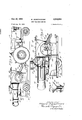
- Figure 4 is a plan view of this invention partly in section and partly broken -away illustrating the general arrangement of the various components.
- Figure 5 is a rear view of the invention partly broken away showing additional details of the general arrangement of components.
- the numeral l10 designates generally the c rop treating device of this invention Ywhile the numeral 11 indicates generally the means of locomotion such as a tractor.
- the numeral 11 indicates generally the means of locomotion such as a tractor.
- 2Vv er is provided on the tractor in the form of an electric generator generally indicated at 12 which is driven by the engine of the tractor 11.
- the tractor 11 is connected to the crop treating device 10 by most any of the commonly known hitching mechanisms generally indicated at 13. f A
- the device 10l comprises a base or frame generally indicated at 14.
- the frame 14 may conveniently be constructed of channel beams 15 welded yto form a conventional type base structure.
- the frame 14 is provided with a laterally extending shaft 16 suitably ⁇ ljournaled to a pair of ground xengaging elements such as wheels 17 for mobility when hitched to a tractor, as shown in Figure 1.
- blowers 18 and 19 Adjacent the forward portion of the frame 14 is mounted one or more air blowers.
- two well-known vane-type blowers, generally indicated at 18 and 19, are employed and positioned so that their respective impeller shafts 20 and 21 are coupled together for driving through bevel gears ⁇ 25 and 26 from a common source of power.
- the blowers 18 and 19 are driven from the power take-01T drive lassociated with the tractor 11 through a driven shaft 22, as best shown in Figures 2 and 4.
- the driven shaft 22 may include a pair of universal joints, one of. which is Ashown at 23, in the usualdrive connection.
- a protective shield or guard 24 is provided for safety termesons so that injury to theoperator is avoided. While one means for driving the blowers 18 and 19 is illustrated, it should be understood that the blowers may be vdriven Yby other means such as one or more electric motors energized kby ⁇ the generator 12 on -the tractor 11.
- the air intake port 27 for the blower 19 is disposed with llongitudinally extending large sectionally constructed air ⁇ ducts 30 and 31mounted securely and communica- .tively vconnected tothe Aexhaust ports 28 and -29, respectively, as shown in Figures 1, 2 -a'nd 4.- 'I-*he lrearward end portions of 'the' ducts 30 ⁇ and 31 may be provided with curved sections -32 and 33,for directing the discharging air from the ducts into the ⁇ atmosphereand lrear'- Wardly. j l.
- the frame 14 Mounted on the -rearward portion' of, the frame 14 are two longitudinally disposed tanks V34 and 35.l
- the tan'k 34 is adapted to carry lwater'or other Vliquid 42 ⁇ while the tank 35 is a reservoir for liquid heating fuel 43.. :In the rearward portion of the ducts 30l and 31-'are mounted respectively liquid or fluid spray orifices or nozzles 36 and 37.
- On the top ofthe tank 35 is mounted a fluid kor water pump 38 driven kby an electric ⁇ motor 39 powered by the generator 12 tof the tractor 11 through lelectric wires 40.
- the pump 38 is vadapted to draw-fluid from ⁇ the tank 34 and deliver the fluid so drawn to the nozzles 36 and 37 through conventional piping 41 under pressure whereby the fluid from lthe tank 34 is discharged in the rearward -portion offthe ductsftl and 31-in Vspray form from the respective nozzles 3 ⁇ 6'and 37.
- a conventionai type fuel combustion or oil burner 44 is mounted therebetween, as illustrated in Figures 2, 4 and 5.
- the burner 44 may include a fuel pump'and an actuating electric ⁇ motor 45 powered by the generator 12 of the tractor 11 'through a conventional connection ofthe electric wires 46.
- - Oil or other fuel 43 is drawnfrom the reservoir 3S by the fuel pump of the burner mechanism 44 through a feed tube 48.
- Each of the ducts 30 and 31 respectively is provided with junctioning small ducts 49 and '50, the rearward ends thereof extending through the walls of the large ducts 30 and 31 to form a venturi arrangement, as best shown in ' Figures 3, 4 and S.
- the forward ends of the ducts ⁇ 49 and 50 may be joined together in a Y-formation to tit over -the combustion chamber of fthe burner 44.
- a pair of receptacles 51 and 52 with respective covers 53 and 54 are suitably mounted on theltop of each respective large air ducts 31 and 32.
- the lower portions of the receptacles 5.1 and '52 are provided with short length conduits 55 and 56 respectively which junction with the respective large ducts 30 and 31 in the manner illustrated in Figures l, 2, 3 and 5. I'he lower end portions of the conduits 55 and 56 are cut at an angle, as best shown in Figures 1 and 3, to form a venturi arrangement.
- the velocity of the air passing through the ducts 30 and 31 creates a partial vacuum within the conduits 55 and 56.
- Each of the conduits is provided with a valve, one of which is shown at 5-8, so that the rate of ow of material from the receptacles S1 and '52 into the ducts 30 and 31 may be controlled.
- a laterally -extending rod 59 connecting the valve 58 in each of the conduits 55 and 56 is provided with a rock arm 60 which is pivotally connected at the outer end thereof at 61- to a control lever 62.
- the lever 62 extends forwardly toward the rearward part of the tractor 11 so that the operator may control the rate of ow of the material through the conduits 55 and 56 from his operating station on the tractor.
- the control lever 62 may be provided with any conventional detent mechanism, generally indicated at 63, for maintaining the lever 62 in a predetermined xed position.
- the material charged into the receptacles 51 and 52 may not necessarily be in powdered form but may also Vbe in liquid formas well.
- the dust or powdered form is more preferable and when the powder is of a type that tends to pack it may be necessary to provide the receptacles with conventional vibrators or shakers (not shown).
- the source of power namely the tractor
- the electric motor 45 of the oil burner v44 is then energized and the oil ignited in any conventional manner.
- the power take-off mechanism of the tractor 111 is engaged in a well-known manner which in turn drives the impellers of the blowers 18 'and 19 in a direction for driving air through the large ducts 30 and 3-1 rearwardly.
- the aspiration of hot gases through the small ducts 49 and 50 from the burner 44 are caused to mix with the cold air from the blowers, resulting in a warm mixture.
- the electric motor 39 is then energized from the generator 12 which drives the water pump 38 in a directionto draw water from the tank 34 and deliver the fluid to the spray nozzles 36 and 37.
- the warm air mixture encounters the water spray causing a portion of the Water to enter ⁇ the gas phase thereby absorbing heat (latent heat of vaporization) while the balance of liquid water is discharged in very small droplets.
- the mixture of warm humid air and small droplets of liquid moisture is discharged into the atmosphere through the open ends of the curved sections 32 and 33 forming a warm moisture laden fog which is dense and tends to lay like a thick blanket in the air.
- the dense low-hanging fog reacts as a heat insulator preventing the sub-freezing upper air layer from reaching the crop and thus prevents frost damage.
- the material in the receptacles 51 and 52 is gradually discharged to the atmosphere along with the warmed air by opening the valves 58 through the control lever 62 permitting the material to mix with the warmed moist ai-r.
- the dust or material from the receptacles gradually adheres to lall parts of the crop and adjacent ground resulting in a much desired uniform dispersement of material particles.
- a tractor propelled mobile crop treating device comprising in combination an ambulatory frame, an air blower mounted on the forward end portion of said frame, said air blower having an air intake port and an air exhaust port, a first air duct mounted longitudinally on said frame, the forward end of said air duct being communicatively connected to said exhaust port of said blower and the rearward end of said duct being open to the atmosphere, said air intake port of said blower being positioned substantially in the same horizontal plane as said iirst air duct, a water tank mounted on said frame, a water pump having an inlet port and an outlet port supported by said frame, said inlet port of said pump being communicatively connected to said tank, a iluid vaporizing spray nozzle mounted internally in the rearward portion of said irst air duct and communicatively connected to the outlet port of said pump, said pump being operable to move water from said tank into said nozzle for discharge vinto said first air duct in spray form, a liquid fuel reservoir mounted on said frame,
- a tractor propelled mobile crop treating device comprising in combination an ambulatory frame, an air blower mounted on one end portion of said frame, said air blower having an air intake port and an air exhaust port, a rst air duct mounted horizontally on said frame, one end of said air duct being communicatively connected to said exhaust port of said blower and the other end being open to the atmosphere, said air intake port of said blower being positioned substantially in the same horizontal plane as said first air duct, a water tank mounted on said frame, a water pump having an inlet port and an outlet port supported by said frame, said inlet port of said pump being communicatively connected to said tank, a vaporizing uid spray nozzle mounted internally in the other end portion of said first air duct and communicatively connected to the outlet port of said pump, said pump being operable to move water from said tank into said nozzle for discharge into said rst air duct in spray form, a fluid fuel reservoir mounted on said frame, a uid fuel combustion burner supported by said frame,
- a tractor propelled mobile crop treating device comprising in combination an ambulatory frame, an air blower mounted on one end portion of said frame, said air blower having an air intake port and an air exhaust port, an air duct mounted longitudinally on said frame, one end of said air duct being communicatively connected to said exhaust port of said blower and the other end being open to the atmosphere, said air intake port being positioned substantially in the same horizontal plane as said air duct, a material containing receptacle mounted above and adjacent one end of said duct, a conduit communicatively connecting said receptacle with said duct, a valve disposed in said conduit, said valve being positioned to control adjustably the rate of discharge of material from said receptacle into said duct, air heating means supported by said frame and communicatively connected for introducing heat continuously into the other end portion of said duct, a iluid spray nozzle mounted in said duct, said nozzle being positioned intermediate said other end portion of said duct and said conduit, a source of water under pressure mounted on
Landscapes
- Life Sciences & Earth Sciences (AREA)
- Engineering & Computer Science (AREA)
- Insects & Arthropods (AREA)
- Pest Control & Pesticides (AREA)
- Wood Science & Technology (AREA)
- Zoology (AREA)
- Environmental Sciences (AREA)
- Catching Or Destruction (AREA)
Description
Oct. 20, 1959 E, JEDRZYKQWSK] 2,908,994
CROP TREATING DEVICE Filed Aug. 28, 195s 2 sheets-sheet 1 E. Jr-:DRzYKowsKl 2,908,994
cRoP TREATING DEVICE oct. 2o, 1959 2 Sheets-Sheet 2 Filed Aug. 28. 195e n Il lllllll' United States Patent Circe CROP TREATING DEVICE Edmund Jedrzykowski, Chicago, Ill., `assignor to International Harvester Company, a corporation of New Jersey This invention relates to a device for treating crops. More in particular this invention relates to a device for simultaneously treating crops with fertilizing or insecticidal materials and preventing frost damage by treating with moist heated air.
Most all types of crops are susceptible to damage by insects and the yield of many types of crops is often enhanced by aan additional treatment of fertilizer during growth. It is also well known that frost damage can be devastating to crops particularly during the early part of the season. This invention contemplates a single mobile Vdevice adapted for preventing frost damage to crops and :at the same time effectively treating the crops with fertilizers and/or insecticides in one operation. Thus the farmers time and labor required are not only-minimized but also his expense is minimized in that but a single machine vis required. The invention also contemplates a device or machine which is adapted to treat crops separately or combinedly any of the abovementioned operations with the same machine. Thus, for example, a farmer may with this invention prevent frost ydamage to a citrus fruit grove and, should he desire, treat the plants `by dusting kwith a powdered insecticide or fertilizer at the same time.
Having the above in mind, it is a prime object of this invention to provide a mobile device capable of simultaneously treating crops with Vmoist heated air and a fertilizer or insecticide in a single operation.
A further object of the invention is to provide a mobile device for Ipreventing frost damage to crops which is also operable for dusting crops with an insecticide or fertilizer.
These and other important objects inherent in and encompassed by the invention will be more readily understood from the ensuing description, .the appended claims line 3-3 of Figure 5.
Figure 4 is a plan view of this invention partly in section and partly broken -away illustrating the general arrangement of the various components.
Figure 5 is a rear view of the invention partly broken away showing additional details of the general arrangement of components.
With continued reference to the drawings, the numeral l10 designates generally the c rop treating device of this invention Ywhile the numeral 11 indicates generally the means of locomotion such as a tractor. In the embodiment selected to illustrate the invention a source of pow- 2,908,994 Patented Oct. `20,1959
2Vv er is provided on the tractor in the form of an electric generator generally indicated at 12 which is driven by the engine of the tractor 11. The tractor 11 is connected to the crop treating device 10 by most any of the commonly known hitching mechanisms generally indicated at 13. f A
The device 10l comprises a base or frame generally indicated at 14. The frame 14 may conveniently be constructed of channel beams 15 welded yto form a conventional type base structure. The frame 14 is provided with a laterally extending shaft 16 suitably `ljournaled to a pair of ground xengaging elements such as wheels 17 for mobility when hitched to a tractor, as shown in Figure 1.
Adjacent the forward portion of the frame 14 is mounted one or more air blowers. In the preferred embodiment illustrated two well-known vane-type blowers, generally indicated at 18 and 19, are employed and positioned so that their respective impeller shafts 20 and 21 are coupled together for driving through bevel gears `25 and 26 from a common source of power. In the embodiment illustrated in the drawings the blowers 18 and 19 are driven from the power take-01T drive lassociated with the tractor 11 through a driven shaft 22, as best shown in Figures 2 and 4. The driven shaft 22 may include a pair of universal joints, one of. which is Ashown at 23, in the usualdrive connection. A protective shield or guard 24 is provided for safety vreasons so that injury to theoperator is avoided. While one means for driving the blowers 18 and 19 is illustrated, it should be understood that the blowers may be vdriven Yby other means such as one or more electric motors energized kby `the generator 12 on -the tractor 11.
The air intake port 27 for the blower 19 is disposed with llongitudinally extending large sectionally constructed air `ducts 30 and 31mounted securely and communica- .tively vconnected tothe Aexhaust ports 28 and -29, respectively, as shown in Figures 1, 2 -a'nd 4.- 'I-*he lrearward end portions of 'the' ducts 30` and 31 may be provided with curved sections -32 and 33,for directing the discharging air from the ducts into the` atmosphereand lrear'- Wardly. j l.
Mounted on the -rearward portion' of, the frame 14 are two longitudinally disposed tanks V34 and 35.l The tan'k 34 is adapted to carry lwater'or other Vliquid 42`while the tank 35 is a reservoir for liquid heating fuel 43.. :In the rearward portion of the ducts 30l and 31-'are mounted respectively liquid or fluid spray orifices or nozzles 36 and 37. On the top ofthe tank 35 is mounted a fluid kor water pump 38 driven kby an electric `motor 39 powered by the generator 12 tof the tractor 11 through lelectric wires 40. The pump 38 is vadapted to draw-fluid from `the tank 34 and deliver the fluid so drawn to the nozzles 36 and 37 through conventional piping 41 under pressure whereby the fluid from lthe tank 34 is discharged in the rearward -portion offthe ductsftl and 31-in Vspray form from the respective nozzles 3`6'and 37. From `rthis it is apparent that air from th'e blower discharged through the open rearward ends of the curved sections l3 2 and-'33 respectively of the lducts 30 ,and 31 lwillbe chargedf'with iinely divided globules of lliquid emanating from @the respective Vnozzles V36- and 37 forming acloudlike 'or' foglike mist discharged into the surrounding atmosphere.
Now in order to heat the air as it is discharged through the ducts 30 and 31 a conventionai type fuel combustion or oil burner 44 is mounted therebetween, as illustrated in Figures 2, 4 and 5. The burner 44 may include a fuel pump'and an actuating electric `motor 45 powered by the generator 12 of the tractor 11 'through a conventional connection ofthe electric wires 46.- Oil or other fuel 43 is drawnfrom the reservoir 3S by the fuel pump of the burner mechanism 44 through a feed tube 48.
Each of the ducts 30 and 31 respectively is provided with junctioning small ducts 49 and '50, the rearward ends thereof extending through the walls of the large ducts 30 and 31 to form a venturi arrangement, as best shown in 'Figures 3, 4 and S. For convenience the forward ends of the ducts `49 and 50 may be joined together in a Y-formation to tit over -the combustion chamber of fthe burner 44. From this it can be seen'that the venturi action of the small ducts -49 and 50 within the large ducts 30 and 31, respectively, tends to draw or aspirate hot air and perhaps the combustion products of the burner 44 at relatively high temperatures through the small ducts 49 and 50 into the large ducts 30 and 31 where the hot gases are mixed with the vcold air from the blowers resulting in a moderately warmed air discharged from the rearward ends of the large ducts into the atmosphere. Of course it should be understood that other forms of heating units would also be satisfactory. For example, a gas burner using compressed fuel gas "like propane or butane may be used. Also, an electric heater powered by the generator 1-2 might be used in which case the heating elements may be incorporated entirely within the ducts 30 and 31 thu-s relieving the necessity of the vsmall ducts y49 and 50 as well as the fuel reservoir 35.
`In order to provide means for dusting the crops with vinsecticides or fertilizers including mixtures thereof, a pair of receptacles 51 and 52 with respective covers 53 and 54 are suitably mounted on theltop of each respective large air ducts 31 and 32. The lower portions of the receptacles 5.1 and '52 are provided with short length conduits 55 and 56 respectively which junction with the respective large ducts 30 and 31 in the manner illustrated in Figures l, 2, 3 and 5. I'he lower end portions of the conduits 55 and 56 are cut at an angle, as best shown in Figures 1 and 3, to form a venturi arrangement. The velocity of the air passing through the ducts 30 and 31 creates a partial vacuum within the conduits 55 and 56.
Each of the conduits is provided with a valve, one of which is shown at 5-8, so that the rate of ow of material from the receptacles S1 and '52 into the ducts 30 and 31 may be controlled. A laterally -extending rod 59 connecting the valve 58 in each of the conduits 55 and 56 is provided with a rock arm 60 which is pivotally connected at the outer end thereof at 61- to a control lever 62. The lever 62 extends forwardly toward the rearward part of the tractor 11 so that the operator may control the rate of ow of the material through the conduits 55 and 56 from his operating station on the tractor. The control lever 62 may be provided with any conventional detent mechanism, generally indicated at 63, for maintaining the lever 62 in a predetermined xed position. i It should be understood, however, the material charged into the receptacles 51 and 52may not necessarily be in powdered form but may also Vbe in liquid formas well. The dust or powdered form is more preferable and when the powder is of a type that tends to pack it may be necessary to provide the receptacles with conventional vibrators or shakers (not shown).
Operation Assuming iirst that an atmospheric temperature drop occurs whereby the selected crop, such as a lcitrus fruit grove, is in danger of frost. These temperature drops usually occur during clear or cloudless nights with little lor no wind. The farmer iills the tank 34 with water and the reservoir 35 with liquid fuel such as oil. He then .charges the receptacles 51 and 52 with insecticidal or fertilizer material with the valves 58 in closed position. The
source of power, namely the tractor, is then started so that the generator 12 is in operation. The electric motor 45 of the oil burner v44 is then energized and the oil ignited in any conventional manner. As soon as the burner 44 is in operation the power take-off mechanism of the tractor 111 is engaged in a well-known manner which in turn drives the impellers of the blowers 18 'and 19 in a direction for driving air through the large ducts 30 and 3-1 rearwardly. The aspiration of hot gases through the small ducts 49 and 50 from the burner 44 are caused to mix with the cold air from the blowers, resulting in a warm mixture. The electric motor 39 is then energized from the generator 12 which drives the water pump 38 in a directionto draw water from the tank 34 and deliver the fluid to the spray nozzles 36 and 37. The warm air mixture encounters the water spray causing a portion of the Water to enter `the gas phase thereby absorbing heat (latent heat of vaporization) while the balance of liquid water is discharged in very small droplets. The mixture of warm humid air and small droplets of liquid moisture is discharged into the atmosphere through the open ends of the curved sections 32 and 33 forming a warm moisture laden fog which is dense and tends to lay like a thick blanket in the air. The dense low-hanging fog reacts as a heat insulator preventing the sub-freezing upper air layer from reaching the crop and thus prevents frost damage. Furthermore, as the heat from the fog blanket slowly dissipates the moisture in the gas phase progressively condenses at which time it gives up its latent heat of vaporization thus providing a continuity of heat evolution. Thus the rate of temperature drop of the fog blanket is greatly retarded. The mobility of the device as drawn by the tractor, of course, serves to spread this warm dense fog over a large area.
Now to further increase the density of the fog blanket as above described, the material in the receptacles 51 and 52 is gradually discharged to the atmosphere along with the warmed air by opening the valves 58 through the control lever 62 permitting the material to mix with the warmed moist ai-r. The dust or material from the receptacles gradually adheres to lall parts of the crop and adjacent ground resulting in a much desired uniform dispersement of material particles.
Having thus described an embodiment of the invention, it can now be seen that the objects of the invention have been fully achieved and it must be understood that changes and modifications may be made which do not depart from the spirit of the invention nor from the scope thereof as defined in the appended claims.
What is claimed is:
l. A tractor propelled mobile crop treating device comprising in combination an ambulatory frame, an air blower mounted on the forward end portion of said frame, said air blower having an air intake port and an air exhaust port, a first air duct mounted longitudinally on said frame, the forward end of said air duct being communicatively connected to said exhaust port of said blower and the rearward end of said duct being open to the atmosphere, said air intake port of said blower being positioned substantially in the same horizontal plane as said iirst air duct, a water tank mounted on said frame, a water pump having an inlet port and an outlet port supported by said frame, said inlet port of said pump being communicatively connected to said tank, a iluid vaporizing spray nozzle mounted internally in the rearward portion of said irst air duct and communicatively connected to the outlet port of said pump, said pump being operable to move water from said tank into said nozzle for discharge vinto said first air duct in spray form, a liquid fuel reservoir mounted on said frame, a liquid fuel combustion burner supported by said frame, a fuel pump mounted adjacent to said burner, said fuel pump being communicatively connected to transfer fuel from said reservoir to said burner, a secondk duct supported by said frame, the forward end of said second duct being communicatively connected to said burner in relation to receive heat and products of combustion from said burner, the rearward end portion of said second duct being connected communicatively with the rearward end portion of said rst duct to form a horizontally disposed venturi positioned rearwardly of said spray nozzle whereby said heat and products of combustion from said burner are discharged into said rst duct, a material containing receptacle mounted above and adjacent the forward end of said rst duct and rearward of said blower, a conduit communicatively connecting the lower portion of said receptacle with said rst duct, a valve disposed in said conduit, said valve being positioned to control adjustably the rate of discharge of material from said receptacle `into said first duct, an externally operable control lever supported by said frame and positioned in connected relation for adjusting said valve, and a source of power mounted on said tractor and connectable to energize said blo-wer and pumps for discharging a mixture of moist heated air with material from the rearward end of said first duct into the atmosphere for contacting and treating said crop.
2. A tractor propelled mobile crop treating device comprising in combination an ambulatory frame, an air blower mounted on one end portion of said frame, said air blower having an air intake port and an air exhaust port, a rst air duct mounted horizontally on said frame, one end of said air duct being communicatively connected to said exhaust port of said blower and the other end being open to the atmosphere, said air intake port of said blower being positioned substantially in the same horizontal plane as said first air duct, a water tank mounted on said frame, a water pump having an inlet port and an outlet port supported by said frame, said inlet port of said pump being communicatively connected to said tank, a vaporizing uid spray nozzle mounted internally in the other end portion of said first air duct and communicatively connected to the outlet port of said pump, said pump being operable to move water from said tank into said nozzle for discharge into said rst air duct in spray form, a fluid fuel reservoir mounted on said frame, a uid fuel combustion burner supported by said frame, a fluid fuel transferring means supported by said frame adapted to transfer iluid fuel from said reservoir to said burner, a horizontally disposed second air duct supported by said frame, said second air duct being positioned in substantially the same horizontal plane as said rst air duct, one end of said second air duct being communicatively connected to said burner for receiving heat therefrom, the other end portion of said second air duct being communicatively connected with the other end portion of said first duct to form a horizontally disposed venturi for discharging heat from said burner and second duct into said rst duct, said spray nozzle being positioned in said first duct between said venturi and said air blower, a material containing receptacle mounted above and adjacent one end of said first air duct, a conduit communicatively connecting the lower portion of said receptacle with said first air duct positioned between said spray nozzle and said air blower, a valve disposed in said conduit, said valve being positioned to control adjustably the rate of discharge of material from saidv receptacle into said first duct, an externally operable control lever supported by said frame and positioned in connected relation for adjusting said valve, and a source of power mounted on said tractor and connectable to energize said blower and pumps for discharging a mixture of moist heated air with material from the other end of said rst duct into the atmosphere for contacting and treating said crop.
3. A tractor propelled mobile crop treating device comprising in combination an ambulatory frame, an air blower mounted on one end portion of said frame, said air blower having an air intake port and an air exhaust port, an air duct mounted longitudinally on said frame, one end of said air duct being communicatively connected to said exhaust port of said blower and the other end being open to the atmosphere, said air intake port being positioned substantially in the same horizontal plane as said air duct, a material containing receptacle mounted above and adjacent one end of said duct, a conduit communicatively connecting said receptacle with said duct, a valve disposed in said conduit, said valve being positioned to control adjustably the rate of discharge of material from said receptacle into said duct, air heating means supported by said frame and communicatively connected for introducing heat continuously into the other end portion of said duct, a iluid spray nozzle mounted in said duct, said nozzle being positioned intermediate said other end portion of said duct and said conduit, a source of water under pressure mounted on said frame, said source of water being connected to said nozzle for discharging vaporized water into said duct, and a source of power mounted on said device and connectable to energize said blower and heating means whereby a mixture of moist heated air with said material is discharged from said other end of said duct into the atmosphere for contacting and treating said crop.
References Cited n the file of this patent UNITED STATES PATENTS 1,372,793 Andersson Mar. 29, 1921 1,495,098 Nelson May 20, 1924 2,201,995 Erickson May 28, 1940 2,315,096 Sanderson Mar. 30, 1943 2,593,275 Daugherty Apr. 15, 1952 2,768,859 Patterson Oct. 30, 1956
Priority Applications (1)
| Application Number | Priority Date | Filing Date | Title |
|---|---|---|---|
| US606676A US2908994A (en) | 1956-08-28 | 1956-08-28 | Crop treating device |
Applications Claiming Priority (1)
| Application Number | Priority Date | Filing Date | Title |
|---|---|---|---|
| US606676A US2908994A (en) | 1956-08-28 | 1956-08-28 | Crop treating device |
Publications (1)
| Publication Number | Publication Date |
|---|---|
| US2908994A true US2908994A (en) | 1959-10-20 |
Family
ID=24428997
Family Applications (1)
| Application Number | Title | Priority Date | Filing Date |
|---|---|---|---|
| US606676A Expired - Lifetime US2908994A (en) | 1956-08-28 | 1956-08-28 | Crop treating device |
Country Status (1)
| Country | Link |
|---|---|
| US (1) | US2908994A (en) |
Cited By (6)
| Publication number | Priority date | Publication date | Assignee | Title |
|---|---|---|---|---|
| US3385521A (en) * | 1965-06-24 | 1968-05-28 | Tecnoma | Air-blast sprayers |
| US3726441A (en) * | 1971-03-19 | 1973-04-10 | Finn Equipment Co | Distributor for fragile particulate materials |
| US3830014A (en) * | 1973-02-14 | 1974-08-20 | Sun & Ski | Tree canopy heater |
| WO1994005429A1 (en) * | 1992-08-26 | 1994-03-17 | Aquaheat Technology, Inc. | Improved apparatus and method for controlling undergrowth |
| US20120138703A1 (en) * | 2010-12-06 | 2012-06-07 | Vandyke Mario | Dual Fan Sprayer |
| US20150208637A1 (en) * | 2012-02-20 | 2015-07-30 | Clarke Mosquito Control Products, Inc. | Insecticide sprayer and rotary spray head assembly |
Citations (6)
| Publication number | Priority date | Publication date | Assignee | Title |
|---|---|---|---|---|
| US1372793A (en) * | 1919-05-14 | 1921-03-29 | Andersson Gustaf Edwin | Means to protect vegetation from frost |
| US1495098A (en) * | 1923-05-11 | 1924-05-20 | A F Ward | Boll-weevil exterminator |
| US2201995A (en) * | 1935-08-30 | 1940-05-28 | John A Erickson | Method for spraying insecticides |
| US2315096A (en) * | 1941-01-07 | 1943-03-30 | Sanderson William | Spraying, dusting, and frost preventing device |
| US2593275A (en) * | 1947-06-26 | 1952-04-15 | Fmc Corp | Spraying and dusting machine |
| US2768859A (en) * | 1954-06-15 | 1956-10-30 | Fmc Corp | Spraying apparatus |
-
1956
- 1956-08-28 US US606676A patent/US2908994A/en not_active Expired - Lifetime
Patent Citations (6)
| Publication number | Priority date | Publication date | Assignee | Title |
|---|---|---|---|---|
| US1372793A (en) * | 1919-05-14 | 1921-03-29 | Andersson Gustaf Edwin | Means to protect vegetation from frost |
| US1495098A (en) * | 1923-05-11 | 1924-05-20 | A F Ward | Boll-weevil exterminator |
| US2201995A (en) * | 1935-08-30 | 1940-05-28 | John A Erickson | Method for spraying insecticides |
| US2315096A (en) * | 1941-01-07 | 1943-03-30 | Sanderson William | Spraying, dusting, and frost preventing device |
| US2593275A (en) * | 1947-06-26 | 1952-04-15 | Fmc Corp | Spraying and dusting machine |
| US2768859A (en) * | 1954-06-15 | 1956-10-30 | Fmc Corp | Spraying apparatus |
Cited By (8)
| Publication number | Priority date | Publication date | Assignee | Title |
|---|---|---|---|---|
| US3385521A (en) * | 1965-06-24 | 1968-05-28 | Tecnoma | Air-blast sprayers |
| US3726441A (en) * | 1971-03-19 | 1973-04-10 | Finn Equipment Co | Distributor for fragile particulate materials |
| US3830014A (en) * | 1973-02-14 | 1974-08-20 | Sun & Ski | Tree canopy heater |
| US5297730A (en) * | 1990-09-14 | 1994-03-29 | Aquaheat Technology, Inc. | Apparatus and method for controlling weeds and undergrowth |
| WO1994005429A1 (en) * | 1992-08-26 | 1994-03-17 | Aquaheat Technology, Inc. | Improved apparatus and method for controlling undergrowth |
| US20120138703A1 (en) * | 2010-12-06 | 2012-06-07 | Vandyke Mario | Dual Fan Sprayer |
| US20150208637A1 (en) * | 2012-02-20 | 2015-07-30 | Clarke Mosquito Control Products, Inc. | Insecticide sprayer and rotary spray head assembly |
| US9491937B2 (en) * | 2012-02-20 | 2016-11-15 | Clarke Mosquito Control Products, Inc. | Insecticide sprayer and rotary spray head assembly |
Similar Documents
| Publication | Publication Date | Title |
|---|---|---|
| US6505437B1 (en) | Weed and plant pests control apparatus and method | |
| US5533676A (en) | Multi-purpose lawn care machine | |
| US4030244A (en) | Metering and spray apparatus for horticultural applications | |
| JPH08503845A (en) | Improved apparatus and method for controlling weeds and undergrowth | |
| US2685146A (en) | Spraying device | |
| US1723955A (en) | Apparatus and method for agricultural spraying | |
| US2908994A (en) | Crop treating device | |
| US10136632B2 (en) | Modified field incinerating arrangement | |
| US5974728A (en) | Method and apparatus for the non-toxic control of insects and weeds | |
| US2745210A (en) | Insecticide distributor | |
| DE19528858C2 (en) | Fire extinguishing robot | |
| US20030147774A1 (en) | Apparatuses and methods for sterilizing soil | |
| US2223597A (en) | Apparatus for protecting vegetation | |
| US2659556A (en) | Method of distributing insecticides or fungicides and steam jet-driven helicopter for performing same | |
| US2012973A (en) | Apparatus for applying insecticidal or fungicidal material | |
| US2671690A (en) | Forced air sprayer and duster | |
| US1282697A (en) | Powder-dusting machine. | |
| US2315096A (en) | Spraying, dusting, and frost preventing device | |
| US2491818A (en) | Vehicular spraying machine | |
| US3140574A (en) | Spraying and mowing apparatus | |
| US2086055A (en) | Spraying apparatus | |
| DE4100221A1 (en) | Destruction of weeds and vermin by electric heaters - towed through spaces into which hot air or vapour is blown between rows of cultivated plants | |
| US2761731A (en) | Agricultural spraying machine | |
| US2686990A (en) | Method of horticultural spraying or dusting | |
| US3216664A (en) | Tractor powered sprayer |