US2906831A - Convertible amplifier to plural channel and to push-pull - Google Patents
Convertible amplifier to plural channel and to push-pull Download PDFInfo
- Publication number
- US2906831A US2906831A US602594A US60259456A US2906831A US 2906831 A US2906831 A US 2906831A US 602594 A US602594 A US 602594A US 60259456 A US60259456 A US 60259456A US 2906831 A US2906831 A US 2906831A
- Authority
- US
- United States
- Prior art keywords
- amplifier
- triode
- push
- pull
- plate
- Prior art date
- Legal status (The legal status is an assumption and is not a legal conclusion. Google has not performed a legal analysis and makes no representation as to the accuracy of the status listed.)
- Expired - Lifetime
Links
- 238000010586 diagram Methods 0.000 description 6
- 230000009977 dual effect Effects 0.000 description 6
- 230000003321 amplification Effects 0.000 description 4
- 238000003199 nucleic acid amplification method Methods 0.000 description 4
- 230000004048 modification Effects 0.000 description 2
- 238000012986 modification Methods 0.000 description 2
- 230000009286 beneficial effect Effects 0.000 description 1
- 239000003990 capacitor Substances 0.000 description 1
- 238000006243 chemical reaction Methods 0.000 description 1
- 230000000694 effects Effects 0.000 description 1
- 230000003334 potential effect Effects 0.000 description 1
- 230000003389 potentiating effect Effects 0.000 description 1
Images


Classifications
-
- H—ELECTRICITY
- H03—ELECTRONIC CIRCUITRY
- H03F—AMPLIFIERS
- H03F3/00—Amplifiers with only discharge tubes or only semiconductor devices as amplifying elements
- H03F3/26—Push-pull amplifiers; Phase-splitters therefor
- H03F3/28—Push-pull amplifiers; Phase-splitters therefor with tubes only
Definitions
- This invention relates to an electrical amplifier, and more specifically ,to an electrical amplifier adapted for easy conversion from a push-pull amplifier into a twochannel amplifier.
- the principles of this invention are particularly applicable to high fidelity audio amplifiers, butcan be applied as well to amplifiers for amplifying other frequencies and amplifiers of lower fidelity.
- a single electrical amplifying system is provided, the circuit for this amplifying system being such that it may be converted by relatively simple switching from a' push-pull amplifier into a two-channel amplifying system, and vice versa.
- this invention comprises a combination of the parts normally found in a push-pull amplifier along with the parts normally found in a two-channel amplifier, but without any substantial duplication. These parts are arranged in a-circuit with appropriate switching means so that the circuit can be converted from a push-pull circuit to a two-channel circuit, and back, simply by the operation of the switching means.
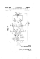
- Figure 1 is a circuit diagram of an amplifier constructed in accordance with the principles of this inven Patented Sept. 29, 1959 2 tion, and with the switching mechanism set so that the amplifier will operate as apush-pull amplifier;
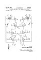
- Figure 2 is a circuit diagram of the same amplifier with the switching mechanism setso that the amplifier willoperate as a two-channel amplifier;
- Figure 3 is a circuit diagram of the same amplifier, connected as a push-pull amplifier, but with'the switching mechanism and inactive parts eliminated so as to simplify the circuit diagram;
- Figure 4 is a similarcircuit diagram ofthe amplifier of this'invention connected as a two-channel amplifier, again with the switching mechanism and inactive parts eliminatedfor simplification.
- the amplifier of this invention may be constructed so as to utilize three dual trio'de thermionic amplifiertubes, 510a and 10b, 11a and 11b, and 12a and '12b, and a pair of single triode amplifier tubes13 :-and 14.
- a rotatable, multiple-contact switch 15a, b, c, d, 2,2 g, h, i, 'j,-kf, l,- m; n; may be used to convert the circuit from'a push-pull circuit to a dualchannel circuit.
- the parts of this switch have been shown scattered about the circuit diagram for convenience, but ordinarily will all comprise a single twoposition, multiple-contact switch. In one position, the switch will make contactsas shown in Figure 1 and in the other position it will make contacts as shown in Figure 2.
- the amplifier is connected for single-channel push-pull operation.
- the input signal which is received at terminals 16 and 17 isapplied between ground and the grid of the triode 10a.
- the cathode of triode 10a is grounded through a bias resistor 18 and supplied with plate potential by a plate resistor 19 from a potential source not shown.
- the output signal goesdi-rec'tly through a switch segment 15a to the grid of the second half of the first triode 1011.
- a second pair ofinput leads 20 and 21 arenot used in the push-pull connection.
- the cathode of the second triode' 10b is grounded through a switch segment 15 and a bias resistor 22, while the plateof thistube'is "supplied with plate potential through a-.- plate resistor 23, which is connected through a'switch segment 15b to a source of plate poten tial not shown.-
- the plate of the second triode 10b is connected through a condenser 24 to the grid of the second halfof thesecond'dualtriode 11b, and the cathode of the second mode 10b is connected through switch segment 15), which segment 15c, and a condenser 25 to the grid of the first half of the second triode 11a.
- resistors 22 and 23 preferably are of the same value of resistance in order that the signal level'to the grids of both triode halves, llaand 11b, will be substantially equal.
- a bridge is formed between the gridsof the two halves of the dual triode 1121 and 11b by two fixed resistors 26 and 27 and a potentiometer 28, all connected in series.
- the slider of the potentiometer 28- is connected to a source of negative bias voltage, not shown and thusthe operation of the potentiometer 28 will adjust the relative potentials of the two grids.
- Plate potential is supplied to the plates of the two 'halveslla and 11b of the second dual; triode through plate.
- resistors 31 and 3-2, respectively, from a plate potential source not shown.
- the cathodes-of tn'ode halves 11a and 11b are directly connected to a common point of negative potentialthro'ugh switch segment 15d; connection shorts ou't series resistors 3 3 and 34, which also connect the cathodes of triode's'l la' and 11b ar'e'biased by the parallel combination of resistors 33 and 34 (shown as a single equivalent resistor 35 in Figure 3).
- the output signals of the second dual triode are carried directly from the plates of the two triodes 11a and 11b to the grids of the two triodes 12a and 12b, respectively, which constitute the two halves of thethird dual triode.
- the plates of triode halvw 12a and 12b are connected directly to the source of plate potent al not shown, while the cathodes are connected to series resistors 36 and 37,with the point of connection between resistors 36 and 37 being connected to the negative bias voltage.
- the third dual triode is employed as two cathode followers so that the cathode output of triode half 12a drives the grid of a triode 13, and the cathode output of triode half 12b drives the. grid of a triode 14, triodes 13 and 14 providing the basis for the fourth and final stage of amplification.
- the cathodes of triodes 13 and 14 are directly grounded.
- the plate of triode 13 is connected through switch segment 15k to one end of the primary of output transformer 39, the other end of the primary of transformer 39 being connected to the plate of triode'14.
- the plate of triode 14 is connected through switch segment 15 to one end ofthe primary of output transformer 38, the other end of the primary of transformer 38 being connected to the plate of triode 13.
- Center taps on the primaries of transformers 38 and 39 are connected through switch segments 151 and 151', respectively, to a source of positive plate potential not shown.
- the net effect is that two output transformers in parallel (shown as a single-equivalent transformer 40 in Figure 3) are connected across triodes 13 and 14.
- the output from the push-pull amplifier is taken between terminal 41 and ground terminal 42, which are connected across the secondary of transformer 38.
- Terminal 41 is connected by means of switch segment 1511' to one end of the secondary of transformer 39, while the other end of the secondary of transformer 39 is .grounded through switch segment 15m.
- the result is that output terminals 41 and 42 are supplied by transformer 39 as well as transformer 38.
- Asecond pair of output terminals 43 and.44 are shorted out by switch segment 15m.
- Feedback for the push-pull amplifier is accomplished by means of a feedback resistor 45 .connected in parallel with a variable condenser 46, the :parallel RC combination being in series with switch segment 15h, so as to connect the secondary of transformer 38 with the cathode of first triode half a.
- the values of resistor 45 and condenser 46 are such as to provide the desired feedback for push-pull operation.
- the system When the rotatable multiple contact switch a, b, c, ,d, e, f, g, h, i, j, k, l, m, n is thrown so as to rotate all the switch segments counterclockwise, thus breaking the connections shown in Figure land at the same time forming the connections shown in Figure 2, the system ,becomes converted into a dual-channel amplifier which operates as two separate and complete amplifiers.
- the first amplifier is constructed around triode halves 10a, 11a, 12a, and single triode 13, while the second amplifier uses triode halves 10b, 11b, 12b, and single triode .14.
- the input for the first amplifier is applied across terminals 16 and 17 between the grid of first diode half 10a and ground, while the input for thesecond amplifier'is applied across terminals 21 and 20 between the grid of secondtriode half 10b and ground, since switch segment 15a nowconnects terminal 21 directly to the grid of triode,10b, leaving the plate of triode 10a disconnected from thegrid of triode 10b.
- the plate of triode 10a remains; biased by plate resistor 19 from a source of potential not shown, while the cathode is grounded through bias resistor 18.
- the alternate position of switch segment 15!; leaves the plate of triode 10b biased through a plate resistor 47 from a source of potential not shown, with resistor 23 being disconnected from the potential source.
- switch segment 15 disconnects resistor 22 from the cathode of triode 10b, and connects in its place a cathode bias resistor 48. Furthermore, switch segment 150 is now positioned so as to disconnect condenser 25 from resistor 22, leaving the plate of first triode half 1011 connected through switch segment 15c and condenser 25 to the grid of second triode half 11a. Also, the plate of first triode half 10b is coupled to the grid of second triode half 11b through condenser 24.
- Switch segment 15g now connects the grid of triode half 11a to the negative bias source through resistor 26, while the grid of triode half 11b is similarly connected through resistor 27 and switch segment 15s. Potentiometer 28 is thus shorted out.
- the movement of switch segment 15d removes the short circuit between the cathodes of triodes 11a and 11b, leaving the cathodes connected by series resistors 33 and 34, with the point connecting these resistors being connected to negative voltage so as to provide bias for the cathode.
- the plates of triode halves 11a and 11b are biased through resistors 31 and 32, respectively, from a source of potential not shown, and the plate outputs from the triodes 11a and 11b are used to drive the grids of third triode halves 12a and 12b, respectively.
- the third triode halves 12a and 12b are connected exactly as before.
- the plates are biased from a source of potential not shown, the cathodes are grounded through resistors 36 and 37, and the cathode follower outputs are used to drive the grids of triodes 13 and 14.
- switch segments 15i, j, k, 1 now disconnects the plate of triode 13 from the primary of transformer 39 and at the same time biases the end of the primary of transformer 39 away from triode 14 to a source of plate potential not shown.
- the new position of switch segment 15 leaves the plate of triode 14 disconnected from the primary of transformer 38 and also biases the end of the primary of transformer 38 away from triode 13 to a source of potential not shown.
- Switch segments 15i and 15l disconnect the center taps on transformers 39 and 38, respectively, from the above-mentioned potential source.
- Switch segment 15m serves to disconnect terminal 44 of the secondary of transformer 39 from ground, while I switch segment 1511 now leaves the other end of the secondary of transformer 39 disconnected from terminal 41 and grounded instead.
- This arrangement provides a separate output for each amplifier, the output for the first amplifier being taken from the secondary of transformer 38 across terminals 41 and 42 and the output for the second amplifier being taken from the secondary of transformer 39 across terminals 43 and 44.
- Feedback for the first amplifier is accomplished by means of parallel resistor 49 and variable condenser 50, which connect the output terminal 42 to the cathode of triode 10a.
- the position of switch segment 15]: is changed so as to disconnect resistor 45 and'condenser 46 and to connect resistor 49 and capacitor 50. This changes the resistance and capacitance values in the feedback network for the first amplifier so that the feedback will be of the desired value for the operation of the first single amplifier, a value difierent from that needed for push-pull operations.
- Parallel resistor 51 and variable condenser 52' are connected from output terminal 44 to the cathode of triode half 10b by means of switch segment 15f in order to provide feedback for the second single amplifier.
- switch segment 15f In pushpull operation, the position of switch segments 15] and 15m serves to short out feedback resistor 51 and condenser 52 along with cathode resistor 48, in order to make feedback for the second single amplifier inoperative.
- a combination comprising first, second, third, and fourth vacuum tubes each having a plate, a grid, and a cathode, a first pair of input terminals, a second pair of input terminals, first and second pairs of output terminals, one output terminal of each of said pairs of output terminals being connected to a common reference potential, and selective circuit means to connect in one position said first, second, third and fourth vacuum tubes, said first and second pairs of input terminals, and said first and second pairs of output terminals as two separate channels of amplification with said first and third vacuum tubes comprising the first and second stages of amplification, respectively, of one channel and said second and fourth vacuum tubes comprising the first and second stages of amplification, respectively, of the other channel, said selective circuit means operable alternatively to connect in a second position said first, second, third, and fourth vacuum tubes, one pair of said input terminals, and one pair of said output terminals as a push-pull amplifier with said first vacuum tube connected as a preamplification stage, said second vacuum tube connected to generate two oppositely phased
Landscapes
- Engineering & Computer Science (AREA)
- Power Engineering (AREA)
- Amplifiers (AREA)
Description
p 1959 J. R. MACDONALD 2,906,831
CONVERTIBLE AMPLIFIER TO PLURAL CHANNEL AND TO PUSH-PULL Filed Aug. 7, 1956 4 Shegts-Sheet 1 INVENTOR- JzmRMaadoiiald v ATTORNEYS Sept. 29, 1959 J. R. MACDONALD CONVERTIBLE AMPLIF IER TO PLURAL CHANNEL AND TO PUSH-PULL Filed Aug. 7, 1956 4 Sheets-Sheet 2 INVENTOR BY I WM WWW ATTORNEYS Sept. 29; 1959 J. R. MACQONALD CONVERTIBLE AMPLIFIER TO PLURAL CHANNEL AND TO PUSH-PULL.
4 Sheets-Sheet 3 Filed Aug. 7, 1956 Q Q HI INVENTOR James EMmdazzald J WM ATTORNEYS Sept. 29, 1959 .1. R. MACDONALD CONVERTIBLE AMPLIFIER T0 PLURAL CHANNEL AND TO PUSH-PULL Filed Au 7, 1956 4 Sheets-Sheet 4 INOR Ja /mas RMacdbzzald %W.&WMM
ATTORNEYS United States Patent CONVERTIBLE AMPLIFIER To PLI'J'RAL CHANNEL AND TO PUSH' PULL James Ross Macdonald, Dallas, Tex., assignor to Texas Instruments Incorporated, Dallas, Tex., a corporation of Delaware Application August 7, 1956, Serial No. 602,594
' 1 Claim. (Cl. 179-471) This invention relates to an electrical amplifier, and more specifically ,to an electrical amplifier adapted for easy conversion from a push-pull amplifier into a twochannel amplifier. The principles of this invention are particularly applicable to high fidelity audio amplifiers, butcan be applied as well to amplifiers for amplifying other frequencies and amplifiers of lower fidelity.
Because of their cost and the amount of space that they occupy, and sometimes because of their weight, it is often desirable to use a single electrical amplifying system for more than one purpose and, if it could be done, it would be beneficial to use a single amplifying system at one time as a push-pull amplifier and at another time as a two-channel amplifier.
An example of such asituation arises when a sound system is installed in which there is but a single source and a single loud speaker. In this case, a push-pull amplifier may be exactly what is wanted. Later, a pair of speakers may be installed, at which time it may be advantageous to use a two-channel amplifier, fed from a single signal source, but with each channel supplying its separate amplifier. This avoids the necessity for a relatively low-impedance, cross-over network at the output of the amplifier and permits the use of a high-impedance, cross-over network-at the input of the amplifiers. Again, a change may be made in the sound system so as to use a binaural input withone input signal going to each of the two channels of the amplifier and each channel feeding its own loudspeaker. There are many other circumstances inwhich the desirability of being able to convert an amplifyingsystem from a pushpull to two-channel operation will be obvious, but the foregoing is a sufficient example.
In accordance with this invention, a single electrical amplifying system is provided, the circuit for this amplifying system being such that it may be converted by relatively simple switching from a' push-pull amplifier into a two-channel amplifying system, and vice versa.
Basically, this invention comprises a combination of the parts normally found in a push-pull amplifier along with the parts normally found in a two-channel amplifier, but without any substantial duplication. These parts are arranged in a-circuit with appropriate switching means so that the circuit can be converted from a push-pull circuit to a two-channel circuit, and back, simply by the operation of the switching means.
Further details and advantages of this novel switching arrangement will be apparent from a consideration of the. appended drawings and the following description, which illustrate and describe the preferred embodiment of the invention. It is to be understood, however, that many modifications and changes in detail may be made within the scope of this invention and that the illustration given hereinafter is simply for the purposes of illustration, and not limitation.
In the appended drawings: 7
Figure 1 is a circuit diagram of an amplifier constructed in accordance with the principles of this inven Patented Sept. 29, 1959 2 tion, and with the switching mechanism set so that the amplifier will operate as apush-pull amplifier;
Figure 2 is a circuit diagram of the same amplifier with the switching mechanism setso that the amplifier willoperate as a two-channel amplifier;
Figure 3 is a circuit diagram of the same amplifier, connected as a push-pull amplifier, but with'the switching mechanism and inactive parts eliminated so as to simplify the circuit diagram;'
Figure 4 is a similarcircuit diagram ofthe amplifier of this'invention connected as a two-channel amplifier, again with the switching mechanism and inactive parts eliminatedfor simplification. I
As illustrated in Figure 1, the amplifier of this invention may be constructed so as to utilize three dual trio'de thermionic amplifiertubes, 510a and 10b, 11a and 11b, and 12a and '12b, and a pair of single triode amplifier tubes13 :-and 14., A rotatable, multiple-contact switch 15a, b, c, d, 2,2 g, h, i, 'j,-kf, l,- m; n; may be used to convert the circuit from'a push-pull circuit to a dualchannel circuit. The parts of this switch have been shown scattered about the circuit diagram for convenience, but ordinarily will all comprise a single twoposition, multiple-contact switch. In one position, the switch will make contactsas shown in Figure 1 and in the other position it will make contacts as shown in Figure 2.
As illustrated in Figures 1 and 3, the amplifier is connected for single-channel push-pull operation. The input signal which is received at terminals 16 and 17 isapplied between ground and the grid of the triode 10a. The cathode of triode 10a is grounded through a bias resistor 18 and supplied with plate potential by a plate resistor 19 from a potential source not shown. The output signal goesdi-rec'tly through a switch segment 15a to the grid of the second half of the first triode 1011. A second pair ofinput leads 20 and 21 arenot used in the push-pull connection.
The cathode of the second triode' 10b is grounded through a switch segment 15 and a bias resistor 22, while the plateof thistube'is "supplied with plate potential through a-.- plate resistor 23, which is connected through a'switch segment 15b to a source of plate poten tial not shown.- The plate of the second triode 10b is connected through a condenser 24 to the grid of the second halfof thesecond'dualtriode 11b, and the cathode of the second mode 10b is connected through switch segment 15), which segment 15c, and a condenser 25 to the grid of the first half of the second triode 11a. At this point is should be noted that resistors 22 and 23 preferably are of the same value of resistance in order that the signal level'to the grids of both triode halves, llaand 11b, will be substantially equal. A bridge is formed between the gridsof the two halves of the dual triode 1121 and 11b by two fixed resistors 26 and 27 and a potentiometer 28, all connected in series. The slider of the potentiometer 28-is connected to a source of negative bias voltage, not shown and thusthe operation of the potentiometer 28 will adjust the relative potentials of the two grids. Plate potentialis supplied to the plates of the two 'halveslla and 11b of the second dual; triode through plate. resistors=31 and 3-2, respectively, from a plate potential source not shown. The cathodes-of tn'ode halves 11a and 11b are directly connected to a common point of negative potentialthro'ugh switch segment 15d; connection shorts ou't series resistors 3 3 and 34, whichalso connect the cathodes of triode's'l la' and 11b ar'e'biased by the parallel combination of resistors 33 and 34 (shown as a single equivalent resistor 35 in Figure 3).
The output signals of the second dual triode are carried directly from the plates of the two triodes 11a and 11b to the grids of the two triodes 12a and 12b, respectively, which constitute the two halves of thethird dual triode. The plates of triode halvw 12a and 12b are connected directly to the source of plate potent al not shown, while the cathodes are connected to series resistors 36 and 37,with the point of connection between resistors 36 and 37 being connected to the negative bias voltage. The third dual triode is employed as two cathode followers so that the cathode output of triode half 12a drives the grid of a triode 13, and the cathode output of triode half 12b drives the. grid of a triode 14, triodes 13 and 14 providing the basis for the fourth and final stage of amplification. The cathodes of triodes 13 and 14 are directly grounded.
The plate of triode 13 is connected through switch segment 15k to one end of the primary of output transformer 39, the other end of the primary of transformer 39 being connected to the plate of triode'14.- Ina similar manner, the plate of triode 14 is connected through switch segment 15 to one end ofthe primary of output transformer 38, the other end of the primary of transformer 38 being connected to the plate of triode 13. Center taps on the primaries of transformers 38 and 39 are connected through switch segments 151 and 151', respectively, to a source of positive plate potential not shown. The net effect is that two output transformers in parallel (shown as a single-equivalent transformer 40 in Figure 3) are connected across triodes 13 and 14.
The output from the push-pull amplifier is taken between terminal 41 and ground terminal 42, which are connected across the secondary of transformer 38. Terminal 41 is connected by means of switch segment 1511' to one end of the secondary of transformer 39, while the other end of the secondary of transformer 39 is .grounded through switch segment 15m. 'The result is that output terminals 41 and 42 are supplied by transformer 39 as well as transformer 38. Asecond pair of output terminals 43 and.44 are shorted out by switch segment 15m. Feedback for the push-pull amplifier is accomplished by means of a feedback resistor 45 .connected in parallel with a variable condenser 46, the :parallel RC combination being in series with switch segment 15h, so as to connect the secondary of transformer 38 with the cathode of first triode half a. The values of resistor 45 and condenser 46 are such as to provide the desired feedback for push-pull operation.
When the rotatable multiple contact switch a, b, c, ,d, e, f, g, h, i, j, k, l, m, n is thrown so as to rotate all the switch segments counterclockwise, thus breaking the connections shown in Figure land at the same time forming the connections shown in Figure 2, the system ,becomes converted into a dual-channel amplifier which operates as two separate and complete amplifiers. The first amplifier is constructed around triode halves 10a, 11a, 12a, and single triode 13, while the second amplifier uses triode halves 10b, 11b, 12b, and single triode .14.
As shown in Figures 2. and 4, the input for the first amplifier is applied across terminals 16 and 17 between the grid of first diode half 10a and ground, while the input for thesecond amplifier'is applied across terminals 21 and 20 between the grid of secondtriode half 10b and ground, since switch segment 15a nowconnects terminal 21 directly to the grid of triode,10b, leaving the plate of triode 10a disconnected from thegrid of triode 10b. The plate of triode 10a remains; biased by plate resistor 19 from a source of potential not shown, while the cathode is grounded through bias resistor 18. The alternate position of switch segment 15!; leaves the plate of triode 10b biased through a plate resistor 47 from a source of potential not shown, with resistor 23 being disconnected from the potential source.
The movement of switch segment 15) disconnects resistor 22 from the cathode of triode 10b, and connects in its place a cathode bias resistor 48. Furthermore, switch segment 150 is now positioned so as to disconnect condenser 25 from resistor 22, leaving the plate of first triode half 1011 connected through switch segment 15c and condenser 25 to the grid of second triode half 11a. Also, the plate of first triode half 10b is coupled to the grid of second triode half 11b through condenser 24.
Switch segment 15g now connects the grid of triode half 11a to the negative bias source through resistor 26, while the grid of triode half 11b is similarly connected through resistor 27 and switch segment 15s. Potentiometer 28 is thus shorted out. In addition, the movement of switch segment 15d removes the short circuit between the cathodes of triodes 11a and 11b, leaving the cathodes connected by series resistors 33 and 34, with the point connecting these resistors being connected to negative voltage so as to provide bias for the cathode. As in the push-pull connection, the plates of triode halves 11a and 11b are biased through resistors 31 and 32, respectively, from a source of potential not shown, and the plate outputs from the triodes 11a and 11b are used to drive the grids of third triode halves 12a and 12b, respectively.
The third triode halves 12a and 12b are connected exactly as before. The plates are biased from a source of potential not shown, the cathodes are grounded through resistors 36 and 37, and the cathode follower outputs are used to drive the grids of triodes 13 and 14.
The cathodes of triodes 13 and 14 remain connected to the negative bias voltage but the plate connections are changed substantially by switch segments 15i, j, k, 1. Switch segment 15k now disconnects the plate of triode 13 from the primary of transformer 39 and at the same time biases the end of the primary of transformer 39 away from triode 14 to a source of plate potential not shown. In a similar manner, the new position of switch segment 15 leaves the plate of triode 14 disconnected from the primary of transformer 38 and also biases the end of the primary of transformer 38 away from triode 13 to a source of potential not shown. Switch segments 15i and 15l disconnect the center taps on transformers 39 and 38, respectively, from the above-mentioned potential source.
Feedback for the first amplifier is accomplished by means of parallel resistor 49 and variable condenser 50, which connect the output terminal 42 to the cathode of triode 10a. The position of switch segment 15]: is changed so as to disconnect resistor 45 and'condenser 46 and to connect resistor 49 and capacitor 50. This changes the resistance and capacitance values in the feedback network for the first amplifier so that the feedback will be of the desired value for the operation of the first single amplifier, a value difierent from that needed for push-pull operations.
Parallel resistor 51 and variable condenser 52' are connected from output terminal 44 to the cathode of triode half 10b by means of switch segment 15f in order to provide feedback for the second single amplifier. In pushpull operation, the position of switch segments 15] and 15m serves to short out feedback resistor 51 and condenser 52 along with cathode resistor 48, in order to make feedback for the second single amplifier inoperative.
Thus, when the switch segments are in the position shown in Figure 2, the system is set for operation as two independent and complete amplifiers, each with its own input and output. When the switch is operated so as to return the switch segments to the position shown in Figure 1, the system once again is available for use as a single-channel, push-pull amplifier. This novel switching arrangement is thus seen to provide either two amplifiers or a single amplifier in substantially one amplifying circuit. At the same time, switching from push-pull to dualchannel operation can be carried out in a most simple and convenient manner.
Although the present invention has been shown and described with reference to a particular embodiment, nevertheless, various changes and modifications obvious to one skilled in the art are within the spirit, scope and contemplation ocf the present invention.
What is claimed is:
A combination comprising first, second, third, and fourth vacuum tubes each having a plate, a grid, and a cathode, a first pair of input terminals, a second pair of input terminals, first and second pairs of output terminals, one output terminal of each of said pairs of output terminals being connected to a common reference potential, and selective circuit means to connect in one position said first, second, third and fourth vacuum tubes, said first and second pairs of input terminals, and said first and second pairs of output terminals as two separate channels of amplification with said first and third vacuum tubes comprising the first and second stages of amplification, respectively, of one channel and said second and fourth vacuum tubes comprising the first and second stages of amplification, respectively, of the other channel, said selective circuit means operable alternatively to connect in a second position said first, second, third, and fourth vacuum tubes, one pair of said input terminals, and one pair of said output terminals as a push-pull amplifier with said first vacuum tube connected as a preamplification stage, said second vacuum tube connected to generate two oppositely phased signals from its cathode and plate and said third and fourth vacuum tubes connected in a push pull arrangement, said selective circuit means comprising first and second impedance connecting the cathodes of said third and fourth tubes, respectively, to a common reference potential, means providing power to all of said vacuum tubes between their plates and a common reference potential, means for applying the signal applied across said first pair of input terminals between the grid and common reference potential of said first tube, means for applying the signal generated at the plate of said second vacuum tube to the grid of said fourth vacuum tube, and switch means applying in a first position the signal applied across said second pair of input terminals between the grid and common reference potential of said second vacuum tube, the sign-a1 generated at the plate of said first tube to the grid of said third tube, the signal generated between the plate and common reference potential of said third tube across said first pair of output terminals, the signal generated between the plate and common reference potential of said fourth tube across said second pair of output terminals, said switch means applying in a second position the signal generated at the cathode of said second tube to the grid of said third tube, the signal generated atthe plate of said first tube to the grid of said second tube, and the signal generated between the plates of said third and fourth tubes across the two of said output terminals which are not connected to a common reference potential, said switch means connecting in said second position the cathodes of said third and fourth tubes together.
References Cited in the file of this patent UNITED STATES PATENTS 2,088,432 Peterson July 27, 1937 2,186,146 Plebanski Jan. 9, 1940 2,684,278 Marchand July 20, 1954 2,706,265 Buehler Apr. 12, 1955 2,761,019 Hall Aug. 28, 1956 FOREIGN PATENTS 670,010 Great Britain Apr. 9, 1952
Priority Applications (1)
| Application Number | Priority Date | Filing Date | Title |
|---|---|---|---|
| US602594A US2906831A (en) | 1956-08-07 | 1956-08-07 | Convertible amplifier to plural channel and to push-pull |
Applications Claiming Priority (1)
| Application Number | Priority Date | Filing Date | Title |
|---|---|---|---|
| US602594A US2906831A (en) | 1956-08-07 | 1956-08-07 | Convertible amplifier to plural channel and to push-pull |
Publications (1)
| Publication Number | Publication Date |
|---|---|
| US2906831A true US2906831A (en) | 1959-09-29 |
Family
ID=24411988
Family Applications (1)
| Application Number | Title | Priority Date | Filing Date |
|---|---|---|---|
| US602594A Expired - Lifetime US2906831A (en) | 1956-08-07 | 1956-08-07 | Convertible amplifier to plural channel and to push-pull |
Country Status (1)
| Country | Link |
|---|---|
| US (1) | US2906831A (en) |
Cited By (5)
| Publication number | Priority date | Publication date | Assignee | Title |
|---|---|---|---|---|
| US3026373A (en) * | 1958-04-30 | 1962-03-20 | Rca Corp | Dual feedback circuit for stereophonic audio-frequency signal amplifier systems |
| US3039062A (en) * | 1959-10-26 | 1962-06-12 | Capitol Records | Balance control system for stereo amplifier |
| US3147345A (en) * | 1961-04-26 | 1964-09-01 | Bell Telephone Labor Inc | Gain selective telephone set |
| US3213198A (en) * | 1962-06-11 | 1965-10-19 | Minnesota Mining & Mfg | Stereophonic-monophonic amplifier |
| GB2416438A (en) * | 2004-07-19 | 2006-01-25 | Randall Smith | Vacuum tube power amplifier switchable between push-pull and single ended configurations |
Citations (6)
| Publication number | Priority date | Publication date | Assignee | Title |
|---|---|---|---|---|
| US2088432A (en) * | 1934-02-17 | 1937-07-27 | Rca Corp | Frequency converter circuit |
| US2186146A (en) * | 1938-03-08 | 1940-01-09 | Radio Patents Corp | Side band suppression system |
| GB670010A (en) * | 1948-12-31 | 1952-04-09 | Gen Electric Co Ltd | Improvements in or relating to electrical signalling apparatus |
| US2684278A (en) * | 1948-03-12 | 1954-07-20 | Technicon Cardiograph Corp | Sensitivity control for multichannel recording apparatus |
| US2706265A (en) * | 1951-09-20 | 1955-04-12 | Maurice E Buehler | Multi-commutated channel amplifier |
| US2761019A (en) * | 1950-10-18 | 1956-08-28 | Cecil T Hall | Direct coupled power amplifiers |
-
1956
- 1956-08-07 US US602594A patent/US2906831A/en not_active Expired - Lifetime
Patent Citations (6)
| Publication number | Priority date | Publication date | Assignee | Title |
|---|---|---|---|---|
| US2088432A (en) * | 1934-02-17 | 1937-07-27 | Rca Corp | Frequency converter circuit |
| US2186146A (en) * | 1938-03-08 | 1940-01-09 | Radio Patents Corp | Side band suppression system |
| US2684278A (en) * | 1948-03-12 | 1954-07-20 | Technicon Cardiograph Corp | Sensitivity control for multichannel recording apparatus |
| GB670010A (en) * | 1948-12-31 | 1952-04-09 | Gen Electric Co Ltd | Improvements in or relating to electrical signalling apparatus |
| US2761019A (en) * | 1950-10-18 | 1956-08-28 | Cecil T Hall | Direct coupled power amplifiers |
| US2706265A (en) * | 1951-09-20 | 1955-04-12 | Maurice E Buehler | Multi-commutated channel amplifier |
Cited By (6)
| Publication number | Priority date | Publication date | Assignee | Title |
|---|---|---|---|---|
| US3026373A (en) * | 1958-04-30 | 1962-03-20 | Rca Corp | Dual feedback circuit for stereophonic audio-frequency signal amplifier systems |
| US3039062A (en) * | 1959-10-26 | 1962-06-12 | Capitol Records | Balance control system for stereo amplifier |
| US3147345A (en) * | 1961-04-26 | 1964-09-01 | Bell Telephone Labor Inc | Gain selective telephone set |
| US3213198A (en) * | 1962-06-11 | 1965-10-19 | Minnesota Mining & Mfg | Stereophonic-monophonic amplifier |
| GB2416438A (en) * | 2004-07-19 | 2006-01-25 | Randall Smith | Vacuum tube power amplifier switchable between push-pull and single ended configurations |
| GB2416438B (en) * | 2004-07-19 | 2009-04-29 | Randall Smith | Vacuum tube power amplifier switchable between push-pull and single ended configurations |
Similar Documents
| Publication | Publication Date | Title |
|---|---|---|
| US2464353A (en) | Electronic switching system | |
| US2424893A (en) | Amplifier circuits | |
| US2200055A (en) | High impedance attenuator | |
| US2121434A (en) | Amplifier with oscillation producing adjustment | |
| US2590104A (en) | Direct-coupled amplifier | |
| US2289301A (en) | Phase inversion circuit | |
| US2906831A (en) | Convertible amplifier to plural channel and to push-pull | |
| US2301373A (en) | Multichannel telegraph system | |
| US2737547A (en) | Cathode follower circuits | |
| US2324279A (en) | Amplifier | |
| US2802907A (en) | Distortionless audio amplifier | |
| US2570225A (en) | Series electronic switch | |
| US2638512A (en) | Direct coupled amplifying system | |
| US2101688A (en) | Tone control device | |
| US2464594A (en) | Phase and amplitude control circuit for wide band amplifiers | |
| US2288600A (en) | Electrical device | |
| US2256512A (en) | Dual channel amplifier | |
| US2266168A (en) | Amplifier | |
| US2979665A (en) | Push-pull amplifier | |
| US2860192A (en) | Amplifiers | |
| US2595444A (en) | Amplifier | |
| US3213198A (en) | Stereophonic-monophonic amplifier | |
| US2490727A (en) | Direct-current voltage amplifier | |
| US2338342A (en) | Amplifier circuit | |
| US2682607A (en) | Amplifier |