US2906821A - Printing telegraph apparatus - Google Patents
Printing telegraph apparatus Download PDFInfo
- Publication number
- US2906821A US2906821A US504851A US50485155A US2906821A US 2906821 A US2906821 A US 2906821A US 504851 A US504851 A US 504851A US 50485155 A US50485155 A US 50485155A US 2906821 A US2906821 A US 2906821A
- Authority
- US
- United States
- Prior art keywords
- type
- carrier
- printing
- arm
- lever
- Prior art date
- Legal status (The legal status is an assumption and is not a legal conclusion. Google has not performed a legal analysis and makes no representation as to the accuracy of the status listed.)
- Expired - Lifetime
Links
- 230000033001 locomotion Effects 0.000 description 48
- 238000010586 diagram Methods 0.000 description 14
- 230000000875 corresponding effect Effects 0.000 description 13
- 239000011435 rock Substances 0.000 description 11
- 230000000694 effects Effects 0.000 description 6
- 230000002730 additional effect Effects 0.000 description 2
- 230000000977 initiatory effect Effects 0.000 description 2
- 241000972773 Aulopiformes Species 0.000 description 1
- NVNLLIYOARQCIX-MSHCCFNRSA-N Nisin Chemical compound N1C(=O)[C@@H](CC(C)C)NC(=O)C(=C)NC(=O)[C@@H]([C@H](C)CC)NC(=O)[C@@H](NC(=O)C(=C/C)/NC(=O)[C@H](N)[C@H](C)CC)CSC[C@@H]1C(=O)N[C@@H]1C(=O)N2CCC[C@@H]2C(=O)NCC(=O)N[C@@H](C(=O)N[C@H](CCCCN)C(=O)N[C@@H]2C(NCC(=O)N[C@H](C)C(=O)N[C@H](CC(C)C)C(=O)N[C@H](CCSC)C(=O)NCC(=O)N[C@H](CS[C@@H]2C)C(=O)N[C@H](CC(N)=O)C(=O)N[C@H](CCSC)C(=O)N[C@H](CCCCN)C(=O)N[C@@H]2C(N[C@H](C)C(=O)N[C@@H]3C(=O)N[C@@H](C(N[C@H](CC=4NC=NC=4)C(=O)N[C@H](CS[C@@H]3C)C(=O)N[C@H](CO)C(=O)N[C@H]([C@H](C)CC)C(=O)N[C@H](CC=3NC=NC=3)C(=O)N[C@H](C(C)C)C(=O)NC(=C)C(=O)N[C@H](CCCCN)C(O)=O)=O)CS[C@@H]2C)=O)=O)CS[C@@H]1C NVNLLIYOARQCIX-MSHCCFNRSA-N 0.000 description 1
- 108010053775 Nisin Proteins 0.000 description 1
- 241001387976 Pera Species 0.000 description 1
- 102000003800 Selectins Human genes 0.000 description 1
- 108090000184 Selectins Proteins 0.000 description 1
- 150000001768 cations Chemical class 0.000 description 1
- 238000010276 construction Methods 0.000 description 1
- 230000001276 controlling effect Effects 0.000 description 1
- 238000001514 detection method Methods 0.000 description 1
- 238000006073 displacement reaction Methods 0.000 description 1
- 239000004309 nisin Substances 0.000 description 1
- 235000010297 nisin Nutrition 0.000 description 1
- 229920000136 polysorbate Polymers 0.000 description 1
- AAEVYOVXGOFMJO-UHFFFAOYSA-N prometryn Chemical compound CSC1=NC(NC(C)C)=NC(NC(C)C)=N1 AAEVYOVXGOFMJO-UHFFFAOYSA-N 0.000 description 1
- 229920005989 resin Polymers 0.000 description 1
- 239000011347 resin Substances 0.000 description 1
- 235000019515 salmon Nutrition 0.000 description 1
- 238000013022 venting Methods 0.000 description 1
Images


Classifications
-
- H—ELECTRICITY
- H04—ELECTRIC COMMUNICATION TECHNIQUE
- H04L—TRANSMISSION OF DIGITAL INFORMATION, e.g. TELEGRAPHIC COMMUNICATION
- H04L17/00—Apparatus or local circuits for transmitting or receiving codes wherein each character is represented by the same number of equal-length code elements, e.g. Baudot code
- H04L17/16—Apparatus or circuits at the receiving end
- H04L17/26—Apparatus or circuits at the receiving end using aggregate motion translation
Definitions
- start-stop signal recording mechanism and aggregate motion type positioning mecha- Which in combination constitute the major part of a start sto'p receiving telegraph apparatus.
- the type carrier supports a number of horizontal rows of type faces and the aggregate motion mechanism serves to move the type carrier both in a vertical direction so as tob'ring a selected row of type facesto'the printing level and in a horizontal direction' so as to bring a selected type faeein' the row into the printing position;
- the type carrier is then'lield in this position until repositioned in accordance with the subsequent signal character received; Under these conditions, the type carrier is often left in apositio'n in which the" last character printed is completely obsctired from view by the type carrier. This is an objectibnal feature and constitutes a major reason operating ag'aiiistthe' use of such type positioning mechanism.
- the mechanism controlling the vertical movements' of the type carrier is tripped s'o'a's to lower the type carrier toits lowest position if it is not already in it. As soonas'this position is reached, the last printed character becomes visible over the top of thetype'carrier and the disadvantage just mentioned is overcome.
- the detection of theidle condition is preferably arranged to trip the clutches so as' to turn the mechanism into the'positionjcorresponding to the lowest position of the'typecariier if it is not already in this position.
- the tripping operation may'conveniently becontrolled by three separate cams so' th'at onlywhen'all three are'in 'a position corresponding to the idle condition is'the bar released;
- the type carrier requires to have both a vertical and horizontal movement, and for this purpose it may be arranged-t slide in a vertical direction and to turn about a vertical axis to produce the horizontal movement of the type members.
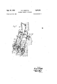
- Figure l is a diagrammatic perspective view ofthe operating mechanism, including aggregate motion mechanism and'the type carrier;
- Figure'2 is a portion of Figure 1 to an enlargedscale
- code permutation members I 2', 3, 4 and" 5" are controlled by means of signal selectin'g mechanism, not shown, which acts by way of pivoted vanes V1 to VSE
- the corresponding code permutation member is moved longitudinally between a space position; which is' t-lie left' hand'oi in two positions shown in the drawing and a mark pass 7 n; which is the right-hand'posit-ion.
- Each member ispro ded with a pivoted extension E1" to formed with an opening 6 through which passes the erdssmember' 7 of a' cradl s" pivoted at 9.
- Theop'enings 6 are eij iigated so as to allow for the'longitudinal moveterrorismit 0f the pei'iniitationmeinbers and their extensions.
- the cradle 8 is provided with a control arm 10 coop ingwitna 11 which once per cycle'of operation reeks the cradle Ste lift the extensions and rock" them about their pivots.
- a control arm 10 coop ingwitna 11 which once per cycle'of operation reeks the cradle Ste lift the extensions and rock" them about their pivots.
- therei's'fa'further member 15 provided for ease-shifting; and controlled by a vane 'V15 described in mere'detaii in c'ep'endin application Ser. No: 504,852, filediApril" 29 1953.
- each of the eitensions has'an upturned heel portion H1 to H5 and H15, which, when the cradle 8 isrocked, c'o-o'pera t'es either'with aspace release detent S1 to S5 and S15- or with a' mark release deteiit M1 to M5 and M15.
- space felease deten't-s' are each pivoted" at 16 and themark release detents are pivoted at 17', the 'two beingpulled together against stops'"18"and 19 respectively by means of a tension spring 20;
- Each space release deten-t is formed at its upper end with-an intiirried lip L1 to L5 and L15.
- the ge'arwheel's are mounted to turn freely on a cbnstantly driven shaft 25 which turns in a clockwise direction as seen in the figure.
- a number of ratchet wheels R1 to R5 and R15 arefixed'to this shaft so as totur -n with it, each ratchet wheel being situated adjacent the corresponding gearwheel so as to co-operate' with the corresponding pawl 21;
- each ge'arwheel in a 1:1' ratio i s -a series of crank gsarwneelscol' to CG'S-and CG1 5, each turning on a stud 30.
- Each crank gearwheel has a crank pin 31 which carries one end of a connecting link 32, the other end of which is connected to a bellcrank lever.
- crank gearwheels CG3, CG4, CG5 and CG15 constitute part of an aggregate motion mechanism indicated generally at 34.
- crank gearwheel CG3 rocks one arm 40 of a bellcrank lever, of which the other arm 41 is provided with a pin 42 acting in a fork 43 on a further bellcrank lever 44.
- the crank gearwheel CG4 rocks one arm 45 of a bellcrank lever, of which the other arm 46 carries the pivot 47 of the lever 44. In this way the rocking movements of both arms 41 and 46 are added together in the motion of the bellcrank lever 44.
- the bellcrank lever 44 is provided with a fork 48 co-operating with a pin 49 mounted on the upper end of a further bellcrank lever 50.
- This is pivoted at 51 on one arm 52 of another bellcrank lever, of which the other arm 53 is rocked by the crank gearwheel CG5 so that the movement of the lever 50 aggregates the motions of the crank gearwheels CG3, CG4 and CGS.
- the lever 50 has a fork 55 co-operating with a pin 56 on the lower end of a further bellcrank lever 57, which in its turn is pivoted at 58 to one arm 59 of a bellcrank lever, of which the other arm 60 is rocked by the crank gearwheel CG15.
- the ratios of the various lever arms are so selected that if a half revolution of the gearwheel G3 is considered as giving the rack unit motion, then a half revolution of the gearwheel G4 will give two units of motion, a half revolution of the gearwheel G5 will give four units of motion and a half revolution of the gearwheel G15 will give eight units of motion. If the movement is from a space release detent to a mark release detent, then the motion produced will be in one direction and if it is from a mark release detent to a space release detent, then it will be in the opposite direction. Thus it will be understood that for any particular combination of settings of the members 3, 4, 5 and 15, there will be a corresponding position of the toothed rack 64. There will in fact be sixteen such combinations and this will lead to sixteen different positions of the rack.
- Movements of the rack 64 are transmitted to a toothed Wheel 70 mounted on a spindle 71, on the other end of which is a further toothed wheel 72 meshing with a third wheel 73.
- the toothed wheel 73 is mounted on a shaft 74 formed with a spline or keyway 75 on which slides a gearwheel 76 formed with spiral teeth.
- the wheel 76 has a small key 77 co-operating with the keyway 75 so that although the wheel can slide on the shaft 74, it cannot turn.
- the spiral gear 76 meshes with a gear sector 78 also provided with spiral teeth and turning about a vertical axis on a splined shaft 79.
- a mounting 82 for a type head, indicated generally at 83, is provided with a key 84 co-operating with a keyway 85 on the shaft 79 so that the mounting is free to slide but not to turn on the shaft. Consequently longitudinal movements of the rack 64 are transmitted via the spindle 71, shaft 74 and the shaft 79 to the mounting 82 and hence to the type head itself 83. 'Ihu's for each of the sixteen longitudinal positions of the rack 64, there is a corresponding angular position of the type head 83.
- the type head is provided with four horizontal rows of type members, each row containing sixteen type members so that each of the sixteen angular positions of the type head brings one of the members in a row into the printing position.
- the angular position of the type head is controlled in accordance with the positions of the members E3, E4, E5 and E15.
- the two members E1 and E2 control a further aggregate motion mechanism indicated generally at which in its turn controls the vertical movements of the type head 83.
- the crank gearwheel CGI rocks one arm 91 of a bellcrank lever turning on the shaft 33 and of which the other arm 92 is connected through a pin and fork connection to one arm 93 of a further bellcrank lever.
- This further bellcrank lever is pivoted at 94 to a bellcrank lever 95, which is rocked by the crank gearwheel CG2 so that the movement of the arm 96 of the bellcrank lever aggregates the motions of the crank gearwheels CGI and CG2.
- the proportions of the levers are such that a half revolution of the crank gearwheel CGl pro prises double the displacement produced by a half revolution of the crank gearwheel CG2. In this way the four combinations of the different positions of the members E1 and E2 lead to four different positions of the bellcrank arm 96.
- the arm 96 is connected by a pin and fork connection 97 to a cradle 98 pivoted at 99.
- the crosspiece 100 of this cradle extends across the width of the machine and thus controls the movements of a forked lever 101 turning about a fixed pivot 102.
- the opposite end of the lever 101 is pivoted to a stud 103 on the mounting 82 for the type head 83.
- rocking movements of the cradle 98 are transmitted to the lever 101 and serve to raise and lower the mounting 82 on the splined shaft 79.
- each of the four positions of the aggregate motion mechanism produces a corresponding vertical position of the type head 83 and serves to bring one of the rows of type members up to the printing level.
- each type member As each type member is brought to the printing position, it is actuated by a mechanism described in the copending application Ser. No. 504,853, filed April 29, 1955, now Patent No. 2,876,280.
- a hammer strikes the rear of the type member, which is slidable in its support, and causes the type member to act via a type ribbon, not shown, to print on a sheet of paper, also not shown, supported by a roller 105.
- the type head 83 When the type head 83 is in its uppermost position, which is necessary to bring the lowest row of type members into the printing position, the type head itself tends to obscure what has just been printed on the paper.
- the mechanism for this purpose is controlled by a trip bar sliding in a guide 111 and urged to the right as seen in the drawing by means of a spring 112.
- the bar is normally latched in its position to the left by meansof two separate catches.
- a catch 113 is formed on an arm 114 pivoted at 115. The catch 113 when in its uppermost position engages a shoulder 116 on the bar 110 but when in its lowered position is clear of the shoulder 116 so as to allow the bar 110 to move to the right.
- a catch 116a formed on an arm 117 pivoted atj118 engages a shoulder 119 on the arm 110.
- the arm 117 moves in a counter-clockwise direction from the position shown in the drawings, it treat the shoirlder 119, and provided the catch 113 is also in itslower-position, the bar 110 moves to the right under the influence arm 131 rocks the two space release detents also fin a counter-clockwise direction so as to allow the gearwheels G1 and G2 to turn into a position in whichthe transverse arms a are in engagement with the mark release detents.
- This operates the aggregate motion mechanism 90 so as to move the type carrier 83 into its lowermost position as required.
- the actuation of the cradle 127 has no additional effect.
- FIG. 3 illustrates the sequence and timing of the operations of different parts of the mechv anism as a whole.
- the diagram A illustrates the opera tion of a cam 140, which may be referred to as the OE normal cam, and which is mounted on the signal selector cam shaft 141.
- a cam 140 which may be referred to as the OE normal cam
- an 'arm 142 pivoted at143 is displaced to a maximum extent by a projection 144 on the cam.
- the left-hand end of the arm 142 drops and remains stationary until it is lifted again by the projection 145.
- This cam rotates intermittently as long as a signal is being received by the apparatus. That is, this cam turns through half a revolution after receipt of each start signal by the apparatus.
- the type carrier reset cam shaft 160 is released as seen from diagram H. i Th s causes a cam 161 to rotate,.which is formed with a pair of recesses 162 and .163. Just before the end of its cycle.
- the cam 161 allows the lever 11' 7, which cooperates with it to rock in a counter-clockwise direction under the control of a spring 163a. As can be seen from diagram H, this takes place at an instant aboutElSQmilliseconds from the instant of release of the selecting cam shaft 141. If, between these two instants, no signal addi tional to that causing release of the camshaft 141-has 6 611 more without aiiy s'ig'ii'al being received, is deteeted, the type carrier is lo'wered to render the'last pr'in'ted character clearly visible.
- Diagrams A and C have already been described, and diagiarn B shows the operation ofjthe trip for the cam shaft, whoseoperation issho'wn in diagram C.
- Diagram D shows the operation of the permutation tr'ansfe r'carn.
- Diagrains E and show the'operation respectively of cams 31 9 an'd 315 described in copending application Ser. No. 504,852, 'filed April 29, 1955.
- Diagram G shows the operation of the cam l l-"co'ntrolling the cradle 10.
- Diagram H shows the operation of the cam 161.
- Diagram I shows the operation of the gearbeen received, then both the cams 140 and 147 are in their rest position so that the catch 113 is in its lower position.
- the trip bar 110 is released to lower the type carrier as previously described.
- diagrams K and L' show-the operations respectively of a print t'rip cam shaft and a printing cam shaft described in copending application Ser. No. 504,853, filed April 29, 1955. Iclaim: 1 1.
- thecoinbina tion of a type carrier having 'a plurality of rows of type faces supported thereon, carrierope'r'ating mechanism controlled by received signals 'andpperating to move a positive mechanical rriaiiner said ea'rr'ier in a direction perpendicular to said rows to bring a selected we dine printing level and in another direction to bring in a positive mechanical manaerasei'ecte type face, in sa'id selected row into the printing position, sensing means'cohtrolled by received signals for sensing the time elapsed since receiving 'the previous signal and responding only to a no-signal condition longer than the normal interval between two adjacent-signals, and tripping means controlled by said sensing means for tripping said carrier opcrating mechanism to effect movement of said carrier in a positive mechanical manner intoa disposition to expose to view the previously printed characters.
- said carrieroperating mechanism comprises a plurality of clutches controlled by received signals and operating an aggregate motion mechanism to move said carrier in said perpendicular direction, said tripping means acting on said clutches to eifect movement of said carrier into said disposition.
- said tripping means comprising a bar and said sensing means including three cams which release said bar to effect tripping only when all three cams are in a position corresponding to a no-signal condition longer than the said interval.
- a combination according to claim 5 said disposition being a positionin which one of said rows of type faces is at the printing level.
- said type carrier is of the cylindrical type mounted with its axis in a vertical position, said carrier being mounted to move in a vertical direction to bring a selected row of type face to the printing level, and being turnable about its vertical axis to bring the selected type face of the selected row into the printing position, and said tripping means acting on said clutches to effect movement of said carrier into its lowermost position.
- said carrier operating mechanism comprises a plurality of clutches controlled by received signals and operating an aggregate motion mechanism to move said carrier in said perpendicular direction, said tripping means acting on said clutches to eflfect movement of said carrier into said disposition.
- a combination according to claim 8 wherein said type carrier is of the cylindrical type mounted with its axis in a vertical position, said carrier being mounted to move in a vertical direction to bring a selected row-of type face to the printing level, and being turnable about its vertical axis to bring the selected type face of the selected row into the printing position, said disposition being the lowermost position of said carrier.
- said tripping means comprising a bar
- said sensing means including three cams which release said bar to effect tripping only when all three cams are in a position corresponding to a no-signal condition longer than the said interval.
- a type carrier having a plurality of rows of type faces supported thereon
- carrier operating mechanism controlled by received signals and operating to move in a positive mechanical manner said carrier in a direction perpendicular to said rows to bring a selected row to the printing level and in another direction to bring in a positive mechanical manner a selected type face in said selected row into the printing position
- sensing means controlled by received signals for sensing the time elapsed since receiving the previous signal and responding only to a no-signal condition longer than the normal interval be tween two adjacent signals
- means controlled by 'said sensing means for effecting movement of said carrier in a positive mechanical manner into a disposition to expose to view the previously printed characters.
- a type carrier having a plurality of rows of type faces supported thereon
- carrier operating mechanism controlled by received signals and operating to move said carrier in a direction perpendicular to said rows to bring a selected row to the printing level and in another direction to bring aselected type face in said selected row into the printing position
- at least three cams arranged to turn, one after another, from one restposition to another, the first of said cams having its turning movement initiated by receipt of each signal and the last of said cams coming to rest apredetermined period later
- stop means held in an active position by said cams whenever turning but moved into an inactive position whenall said cams'take up their rest positions
- tripping means arranged to be actuated at an instant which occurs a predetermined time after said period and which is later than the time at which a signal would be received which is following immediately after that initiating the turning movement of the said first cam, the said tripping means being connected .to 'trip said carrier operating mechanism to effect movement of said carrier into a disposition i
- a type carrier having a plurality of rows of type faces supported thereon
- carrier operating mechanism con trolled by received signals and operating to move said carrier in a direction perpendicular to said rows to bring a selected row to the printing level and in another direction to bring a selected type face in said selected row into the printing position
- at least three cams arranged to turn, one after another, from one rest position to another, the first of said cams having its turning movement initiated by receipt of each signal and the period between this initiation and the coming to rest of the last cam being greater than the time elapsing between the beginnings of adjacent signals
- stop means held in an active position by said cams Whenever turning but moved into an inactive position when all said cams take up their rest positions, and tripping means arranged to be actuated a predetermined time after said period and being connected to trip said carrier operating mechanism to effect movement of said carrier into a disposition to expose to view the previously printed characters, the said stop means being arranged so that when in said active position said stop means
- said sensing means including at least three cams arranged to turn, one after another, from one rest position to another, the first of said cams having its turning movement initiated by receipt of each signal and the last of said cams coming to rat a predetermined period later.
- said carrier operating mechanism comprising a plurality of clutches controlled both by received signals and by said tripping means, and aggregate motion mechanism controlled through said clutches and connected to move said type carrier in a positive mechanical manner both when positioning said type carrier for printing and when moving said type carrier into the said disposition.
- said carrier operating mechanism comprising a plurality of clutches controlled both by received signals and by said tripping means, and aggregate motion mechanism controlled through said clutches and connected to move said type carrier in a positive mechanical manner both when positioning said type carrier for printing and when moving 'said type carrier into the said disposition.
- said type carrier is of the cylindrical type mounted with its axis in a vertical position, said carrier being mounted to type faces to the printing level and being turnable about its vertical axis to bring the selected type face of the selected row into the printing position.
- said tripping means including a bar having a pair of projections
- said stop means including an arm controlled by one cam and arranged to engage one of the said projections
Landscapes
- Engineering & Computer Science (AREA)
- Computer Networks & Wireless Communication (AREA)
- Signal Processing (AREA)
- Transmission Devices (AREA)
- Character Spaces And Line Spaces In Printers (AREA)
Description
Sept 1959 R. G. GRIFFITH 2, 06,
PRINTING TELEGRAPH APPARATUS Filed April'29. 1955 3 Sheets-Sheet 1 2/ 52%; 2,667 /29 52 2 2 i 420.1 I W6 /s5//2/ 26/22/27 20 .(4 L I I n ventbr Attorney Sept; 29, 1959 Filed April 29. 1955 R. G. GRIFFITH PRINTING TELEGRAPH APPARATUS 3 Sheets-Sheet 2 lnven lor 4w wqLamh-t A Home y p 29, 1959 R. G. GRIFFITH 2,906,821
PRINTING TELEGRAPH APPARATUS Filed April 29. 1955 3 Sheets-Sheet 3 fiA Inventor flak/5W By 1442! Attorney United States Patent O 2,906,821 7 PRINTING TELEGRAPH APPARATUS Ronald George Grifiith, Mount RoyaL-Montreal, Quebec, Canada Applica fibii A ril 29, 1 955, SiiHI NIB 5045851 Claims priority,- appli'cation Great Britain May 3, 1954 21 (ilaims. (Cl. 178---34Y This invention relates to start-stop printing telegraph apparatus and is particularly concerned with type selectiiig and positioning rnechanisrnsuch is described in British patent specifications Nos. 439,745 and 441,090. These specifications describe start-stop signal recording mechanism and aggregate motion type positioning mecha- Which in combination constitute the major part of a start sto'p receiving telegraph apparatus. In such startstop receivingapparatus, the type carrier supports a number of horizontal rows of type faces and the aggregate motion mechanism serves to move the type carrier both in a vertical direction so as tob'ring a selected row of type facesto'the printing level and in a horizontal direction' so as to bring a selected type faeein' the row into the printing position; The type carrier is then'lield in this position until repositioned in accordance with the subsequent signal character received; Under these conditions, the type carrier is often left in apositio'n in which the" last character printed is completely obsctired from view by the type carrier. This is an objectibnal feature and constitutes a major reason operating ag'aiiistthe' use of such type positioning mechanism.
According to the present invention', as soon as a predetermined idle conditionis detected, the mechanism controlling the vertical movements' of the type carrier is tripped s'o'a's to lower the type carrier toits lowest position if it is not already in it. As soonas'this position is reached, the last printed character becomes visible over the top of thetype'carrier and the disadvantage just mentioned is overcome. If the vertical movements of the type carrier are controlled by anaggregate'niotioninechanism driven through clutches, the detection of theidle condition is preferably arranged to trip the clutches so as' to turn the mechanism into the'positionjcorresponding to the lowest position of the'typecariier if it is not already in this position.
The tripping operation may'conveniently becontrolled by three separate cams so' th'at onlywhen'all three are'in 'a position corresponding to the idle condition is'the bar released; I As previously mentioned; the type carrier requires to have both a vertical and horizontal movement, and for this purpose it may be arranged-t slide in a vertical direction and to turn about a vertical axis to produce the horizontal movement of the type members.
. A construction of apparatus in accordance Withthe invention will now be described inmore detail-byway; of
example with reference-to the accompanying drawings, inwhich:
Figure l is a diagrammatic perspective view ofthe operating mechanism, including aggregate motion mechanism and'the type carrier;
Figure'2 is a portion of Figure 1 to an enlargedscale;
nisin, the horizontalco-ord iiiaterepresei1tin time in inilli- 7 seconds from the start of a cycle and" the vertical co-ordh' Patented Sept. 29, 1959 hate representing the movement of the different parts to anarbitrary scale;
Referring" first to Figure 1, code permutation members I 2', 3, 4 and" 5" are controlled by means of signal selectin'g mechanism, not shown, which acts by way of pivoted vanes V1 to VSE Thus according-to the angular position or each vane, the corresponding code permutation member is moved longitudinally between a space position; which is' t-lie left' hand'oi in two positions shown in the drawing and a mark pass 7 n; which is the right-hand'posit-ion. Each member ispro ded with a pivoted extension E1" to formed with an opening 6 through which passes the erdssmember' 7 of a' cradl s" pivoted at 9. Theop'enings 6 are eij iigated so as to allow for the'longitudinal movenieiit 0f the pei'iniitationmeinbers and their extensions.
' The cradle 8 is provided with a control arm 10 coop ingwitna 11 which once per cycle'of operation reeks the cradle Ste lift the extensions and rock" them about their pivots. In addition tothefivex-eode permutation me hers, therei's'fa'further member 15, provided for ease-shifting; and controlled by a vane 'V15 described in mere'detaii in c'ep'endin application Ser. No: 504,852, filediApril" 29 1953. The member 1 5 ca'n also move betweent' longitudinal positions, and has an extension l is rookedby the cradle 8', till the same manner "as" the othfehekteii'sionsl At its further end, each of the eitensionshas'an upturned heel portion H1 to H5 and H15, which, when the cradle 8 isrocked, c'o-o'pera t'es either'with aspace release detent S1 to S5 and S15- or with a' mark release deteiit M1 to M5 and M15. As seen in '2 ni i space felease deten't-s' are each pivoted" at 16 and themark release detents are pivoted at 17', the 'two beingpulled together against stops'"18"and 19 respectively by means of a tension spring 20; Each space release deten-t is formed at its upper end with-an intiirried lip L1 to L5 and L15. In its unnperate'd position ea h lip co-operates with a transverse arm- 29a formed on a pawl member 21 pivoted at 2240 one of a series o f gearwheels 61 to G5 and G15.v Each pawl'is ,a'cted'o'n by aspring 23 attached at its other endto the gearwh'eel, and the action of the lip on th'e space release deten t' is to rock the pawl about its pivot 22- against the action ofthe spring into contact with a stop 24. V
The ge'arwheel's are mounted to turn freely on a cbnstantly driven shaft 25 which turns in a clockwise direction as seen in the figure. A number of ratchet wheels R1 to R5 and R15 arefixed'to this shaft so as totur -n with it, each ratchet wheel being situated adjacent the corresponding gearwheel so as to co-operate' with the corresponding pawl 21; Thus when a code permutation ,member-is in the space position and its extension-is rocked by the cradle 8, its heel portion engages thespace release detent to rock it in a counter-clockwise direction about its pivot 16 and thus to move the lip out of engagement with the arm 20. This'allows the pawlto turnin a clockwise direction under the action of the spring so that it engages the continuously turning ratchet wheel and thus effectively clutches together the ratchet wheel and the correspondingvgearwheel. The gearwheel then makes-5a half revolution until the arnr -Z Ov is engaged by theupper portion of the corresponding mark detent, which again rocksthe pawl back against the eifectof the spring-so as to disengage it from the ratchetwheel in' the position shown in connection with thefgearwhecl G5. Thus when a space release detent is rocked, the corresponding' gearwheel makes half a revolution until {the pawl is again held off by the mark release detent andit will be understood that, when in this position, the mark release detent is rocked, the gearwheel will make a further half revolution until it;is again held up by the space releasetdetente A Meshingwith each ge'arwheel in a 1:1' ratio i s -a series of crank gsarwneelscol' to CG'S-and CG1 5, each turning on a stud 30. Each crank gearwheel has a crank pin 31 which carries one end of a connecting link 32, the other end of which is connected to a bellcrank lever. All the bellcrank levers are mounted to turn freely on a common shaft 33. Thus as a gearwheel makes a half revolution, its associated crank gearwheel also makes a corre sponding half revolution and the associated bellcrank lever is rocked. During the next half revolution, the pair of gearwheels return to their original positions, and the bellcrank lever is also rocked back to its initial position.
The bellcrank levers rocked by the crank gearwheels CG3, CG4, CG5 and CG15 constitute part of an aggregate motion mechanism indicated generally at 34.
Thus the crank gearwheel CG3 rocks one arm 40 of a bellcrank lever, of which the other arm 41 is provided with a pin 42 acting in a fork 43 on a further bellcrank lever 44. The crank gearwheel CG4 rocks one arm 45 of a bellcrank lever, of which the other arm 46 carries the pivot 47 of the lever 44. In this way the rocking movements of both arms 41 and 46 are added together in the motion of the bellcrank lever 44.
At its other end the bellcrank lever 44 is provided with a fork 48 co-operating with a pin 49 mounted on the upper end of a further bellcrank lever 50. This is pivoted at 51 on one arm 52 of another bellcrank lever, of which the other arm 53 is rocked by the crank gearwheel CG5 so that the movement of the lever 50 aggregates the motions of the crank gearwheels CG3, CG4 and CGS. At its lower end the lever 50 has a fork 55 co-operating with a pin 56 on the lower end of a further bellcrank lever 57, which in its turn is pivoted at 58 to one arm 59 of a bellcrank lever, of which the other arm 60 is rocked by the crank gearwheel CG15. Thus the motion of the upper end of the lever 57 aggregates the motion of all four crank gearwheels. This motion is transmitted to a toothed rack 64 pivoted at 65 to the upper end of the lever 57 and supported by a stop member 66 so that as the lever 57 rocks, the rack 64 is given a longitudinal movement.
The ratios of the various lever arms are so selected that if a half revolution of the gearwheel G3 is considered as giving the rack unit motion, then a half revolution of the gearwheel G4 will give two units of motion, a half revolution of the gearwheel G5 will give four units of motion and a half revolution of the gearwheel G15 will give eight units of motion. If the movement is from a space release detent to a mark release detent, then the motion produced will be in one direction and if it is from a mark release detent to a space release detent, then it will be in the opposite direction. Thus it will be understood that for any particular combination of settings of the members 3, 4, 5 and 15, there will be a corresponding position of the toothed rack 64. There will in fact be sixteen such combinations and this will lead to sixteen different positions of the rack.
Movements of the rack 64 are transmitted to a toothed Wheel 70 mounted on a spindle 71, on the other end of which is a further toothed wheel 72 meshing with a third wheel 73. The toothed wheel 73 is mounted on a shaft 74 formed with a spline or keyway 75 on which slides a gearwheel 76 formed with spiral teeth. The wheel 76 has a small key 77 co-operating with the keyway 75 so that although the wheel can slide on the shaft 74, it cannot turn.
The spiral gear 76 meshes with a gear sector 78 also provided with spiral teeth and turning about a vertical axis on a splined shaft 79. A mounting 82 for a type head, indicated generally at 83, is provided with a key 84 co-operating with a keyway 85 on the shaft 79 so that the mounting is free to slide but not to turn on the shaft. Consequently longitudinal movements of the rack 64 are transmitted via the spindle 71, shaft 74 and the shaft 79 to the mounting 82 and hence to the type head itself 83. 'Ihu's for each of the sixteen longitudinal positions of the rack 64, there is a corresponding angular position of the type head 83.
The type head is provided with four horizontal rows of type members, each row containing sixteen type members so that each of the sixteen angular positions of the type head brings one of the members in a row into the printing position.
Thus it will be seen that the angular position of the type head is controlled in accordance with the positions of the members E3, E4, E5 and E15. The two members E1 and E2 control a further aggregate motion mechanism indicated generally at which in its turn controls the vertical movements of the type head 83. For this purpose the crank gearwheel CGI rocks one arm 91 of a bellcrank lever turning on the shaft 33 and of which the other arm 92 is connected through a pin and fork connection to one arm 93 of a further bellcrank lever. This further bellcrank lever is pivoted at 94 to a bellcrank lever 95, which is rocked by the crank gearwheel CG2 so that the movement of the arm 96 of the bellcrank lever aggregates the motions of the crank gearwheels CGI and CG2. The proportions of the levers are such that a half revolution of the crank gearwheel CGl pro duces double the displacement produced by a half revolution of the crank gearwheel CG2. In this way the four combinations of the different positions of the members E1 and E2 lead to four different positions of the bellcrank arm 96.
The arm 96 is connected by a pin and fork connection 97 to a cradle 98 pivoted at 99. The crosspiece 100 of this cradle extends across the width of the machine and thus controls the movements of a forked lever 101 turning about a fixed pivot 102. The opposite end of the lever 101 is pivoted to a stud 103 on the mounting 82 for the type head 83. Thus rocking movements of the cradle 98 are transmitted to the lever 101 and serve to raise and lower the mounting 82 on the splined shaft 79. In other words, each of the four positions of the aggregate motion mechanism produces a corresponding vertical position of the type head 83 and serves to bring one of the rows of type members up to the printing level.
As each type member is brought to the printing position, it is actuated by a mechanism described in the copending application Ser. No. 504,853, filed April 29, 1955, now Patent No. 2,876,280. For this purpose a hammer strikes the rear of the type member, which is slidable in its support, and causes the type member to act via a type ribbon, not shown, to print on a sheet of paper, also not shown, supported by a roller 105. When the type head 83 is in its uppermost position, which is necessary to bring the lowest row of type members into the printing position, the type head itself tends to obscure what has just been printed on the paper. The same applies when the second and third rows of type members are in the printing position, but when the top row is in position, the printing is visible over the top of the type head. Consequently in order to enable the message just printed to be readily visible after a time longer than the interval between two immediately following signals has elapsed without a signal being received, the type head is dropped to its lowest position if it is not already in that position.
The mechanism for this purpose is controlled by a trip bar sliding in a guide 111 and urged to the right as seen in the drawing by means of a spring 112. The bar is normally latched in its position to the left by meansof two separate catches. The first of these, a catch 113 is formed on an arm 114 pivoted at 115. The catch 113 when in its uppermost position engages a shoulder 116 on the bar 110 but when in its lowered position is clear of the shoulder 116 so as to allow the bar 110 to move to the right.
Similarly a catch 116a formed on an arm 117 pivoted atj118 engages a shoulder 119 on the arm 110. When the arm 117 moves in a counter-clockwise direction from the position shown in the drawings, it treat the shoirlder 119, and provided the catch 113 is also in itslower-position, the bar 110 moves to the right under the influence arm 131 rocks the two space release detents also fin a counter-clockwise direction so as to allow the gearwheels G1 and G2 to turn into a position in whichthe transverse arms a are in engagement with the mark release detents. This operates the aggregate motion mechanism 90 so as to move the type carrier 83 into its lowermost position as required. Of ocurse, if prior to the release of the bar 110 the type carrier is already in its lowermost position, the actuation of the cradle 127 has no additional effect.
The circumstances under which this automatic lowering of the type carrier occurs can best be described with reference to Figure 3, which illustrates the sequence and timing of the operations of different parts of the mechv anism as a whole. The diagram A illustrates the opera tion of a cam 140, which may be referred to as the OE normal cam, and which is mounted on the signal selector cam shaft 141. At the start of the cycle, an 'arm 142 pivoted at143 is displaced to a maximum extent by a projection 144 on the cam. As the cam turns, the left-hand end of the arm 142 drops and remains stationary until it is lifted again by the projection 145. This cam rotates intermittently as long as a signal is being received by the apparatus. That is, this cam turns through half a revolution after receipt of each start signal by the apparatus.
Just before the signal selecting cam shaft 141reaches its position of rest in which the projection 145 engages the lever 142, the operating cam shaft 146 is released as seen from diagram C of Figure 3. A cam 147 on the operating cam shaft 146 moves away from its rest position causes a lever 148 to rock in a counter-clockwise direction under the control of a spring 149 as the end of the 'lever moves oif a projection 150. When the cam has completed a half revolution, the lever 148 is rocked back to its rest position by a second projection 151. The opposite ends of the levers 142 and 148 act on a pin 152 connected to the catch 113 and it will thus be understood that this catch is only in its lower position when both the cams 140 and 147 are in their rest positions as shown in the drawing.
Before the cam 147 comes to rest, which is about 250 milliseconds from the release of the selecting cam shaft 141, as seen from diagram C, the type carrier reset cam shaft 160 is released as seen from diagram H. i Th s causes a cam 161 to rotate,.which is formed with a pair of recesses 162 and .163. Just before the end of its cycle.
of operation, the cam 161 allows the lever 11' 7, which cooperates with it to rock in a counter-clockwise direction under the control of a spring 163a. As can be seen from diagram H, this takes place at an instant aboutElSQmilliseconds from the instant of release of the selecting cam shaft 141. If, between these two instants, no signal addi tional to that causing release of the camshaft 141-has 6 611 more without aiiy s'ig'ii'al being received, is deteeted, the type carrier is lo'wered to render the'last pr'in'ted character clearly visible. The operation can be 'rnade apparent by making a tracingof Figure 3'a'iid moving'this tracing to the right over'the original Figure 3. If a signal additional to'that causing release'of the'cam shaft141 is 'i'eceived between the instant of its release (represented "received between 246 and 349 "minis-resins after release of the cam shaft 141, the tracing shows that this cain shaft, represented by the diagram A, would be in a'position' pressin'g thecatch 113 into its upperposition to prevent lowering. I
In order to "complete the description of the relationship between the different parts of the mechanism, the'ditferent diagrams constitutingFigure 3 will now he referred to briefly. Diagrams A and C have already been described, and diagiarn B shows the operation ofjthe trip for the cam shaft, whoseoperation issho'wn in diagram C. Diagram D shows the operation of the permutation tr'ansfe r'carn. Diagrains E and show the'operation respectively of cams 31 9 an'd 315 described in copending application Ser. No. 504,852, 'filed April 29, 1955. Diagram G shows the operation of the cam l l-"co'ntrolling the cradle 10. Diagram H shows the operation of the cam 161. Diagram I shows the operation of the gearbeen received, then both the cams 140 and 147 are in their rest position so that the catch 113 is in its lower position. As previously explained, if the catch 113 is in its lower position at the same time as the lever 11'] is allowed to rock in a counter-clockwise direction, the trip bar 110 is released to lower the type carrier as previously described. In other words, as soon as an idle condition, corresponding to an interval of 350 milliseconds wheels G1 to G5 and G15 of Figure '1, and diagrams K and L' show-the operations respectively of a print t'rip cam shaft and a printing cam shaft described in copending application Ser. No. 504,853, filed April 29, 1955. Iclaim: 1 1. In printing telegraph apparatus, thecoinbina tion of a type carrier having 'a plurality of rows of type faces supported thereon, carrierope'r'ating mechanism controlled by received signals 'andpperating to move a positive mechanical rriaiiner said ea'rr'ier in a direction perpendicular to said rows to bring a selected we dine printing level and in another direction to bring in a positive mechanical manaerasei'ecte type face, in sa'id selected row into the printing position, sensing means'cohtrolled by received signals for sensing the time elapsed since receiving 'the previous signal and responding only to a no-signal condition longer than the normal interval between two adjacent-signals, and tripping means controlled by said sensing means for tripping said carrier opcrating mechanism to effect movement of said carrier in a positive mechanical manner intoa disposition to expose to view the previously printed characters. 2. A combination according to claim 1, whereinsaid disposition of the type carrier is a position in which one of said rows of type faces at the printing level. 5 a
3. A combination according to claim llwherein said carrieroperating mechanism comprises a plurality of clutches controlled by received signals and operating an aggregate motion mechanism to move said carrier in said perpendicular direction, said tripping means acting on said clutches to eifect movement of said carrier into said disposition.
5. A combination according to claim 1, said tripping means comprising a bar and said sensing means including three cams which release said bar to effect tripping only when all three cams are in a position corresponding to a no-signal condition longer than the said interval.
a 6. A combination according to claim 5, said disposition being a positionin which one of said rows of type faces is at the printing level.
7. A combination according to claim 6 wherein said type carrier is of the cylindrical type mounted with its axis in a vertical position, said carrier being mounted to move in a vertical direction to bring a selected row of type face to the printing level, and being turnable about its vertical axis to bring the selected type face of the selected row into the printing position, and said tripping means acting on said clutches to effect movement of said carrier into its lowermost position.
8. A combination according to claim 2 wherein said carrier operating mechanism comprises a plurality of clutches controlled by received signals and operating an aggregate motion mechanism to move said carrier in said perpendicular direction, said tripping means acting on said clutches to eflfect movement of said carrier into said disposition. Y
9. A combination according to claim 8 wherein said type carrier is of the cylindrical type mounted with its axis in a vertical position, said carrier being mounted to move in a vertical direction to bring a selected row-of type face to the printing level, and being turnable about its vertical axis to bring the selected type face of the selected row into the printing position, said disposition being the lowermost position of said carrier.
10. A combination according to claim 9, said tripping means comprising a bar, and said sensing means including three cams which release said bar to effect tripping only when all three cams are in a position corresponding to a no-signal condition longer than the said interval.
11. In printing telegraph apparatus, the combination of a type carrier having a plurality of rows of type faces supported thereon, carrier operating mechanism controlled by received signals and operating to move in a positive mechanical manner said carrier in a direction perpendicular to said rows to bring a selected row to the printing level and in another direction to bring in a positive mechanical manner a selected type face in said selected row into the printing position, sensing means controlled by received signals for sensing the time elapsed since receiving the previous signal and responding only to a no-signal condition longer than the normal interval be tween two adjacent signals, and means controlled by 'said sensing means for effecting movement of said carrier in a positive mechanical manner into a disposition to expose to view the previously printed characters.
12. In printing telegraph apparatus, the combination of a type carrier having a plurality of rows of type faces supported thereon, carrier operating mechanism controlled by received signals and operating to move said carrier in a direction perpendicular to said rows to bring a selected row to the printing level and in another direction to bring aselected type face in said selected row into the printing position, at least three cams arranged to turn, one after another, from one restposition to another, the first of said cams having its turning movement initiated by receipt of each signal and the last of said cams coming to rest apredetermined period later, stop means held in an active position by said cams whenever turning but moved into an inactive position whenall said cams'take up their rest positions, and tripping means arranged to be actuated at an instant which occurs a predetermined time after said period and which is later than the time at which a signal would be received which is following immediately after that initiating the turning movement of the said first cam, the said tripping means being connected .to 'trip said carrier operating mechanism to effect movement of said carrier into a disposition i move in a vertical direction to bring a selected row of to expose to view'the previously printed characters, the said stop means being arranged so that when in said active position said stop means prevents operation of said tripping means and when in said inactive position said stop means permits operation of said tripping means.
13. In' printing telegraph apparatus, the combination of a type carrier having a plurality of rows of type faces supported thereon, carrier operating mechanism con trolled by received signals and operating to move said carrier in a direction perpendicular to said rows to bring a selected row to the printing level and in another direction to bring a selected type face in said selected row into the printing position, at least three cams arranged to turn, one after another, from one rest position to another, the first of said cams having its turning movement initiated by receipt of each signal and the period between this initiation and the coming to rest of the last cam being greater than the time elapsing between the beginnings of adjacent signals, stop means held in an active position by said cams Whenever turning but moved into an inactive position when all said cams take up their rest positions, and tripping means arranged to be actuated a predetermined time after said period and being connected to trip said carrier operating mechanism to effect movement of said carrier into a disposition to expose to view the previously printed characters, the said stop means being arranged so that when in said active position said stop means prevents operation of said tripping means and when in said inactive position said stop means permits operation of said tripping means.
14. A combination according to claim 1, said sensing means including at least three cams arranged to turn, one after another, from one rest position to another, the first of said cams having its turning movement initiated by receipt of each signal and the last of said cams coming to rat a predetermined period later.
15. A combination according to claim 12, said carrier operating mechanism comprising a plurality of clutches controlled both by received signals and by said tripping means, and aggregate motion mechanism controlled through said clutches and connected to move said type carrier in a positive mechanical manner both when positioning said type carrier for printing and when moving said type carrier into the said disposition.
16. A combination according to claim 13, said carrier operating mechanism comprising a plurality of clutches controlled both by received signals and by said tripping means, and aggregate motion mechanism controlled through said clutches and connected to move said type carrier in a positive mechanical manner both when positioning said type carrier for printing and when moving 'said type carrier into the said disposition.
17. A combination according to claim 12, the said disposition being a position in which one of said rows of type faces is at the printing level.
18. A combination according to claim 13, the said disposition being a position in which one of said rows of type faces is at the printing level.
19. A combination according to claim 12, wherein said type carrier is of the cylindrical type mounted with its axis in a vertical position, said carrier being mounted to type faces to the printing level and being turnable about its vertical axis to bring the selected type face of the selected row into the printing position.
20. A combination according to claim 13, said tripping means including a bar having a pair of projections, and said stop means including an arm controlled by one cam and arranged to engage one of the said projections, and
a second arm controlled by the other cams and arranged to engage the other of the said projections.
21. In printing telegraph apparatus, the combination of a type carrier having a plurality of rows of type faces supported thereon, carrier operating mechanism controlled by received signals and operating to move said carrier in a direction perpendicular to said rows to bring a selected row to the printing level and in another direc- References Cited in the file of this patent tion to bring a selected type face in said selected row into the printing position, signal-controlled delay means for UNITED STATES PATENTS moving said carrier into a rest position to expose to view 1,548,168 P fannenstiehl Aug. 4, 1925 previously printed characters after a predetermined inter- 5 2,333,318 Krum Nov. 2, 1943 val following receipt of a signal, said predetermined 2,339,313 Zenner I an. 18, 1944 interval being of longer duration than the normal interval 2,462,132 Salmon Feb. 22, 1949 between successive signals; and means controlled by a 2,640,873 Moebius June 2, 1953 signal received during said predetermined interval for pre- 2,672,501 Swan Mar. -16, 1954 venting control of said carrier by said delay means.
Applications Claiming Priority (1)
| Application Number | Priority Date | Filing Date | Title |
|---|---|---|---|
| GB12812/54A GB806431A (en) | 1954-05-03 | 1954-05-03 | Improvements in or relating to printing telegraph apparatus |
Publications (1)
| Publication Number | Publication Date |
|---|---|
| US2906821A true US2906821A (en) | 1959-09-29 |
Family
ID=10011600
Family Applications (1)
| Application Number | Title | Priority Date | Filing Date |
|---|---|---|---|
| US504851A Expired - Lifetime US2906821A (en) | 1954-05-03 | 1955-04-29 | Printing telegraph apparatus |
Country Status (2)
| Country | Link |
|---|---|
| US (1) | US2906821A (en) |
| GB (1) | GB806431A (en) |
Cited By (1)
| Publication number | Priority date | Publication date | Assignee | Title |
|---|---|---|---|---|
| US3456078A (en) * | 1965-09-20 | 1969-07-15 | Teletype Corp | Retraction type carrier mechanism |
Citations (6)
| Publication number | Priority date | Publication date | Assignee | Title |
|---|---|---|---|---|
| US1548168A (en) * | 1925-08-04 | Printing telegraphy | ||
| US2333318A (en) * | 1941-06-09 | 1943-11-02 | Teletype Corp | Printing telegraph apparatus |
| US2339313A (en) * | 1941-06-09 | 1944-01-18 | Teletype Corp | Printing telegraph apparatus |
| US2462132A (en) * | 1943-11-12 | 1949-02-22 | Creed & Co Ltd | Type wheel positioning mechanism for printing telegraph apparatus |
| US2640873A (en) * | 1951-03-02 | 1953-06-02 | Teletype Corp | Motor control device |
| US2672501A (en) * | 1950-12-05 | 1954-03-16 | Teletype Corp | Motor control device for telegraphy |
-
1954
- 1954-05-03 GB GB12812/54A patent/GB806431A/en not_active Expired
-
1955
- 1955-04-29 US US504851A patent/US2906821A/en not_active Expired - Lifetime
Patent Citations (6)
| Publication number | Priority date | Publication date | Assignee | Title |
|---|---|---|---|---|
| US1548168A (en) * | 1925-08-04 | Printing telegraphy | ||
| US2333318A (en) * | 1941-06-09 | 1943-11-02 | Teletype Corp | Printing telegraph apparatus |
| US2339313A (en) * | 1941-06-09 | 1944-01-18 | Teletype Corp | Printing telegraph apparatus |
| US2462132A (en) * | 1943-11-12 | 1949-02-22 | Creed & Co Ltd | Type wheel positioning mechanism for printing telegraph apparatus |
| US2672501A (en) * | 1950-12-05 | 1954-03-16 | Teletype Corp | Motor control device for telegraphy |
| US2640873A (en) * | 1951-03-02 | 1953-06-02 | Teletype Corp | Motor control device |
Cited By (1)
| Publication number | Priority date | Publication date | Assignee | Title |
|---|---|---|---|---|
| US3456078A (en) * | 1965-09-20 | 1969-07-15 | Teletype Corp | Retraction type carrier mechanism |
Also Published As
| Publication number | Publication date |
|---|---|
| GB806431A (en) | 1958-12-23 |
Similar Documents
| Publication | Publication Date | Title |
|---|---|---|
| US2879876A (en) | Single element printing machine | |
| US1970566A (en) | System and apparatus for composing machines | |
| US2906821A (en) | Printing telegraph apparatus | |
| US1548168A (en) | Printing telegraphy | |
| US1921407A (en) | Telegraph transmitting apparatus | |
| US1932932A (en) | Start-stop telegraph system and apparatus therefor | |
| GB914750A (en) | Printing telegraph apparatus | |
| US2756273A (en) | Tape feed arrestor | |
| US2462132A (en) | Type wheel positioning mechanism for printing telegraph apparatus | |
| US2911472A (en) | Type positioning mechanism of telegraph printing apparatus | |
| US2110506A (en) | Start-stop telegraph | |
| US2786567A (en) | Control unit for composing machines | |
| US2329278A (en) | Printing telegraph apparatus | |
| GB620682A (en) | Improvements in or relating to printing telegraph receivers | |
| GB504231A (en) | Printing telegraph receiver | |
| US3176069A (en) | Type wheel mechanism for printing telegraph page printer | |
| US2760577A (en) | Record-controlled statistical punching machine | |
| US2272420A (en) | Telegraph keyboard apparatus | |
| GB514575A (en) | Improvements in or relating to type printing telegraphy | |
| US3456078A (en) | Retraction type carrier mechanism | |
| US1791740A (en) | Printing-telegraph receiver | |
| US2273032A (en) | Dual magazine control | |
| US3640370A (en) | Function-performing mechanism | |
| US2220498A (en) | Printing telegraph transmitting mechanism | |
| US1665594A (en) | Telegraph printer |