US2906528A - Multiple sheet feeder - Google Patents
Multiple sheet feeder Download PDFInfo
- Publication number
- US2906528A US2906528A US698004A US69800457A US2906528A US 2906528 A US2906528 A US 2906528A US 698004 A US698004 A US 698004A US 69800457 A US69800457 A US 69800457A US 2906528 A US2906528 A US 2906528A
- Authority
- US
- United States
- Prior art keywords
- sheets
- sheet
- blanks
- arms
- feeder
- Prior art date
- Legal status (The legal status is an assumption and is not a legal conclusion. Google has not performed a legal analysis and makes no representation as to the accuracy of the status listed.)
- Expired - Lifetime
Links
Images
Classifications
-
- B—PERFORMING OPERATIONS; TRANSPORTING
- B41—PRINTING; LINING MACHINES; TYPEWRITERS; STAMPS
- B41F—PRINTING MACHINES OR PRESSES
- B41F3/00—Cylinder presses, i.e. presses essentially comprising at least one cylinder co-operating with at least one flat type-bed
- B41F3/46—Details
-
- B—PERFORMING OPERATIONS; TRANSPORTING
- B65—CONVEYING; PACKING; STORING; HANDLING THIN OR FILAMENTARY MATERIAL
- B65H—HANDLING THIN OR FILAMENTARY MATERIAL, e.g. SHEETS, WEBS, CABLES
- B65H3/00—Separating articles from piles
- B65H3/24—Separating articles from piles by pushers engaging the edges of the articles
-
- B—PERFORMING OPERATIONS; TRANSPORTING
- B65—CONVEYING; PACKING; STORING; HANDLING THIN OR FILAMENTARY MATERIAL
- B65H—HANDLING THIN OR FILAMENTARY MATERIAL, e.g. SHEETS, WEBS, CABLES
- B65H2301/00—Handling processes for sheets or webs
- B65H2301/40—Type of handling process
- B65H2301/42—Piling, depiling, handling piles
- B65H2301/423—Depiling; Separating articles from a pile
- B65H2301/4232—Depiling; Separating articles from a pile of horizontal or inclined articles, i.e. wherein articles support fully or in part the mass of other articles in the piles
- B65H2301/42322—Depiling; Separating articles from a pile of horizontal or inclined articles, i.e. wherein articles support fully or in part the mass of other articles in the piles from bottom of the pile
Definitions
- the present invention concerns improvements in sheet feeding devices which accommodate multiple stacks of sheet material, such as cards, checks or the like, from which stacks the individual sheets are removed and conveyed simultaneously to a printing press to receive the impression, and then are delivered to form a corresponding number of printed stacks.
- the improvements which the invention provides have particular utility when applied to that class of sheet fed printing presses which include printing members which operate in a vertical plane.
- Such presses may comprise the well known feature of reciprocating the type bed and the impression cylinder in opposite directions in a vertical path, or the type bed only may reciprocate in such path, while the impression cylinder is mounted in stationary bearings. According to a still further arrangement the impression cylinder only is reciprocated while the type bed remains stationary.
- a conventional way of conveying the sheets from a feeder table to the'impression cylinder of such presses is by a pair of oscillating feeder arms equipped with a series of any well known suction separators which en gage the top sheet of a pile or stack of sheets and convey it to the grippers provided on the impression cylinders.
- the resultant loss in printing production is not too A when sheets are to be separated and fed simultaneously from a number of individual small stacks on the feed table.
- Another object resides in the provision of a device for feeding a plurality of individual sheets simultaneously to the impression cylinder of a printing press whereby sub- 2,906,528 Patented Sept. 29, 1959 ice stantially all of the available printing area of a press can be utilized.
- a further object is to utilize the maximum area of the stack supporting feed table.
- a still further object resides in the provision of means whereby the feeding of sheets can be suspended at any time without stopping the press or feeder.
- a further object is to provide a feeding mechanism which is readily interchangeable with the standard press feeder.
- Figure 1 a schematic side elevational view of a printing press embodying the multi-sheet feeding mechanism.
- Figure 2 is an enlarged plan view of the feeding mechanism.
- Figure 3 is a front elevation, partly in section, of Figure 2.
- Figure 4 is a sectional view taken substantially on the line IV-IV of Figure 2.
- Figure 5 is a sectional view of the releasable latch for connecting the feeder to the feeder arms.
- Figure 6 is an enlarged sectional plan view of the sheet pusher assembly.
- Figure 7 is a sectional view in elevation of a modification of the feeder.
- Figure 8 is a fragmentary plan view of Figure 7.
- Figure 9 is a sectional view taken along line IXIX of Figure 8.
- Figure 10 is a front elevational view of a rear pile guide.
- My invention as herein described pertains to a device for continuously and simultaneously feeding a plurality of blanks such as checks, business machine cards, blotters, etc., to a printing press. It it designed, and particularly adapted for operation in conjunction with the standard feeding mechanism of a printing press known in the art as the Miehle Vertical press.
- a printing press known in the art as the Miehle Vertical press.
- Such press is schematically illustrated in Figure 1 and includes a type bed 10 and an impression cylinder 11 which are mounted for simultaneous vertical reciprocation in opposite directions, the cylinder 11 being adapted to rotate counter-clockwise on its upward or printing stroke whereas it is locked against rotation on the downward or sheet receiving stroke.
- These members are actuated by means of links 12 which are pivotally connected to cranks '13 secured to the main drive shaft 14.
- a feed table 16 normally supports a stack of sheets to be printed and individual sheets are separated from the top of such pile by pneumatic suckers 18 which are carried by oppositely arranged feeder arms 19 fixed on a rock shaft 21.
- the suckers 18 pick up the sheets on the feed table 16 and deposit them on a register table 17 which is adapted to move up and down with the cylinder 11 and is provided with means for registering the sheets and transfering them to the cylinder grippers 22.
- the arms 19 and therewith the pneumatic suckers 18 are oscillated in timed relation to the movements of the cylinder 11 by means of a continuously rotating cam 23 which is secured to a driven cam shaft 24.
- a lever 25 is secured to the rock shaft 21 and has connected thereto one end of a link 26 the other end of which is connected to one arm of a bell crank 27 which is pivotally mounted as at 28.
- the other arm of said bell crank carries a laterally extending roller 29 which moves in the cam race 30 of the cam 23.
- the sheets are gripped by delivery grippers 31 and conveyed to a delivery table 32.
- the delivery grippers are carried by oppositely arranged arms 33 which are mounted on a rock shaft 34 and are adapted to be oscillated in timed relation to the movements of cylinder 11.
- the arms 33 also are driven from the cam shaft 24 through a crank shaft 36 which is mounted to rotate with said shaft and has pivotally connected thereto one end of a connecting link 37.
- the other end of the link 37 is connected to a lever 38 secured to the rock shaft 34. Therefore, as shaft 24 engage the top edge of the cross bar 51.
- the front guides 48 can be raised and lowered relative to the top surface of plate 41 for calipering the blanks as will be explained more fully hereinafter.
- the auxiliary feeding device essentially comprises a substantially rectangular frame 40 on the top of which is mounted a fiat plate 41.
- the frame member 40 is adapted to be bolted, clamped or otherwise releasably secured to the feed table 16 so that it occupies the space normally taken up by a stack of sheets when the press is operated in the conventional manner. It will be understood that when the auxiliary feeder is used, the mechanism for automatically elevating the feed table 16 will be disengaged and that the table will be adjusted so that the top surface of the plate 41 will be at an operative position with respect to the pneumatic suckers 18.
- the plate 41 is provided with a series of parallel slots 42 arranged in spaced relation transversely of said plate and through which sheet ad vancing members project to engage the bottom blanks in each stack, as will be explained more fully hereinafter.
- side guides 43 Secured to the top plate 41 on each side of the slots 42, are side guides 43 which are somewhat prismatic in cross section having inclined side walls 44.
- Rear guides 45 are secured to the ends of the side guides 43 by means of bolts 46 and have inclined front walls 47.
- the side guides 43 also are provided with spaced vertical standards 49.
- Adjacent the front edges of the side guides 43 are a series of front guides 48.
- One of these front guides is positioned over each slot 42 intermediate the side guides 43 and they are supported by means of a cross bar 51 which extends across the full width of the plate 41,-said bar being fastened by means of bolts 52 to L shaped brackets 53 which in turn are bolted to the top surface of the respective side guides 43.
- the cross bar 51 is spaced above the plate 41 and is provided with a series of spaced vertical grooves in which the front guides 48 are positioned.
- Socket head screws 54 secure the front guides to the cross bar 51, said screws being inserted through vertical slots 56 in the cross bar 51 and threaded into the front guide members 48.
- Each front guide 48 also is provided with a boss 57, Figure 4, which is drilled and tapped to receive an adjusting screw 58, the depending end of which is adapted to means of a toggle link 67 to the guide rail 63.
- a carriage member 59 which extends transversely of the frame 40 and is provided at each end with bosses 61, see Figure 3. These bosses project through openings 62 provided in the walls of the frame member 40 and carry at their free ends the horizontally disposed guide rails 63.
- the guide rails in turn are supported between coacting rollers 64 which are rotatably mounted on the side walls of the frame 40 above and below the openings 62 and in a manner that their peripheries engage the top and bottom edges of the guide rails 63.
- a lever 66 Pivotally mounted on each side of the frame member 40 is a lever 66 the upper end of which is connected by The lower end of said lever in turn is connected to the oscillating feeder arms 19, by means of the connecting rod 68.
- the connecting rod 68 is connected to the feeder arm 19 by a quick release latch mechanism to facilitate installation and removal of the auxiliary feed device.
- This mechanism comprises a fitting 69 which is threaded onto the end of rod 68 and is formed with a transverse slot 71 having inclined side walls 72.
- the feeder arms 19 in turn are formed with a boss 73 in which is pivotally mounted a laterally projecting pin 74, the walls of which are inclined to fit tightly in the slot 71.
- the fitting 69 is locked in position on the pin 74 by means of the arcuate latch 76 which is pivotally mounted on a pin 77 between the projecting ears 78 on the upper side of the fitting 69.
- Latch 76 is formed at its lower end with a flat face 79 which is adapted, when in locking position, to engage the lower face of pin 74 to prevent the respective members from becoming disengaged.
- connection may quickly be released by turning the latch 76 clockwise and lifting the fitting 69 off of the pin 74.
- said member is provided with a series of sheet pusher assemblies indicated generally at 80 in Figure 2. These assemblies are arranged in spaced relation transversely of the carriage and in a inanner that they coincide with the slots 42 in the top plate 41.
- the sheet pusher assemblies preferably comprise a fixed base member 81 which is bolted securely to the top surface of the carriage 59, an adjustable supporting block 82, and a sheet pusher blade 83.
- the supporting block 82 is connected to the base member 81 by means of a bolt 84 which is inserted through an opening in the block 82 and threaded into the base member 81.
- the compression spring 86 mounted over the bolt 84 exerts constant pressure against the block 82 to maintain it in contact with the head of bolt 84.
- the sheet pusher blade 83 is in turn secured to the supporting block 82 by means of the bolts 87. These bolts extend through the block 82 and are provided with extensions 88 of reduced diameter and which are adapted to be slidably received in recesses 89 in the base 81 to prevent any angular movement of the block 82 about the axis of the bolt 84.
- the pusher blade 83 is adjusted so that it projects above the top surface of plate 41 by an amount substantially equal to the thickness of the sheets being processed so that only the bottom sheet will be engaged and advanced for each forward stroke of the carriage 59. It also will be understood that the openings in the blade 83, through which the bolts 87 are inserted, are elongated vertically to permit such adjustments of the block.
- the pusher blades 83 are in a position substantially under the center of the respective stacks, as shown in Figure 4, when the leading edge of the advanced sheet is engaged by the pneumatic suckers 18. Consequently, as the suckers 18 withdraw the bottom sheet, the pusher blades 83 tend to support the weight of the stacks thereby relieving the pressure on the bottom sheet and permitting it to be more freely Withdrawn.
- Sheet calipering means are also provided to further prevent the feeding of more than one sheet from each stack for each reciprocation of the carriage 59.
- a choke roller 91 is rotatably mounted below each front guide 48 in a supporting member 92 which in turn is secured in position in the respective slots 42 by means of clamps 93.
- the periphery of roller 91 is preferably tangent to the surface of plate 41 and the front guide 48 is adjusted vertically relative thereto so that there will be only enough space between its bottom edge and the periphery of the roller 91 to permit passage of one blank therethrough.
- each pusher blade 83 advances a blank on the surface of the plate 41 and projects it against the front guide 97 which is secured to the frame 40 in a manner that it projects above the top plate 41.
- the blanks are engaged by the pneumatic suckers 18 which are adapted to initially raise the front portion of the blanks above the front guide 97 and then carry them in an arcuate path to the register table 17.
- This action of the suckers 18 normally causes the blanks to bend about the bottom edge of the front guides 48, the relatively sharp edges of which create considerable drag on the blanks which in many instances causes the blank to be pulled away from the sucker 18.
- a round bar 96 is mounted immediately forward of the front guides 48 in spaced relation to the blade 83 can be advanced or retracted top plate 41 and which extends across the full width thereof. Consequently, as the blanks are raised by the suckers 18 they bend around the curved, smooth surface of the bar 96 which causes comparatively little friction or drag on the blank and they move substantially horizontally under the front guide 48.
- means are provided for raising the rear edges of the stacks of blanks out of the paths of the reciprocating pusher fingers 83.
- These means comprise a shaft 98 which is rotatably mounted on the top plate 41 in brackets 99 and 101 adjacent the rear edges of the stacks of blanks.
- a series of arcuate fingers 102 are fixed securely to said shaft in spaced relation thereon and in a manner that they project into the respective slots 42 and under the rear edge of each stack of blanks.
- Bracket 101 also supports a short shaft 103 which is provided at one end with manually operable lever 104 whereby the shaft 103 can be rotated.
- A11 eccentrtic collar 106 is secured to the opposite end of shaft 103 in a manner that it engages a rearwardly projecting lever 107 fixed on the shaft 98.
- the eccentric collar 106 depresses lever 107 thereby causing shaft 98 to rotate counterclockwise.
- Such motion brings the fingers 102 up under the blanks so as to raise the rear edges thereof out of the paths of the pusher fingers 83. Consequently, the press and feeder mechanism will continue operating, but no blanks will be fed through.
- lever 104 is returned to its original position thereby allowing the fingers 102 to rock clockwise and lower the blanks once again into the paths of the pusher fingers 83.
- the delivery mechanism also is modified somewhat in order to facilitate the delivery of the sheets and to provide for their removal after a pre-determined number thereof have accumulated on the respective stacks.
- a bracket 121 which is releasably mounted on a standard 122, supports a plurality of vertical panels 123 which, in combination with the rear jogger fingers 124, define the receptacles into which the blanks are deposited.
- brackets 126 Fixed to the rear jogger arms 125 at each side of the delivery mechanism are L shaped brackets 126. These brackets extend rearwardly and each one has fixed thereto a pair of vertically disposed flat springs 127. A horizontally disposed block 128 is fixed to the depending ends of the springs 127 which provides support for a delivery board 129. It will be appreciated that similar springs and a corresponding block is provided on each side of the press for supporting the delivery board 129 in a horizontal position. Therefore, as the sheets are delivered by the delivery grippers 31, they are deposited in their own individual receptacles on the delivery table 129 where they are allowed to accumulate until a predetermined number have been printed.
- the blocks 128 are spread outwardly or laterally against the tension of the flat springs 127 and until they clear the side edges of the delivery board which can then be lowered and removed with the stacks of sheets intact.
- Another delivery board 129 is then inserted in position on the blocks 128 and operation of the press can be continued immediately. It is for'this purpose that the tripping mechanism is provided so that feeding of the sheets can be suspended while the previously printed sheets are removed from the delivery mechanism and an empty delivery table is inserted in position to receive the sheets.
- FIGS 7 to 10 inclusive illustrate a modified embodiment of the feeder incorporating adjustable features whereby blanks of various lengths can readily be processed.
- the frame 40 and top plate 41 are extended longitudinally so that they can accommodate blanks of the maximum length that the press will handle.
- the length of the side guides 43 is also correspondingly increased and an additional standard 49 is provided so as to adequately support the maximum size blanks.
- Rear guides 135 are arranged to extend crosswise between adjacent pairs of side guides 43 and the side edges of the rear guides are formed to fit into vertical slots 136 provided therefor in each of the side guides 43. As shown, four such slots are provided in each side guide so that the rear guides can be positioned to accommodate the four standard sizes of check blanks. Obviously, the rear guides can be made infinitely variable if the need for such adjustability should arise.
- the sheet pusher fingers 83 also are adapted to be adjustable longitudinally of the direction of feed to compensate for different lengths of blanks.
- the fingers 83 are secured by means of bolts 137 to supporting block 138 which in turn is fixed to the end of a flat bar 139.
- the bar 139 is prismatic in cross section, having tapered sidewalls, as shown in Figure 9, and it is adapted to he slidably received in a correspondingly shaped groove 141 formed in the top surface of the carriage member 59.
- a slot 142 is formed in the bar 139 parallel with and midway between its side edges.
- a screw 143 is inserted through the slot 142 and threaded into the carriage member 59. When tightened, the screw 143 locks the bar 13 in its adjusted position.
- the sheet tripping mechanism also is modified from that disclosed in Figures 2 and 4 in order to be effective for any length of sheet.
- this mechanism comprises a lever 146 which is arranged horizontally along one edge of its respective slot 42. At its forward end the lever is pivotally mounted on a pin 147 while its rear or free end is adapted to rest on the periphery of an eccentric collar 148 fixed to a transverse shaft 149. A series of the eccentric collars 148 are arranged in spaced relation on the shaft 149, one for each slot 42, see Figure 8.
- the shaft 149 is in turn journalled for rotation in the opposite side walls of the frame member 40, below the top plate 41 and a manual control lever 151 is provided at one end thereof for rotating the shaft.
- the rear guides 135 are provided with notches 152 and 153 as shown in Fig. 10.
- the notch 153 being sufiiciently deep so as to clear lever 146 when the rear guide is positioned in the last slots 136 for a maximum size sheet.
- a feeding mechanism comprising, a support for a stack of sheets, pneumatic means including continuously oscillating arms for engaging and forwardling sheets from said support, means for successively advancing the bottom sheet of said stack on said support for engagement by said pneumatic means including a reciprocable member arranged beneath said support, means interconnecting said member with said arms for reciprocating said member in opposed relation to said arms, and manually operable means mounted adjacent the rear edge of said support for raising the sheets in said stack whereby to suspend feeding thereof.
- Mechanism for feeding sheets to the impression cylinder of a printing press comprising, a slotted plate for supporting a plurality of stacks of sheets, a carriage mounted for reciprocation beneath said plate, pusher means on said carriage adapted to project through the slots in said plate to engage the rear edge of the bottom sheet of each stack and advance the latter on said support upon reciprocation of said carriage, pneumatic means including oscillating arms for engaging the sheet thus advanced and conveying it to the impression cylinder, and drive means interconnecting said arms with said carriage in a manner whereby said carriage is reciprocated in directions opposite with respect to and in timed relation with said arms.
- a feeding mechanism comprising, a feed table for supporting a plurality of stacks of sheets, pneumatic means including continuously oscillating arms for engaging and forwarding sheets from said table, means for successively advancing the bottom sheets of each stack simultaneously on said table for engagement by said pneumatic means including a reciprocable member arranged beneath said table, a series of sheet pusher ele ments on said member adapted to engage the rear edge of and initially advance the bottom sheet of each stack for each reciprocation of said member, a rotatable shaft, a series of fingers fixed to said shaft with their free ends projecting beneath said stacks, and means for rocking said shaft and therewith said fingers to raise the rear edges of the sheets out of the paths of said elements to prevent feeding of the sheets.
- Mechanism for feeding sheets to the impression cylinder of a printing press or the like machine comprising, a feed table for supporting a stack of sheets, mechanism including a reciprocable member for initially advancing the bottom sheet of said stack to an advanced position on said feed table, means including continuously oscillating arms for conveying the sheet from said advanced position to the impression cylinder, and means interconnected between said arms and said member for reciprocating the latter in opposite directions with respect to said arms.
- Mechanism for feeding sheets to the impression cylinder of a printing press or the like machine comprising, a feed table for supporting a stack of sheets, a member mounted for reciprocation below said table for initially advancing the bottom sheet of said stack to an advanced position on said feed table, feed means including sheet gripper elements and oscillatable supporting arms mounted between the feed table and the impression cylinder for conveying the sheet from said advanced position to said cylinder, drive means for continuously oscillating said arms, and means interconnected between said arms and said member for reciprocating the latter in opposite directions with respect to said arms and in timed relation therewith.
- Mechanism for feeding sheets to the impression cylinder of a printing press or the like machine comprising, a feed table for supporting a stack of sheets, means including continuously oscillating arms for conveying sheets from said table to the impression cylinder, a member mounted for reciprocation below said table for successively advancing the bottom sheet of said stack to an advanced position on said table for engagement by said means, and means for reciprocating said member in opposed relation to said arms including a lever pivotally mounted on said feed table, toggle means connecting one end of said lever to said member, and means interconnecting the other end of said lever with said arms.
Description
Sept. 29, 1959 Filed Nov. 21, 1957 H. E. PEYREBRUNE 2,906,528
MULTIPLE SHEET FEEDER 4 Sheets-Sheet 1 INVENTOR.
HENRI E. PEYREBRUNE BY ATTORNEYS sqqt. 29, 1959 E. PEYREBRUNE 2,906,528
MULTIPLE SHEET FEEDER Filed Nov. 21, 1957 4 Sheets-Sheet 2 INVEN TOR.
ATTORNEYS HENRI E. PEYR'EBRUNE BY J 2 9 2 nlv J i 9 0 9 2 2w 2O m 4 a 8 v 6. x 4 a w/ Sept. 29, 1959 H. E. PEYREBRUNE 2,906,528
MULTIPLE SHEET FEEDER Filed Nov. 21, 1957 4 Sheets-Sheet 3 INVENTOR.
b HENRI E- PEYREBRUNE I BY ATTORNEYS Sept. 29, 1959 Filed Nov. 21, 1957 H. E. PEYREBRUNE MULTIPLE SHEET FEEDER 4 Sheets-Sheet 4 I llh lilllflllllllllllllllflqllil Ill iIi Fi 3 I52 INVENTOR.
HENRI E. PEYREBRUNE BY ATTORNEYS MULTIPLE SHEET FEEDER Henri E. Peyrebrune, River Forest, 111., assignor to Miehle-Goss-Dexter, Incorporated, Chicago, 111., a corporation of Delaware Application November 21, 1957, Serial No. 698,004
6 Claims. (Cl. 271) The present invention concerns improvements in sheet feeding devices which accommodate multiple stacks of sheet material, such as cards, checks or the like, from which stacks the individual sheets are removed and conveyed simultaneously to a printing press to receive the impression, and then are delivered to form a corresponding number of printed stacks.
More specifically, the improvements which the invention provides, have particular utility when applied to that class of sheet fed printing presses which include printing members which operate in a vertical plane.
Such presses may comprise the well known feature of reciprocating the type bed and the impression cylinder in opposite directions in a vertical path, or the type bed only may reciprocate in such path, while the impression cylinder is mounted in stationary bearings. According to a still further arrangement the impression cylinder only is reciprocated while the type bed remains stationary.
A conventional way of conveying the sheets from a feeder table to the'impression cylinder of such presses is by a pair of oscillating feeder arms equipped with a series of any well known suction separators which en gage the top sheet of a pile or stack of sheets and convey it to the grippers provided on the impression cylinders. i
With such arrangement of course, it is essential for reloading purposes, to interupt the operation of the press whenever any one of the stacks on the feeder table is exhausted.
The resultant loss in printing production is not too A when sheets are to be separated and fed simultaneously from a number of individual small stacks on the feed table.
Whenever any one of such small stacks is exhausted, the press must be stopped to replenish the supply. This occurs very frequently of course, when comparatively heavy stock is fed, such as blank checks, cards for use in tabulating machines and the like.
With the present invention I have successfully eliminated such loss in production.
To accomplish this, it is the primary object of this invention to provide a feeder in which all of the individual stacks of blanks can be continuously replenished while the feeder and press are in operation.
Another object resides in the provision of a device for feeding a plurality of individual sheets simultaneously to the impression cylinder of a printing press whereby sub- 2,906,528 Patented Sept. 29, 1959 ice stantially all of the available printing area of a press can be utilized.
A further object is to utilize the maximum area of the stack supporting feed table.
A still further object resides in the provision of means whereby the feeding of sheets can be suspended at any time without stopping the press or feeder.
A further object is to provide a feeding mechanism which is readily interchangeable with the standard press feeder.
Other objects and advantages will become apparent from the following description, claims and accompanying drawings which disclose, by way of example, preferred embodiments of this invention.
In the drawings;
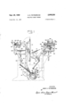
Figure 1 a schematic side elevational view of a printing press embodying the multi-sheet feeding mechanism.
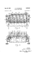
Figure 2 is an enlarged plan view of the feeding mechanism.
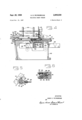
Figure 3 is a front elevation, partly in section, of Figure 2.
Figure 4 is a sectional view taken substantially on the line IV-IV of Figure 2.
Figure 5 is a sectional view of the releasable latch for connecting the feeder to the feeder arms.
Figure 6 is an enlarged sectional plan view of the sheet pusher assembly.
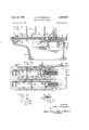
Figure 7 is a sectional view in elevation of a modification of the feeder.
Figure 8 is a fragmentary plan view of Figure 7.
Figure 9 is a sectional view taken along line IXIX of Figure 8; and
Figure 10, is a front elevational view of a rear pile guide.
My invention as herein described pertains to a device for continuously and simultaneously feeding a plurality of blanks such as checks, business machine cards, blotters, etc., to a printing press. It it designed, and particularly adapted for operation in conjunction with the standard feeding mechanism of a printing press known in the art as the Miehle Vertical press. Such press, is schematically illustrated in Figure 1 and includes a type bed 10 and an impression cylinder 11 which are mounted for simultaneous vertical reciprocation in opposite directions, the cylinder 11 being adapted to rotate counter-clockwise on its upward or printing stroke whereas it is locked against rotation on the downward or sheet receiving stroke. These members are actuated by means of links 12 which are pivotally connected to cranks '13 secured to the main drive shaft 14.
A feed table 16 normally supports a stack of sheets to be printed and individual sheets are separated from the top of such pile by pneumatic suckers 18 which are carried by oppositely arranged feeder arms 19 fixed on a rock shaft 21. The suckers 18 pick up the sheets on the feed table 16 and deposit them on a register table 17 which is adapted to move up and down with the cylinder 11 and is provided with means for registering the sheets and transfering them to the cylinder grippers 22.
The arms 19 and therewith the pneumatic suckers 18 are oscillated in timed relation to the movements of the cylinder 11 by means of a continuously rotating cam 23 which is secured to a driven cam shaft 24. A lever 25 is secured to the rock shaft 21 and has connected thereto one end of a link 26 the other end of which is connected to one arm of a bell crank 27 which is pivotally mounted as at 28. The other arm of said bell crank carries a laterally extending roller 29 which moves in the cam race 30 of the cam 23. Thus it will be seen that as the cam 23 rotates, the cam race 30 transmits a positive oscillating motion to the feeder arms 19 for conveying sheets from the feed table 16 to the register table 17.
After the sheets have received an impression on the cylinder 11 and said cylinder has moved to the top position of its reciprocating cycle, the sheets are gripped by delivery grippers 31 and conveyed to a delivery table 32. The delivery grippers are carried by oppositely arranged arms 33 which are mounted on a rock shaft 34 and are adapted to be oscillated in timed relation to the movements of cylinder 11. The arms 33 also are driven from the cam shaft 24 through a crank shaft 36 which is mounted to rotate with said shaft and has pivotally connected thereto one end of a connecting link 37. The other end of the link 37 is connected to a lever 38 secured to the rock shaft 34. Therefore, as shaft 24 engage the top edge of the cross bar 51. By adjusting the screw 58 the front guides 48 can be raised and lowered relative to the top surface of plate 41 for calipering the blanks as will be explained more fully hereinafter.
From the description thus far, it will be apparent that the blanks to be printed will be arranged in stacks and one such stack will be positioned over each slot 42 between the standards 49 on the side guides 43 and between the rear guides 45 and the front guides 48. Thus it will be seen that as successive sheets are withdrawn from the bottom of each stack, additional blanks can be inserted from above without interrupting the operation of the press.
Furthermore, as the blanks settle progressively towardthe surface of plate 41 as preceding blanks are withdrawn, the inclined walls 44 of the side guides 43 effectively center each blank with respect to the slots 42. In a similar manner the inclined walls 47 of the rear guides 45 urge the bottom blanks against the front guides 48 so they will feed table 16 and which device will present a plurality of small size blanks simultaneously to the suckers 18. The auxiliary feeding device essentially comprises a substantially rectangular frame 40 on the top of which is mounted a fiat plate 41. The frame member 40 is adapted to be bolted, clamped or otherwise releasably secured to the feed table 16 so that it occupies the space normally taken up by a stack of sheets when the press is operated in the conventional manner. It will be understood that when the auxiliary feeder is used, the mechanism for automatically elevating the feed table 16 will be disengaged and that the table will be adjusted so that the top surface of the plate 41 will be at an operative position with respect to the pneumatic suckers 18.
As shown in Figure 2 the plate 41 is provided with a series of parallel slots 42 arranged in spaced relation transversely of said plate and through which sheet ad vancing members project to engage the bottom blanks in each stack, as will be explained more fully hereinafter. Secured to the top plate 41 on each side of the slots 42, are side guides 43 which are somewhat prismatic in cross section having inclined side walls 44. Rear guides 45 are secured to the ends of the side guides 43 by means of bolts 46 and have inclined front walls 47. The side guides 43 also are provided with spaced vertical standards 49.
Adjacent the front edges of the side guides 43 are a series of front guides 48. One of these front guides is positioned over each slot 42 intermediate the side guides 43 and they are supported by means of a cross bar 51 which extends across the full width of the plate 41,-said bar being fastened by means of bolts 52 to L shaped brackets 53 which in turn are bolted to the top surface of the respective side guides 43. The cross bar 51 is spaced above the plate 41 and is provided with a series of spaced vertical grooves in which the front guides 48 are positioned. Socket head screws 54 secure the front guides to the cross bar 51, said screws being inserted through vertical slots 56 in the cross bar 51 and threaded into the front guide members 48.
Each front guide 48 also is provided with a boss 57, Figure 4, which is drilled and tapped to receive an adjusting screw 58, the depending end of which is adapted to means of a toggle link 67 to the guide rail 63.
be in position for engagement by the blank feeding elements. Consequently, there is no need for complicated and expensive side and rear jogger mechanism for this purpose.
Mounted for reciprocatory motion below the plate 41 is a carriage member 59 which extends transversely of the frame 40 and is provided at each end with bosses 61, see Figure 3. These bosses project through openings 62 provided in the walls of the frame member 40 and carry at their free ends the horizontally disposed guide rails 63. The guide rails in turn are supported between coacting rollers 64 which are rotatably mounted on the side walls of the frame 40 above and below the openings 62 and in a manner that their peripheries engage the top and bottom edges of the guide rails 63.
Pivotally mounted on each side of the frame member 40 is a lever 66 the upper end of which is connected by The lower end of said lever in turn is connected to the oscillating feeder arms 19, by means of the connecting rod 68. Thus it will be seen that as the feeder arms oscillate, a corresponding motion will be imparted to the carriage member 59 through the connecting linkage and which motion will be in opposed relation to that of the arms 19.
As is shown more clearly in Figure 5, the connecting rod 68 is connected to the feeder arm 19 by a quick release latch mechanism to facilitate installation and removal of the auxiliary feed device. This mechanism comprises a fitting 69 which is threaded onto the end of rod 68 and is formed with a transverse slot 71 having inclined side walls 72. The feeder arms 19 in turn are formed with a boss 73 in which is pivotally mounted a laterally projecting pin 74, the walls of which are inclined to fit tightly in the slot 71.
The fitting 69 is locked in position on the pin 74 by means of the arcuate latch 76 which is pivotally mounted on a pin 77 between the projecting ears 78 on the upper side of the fitting 69. Latch 76 is formed at its lower end with a flat face 79 which is adapted, when in locking position, to engage the lower face of pin 74 to prevent the respective members from becoming disengaged. The
connection may quickly be released by turning the latch 76 clockwise and lifting the fitting 69 off of the pin 74. From the description thus far it will be apparent that the carriage member 59 is movably supported for reciprocating motion between the rollers 64 mounted on each side of the frame member 40 and that it is adapted to be driven in timed relation to the feeder arms 19 by mechanism connected directly to said arms.
In order that a bottom sheet of each stack will be advanced on the top plate 41 for each forward movement of the carriage member 59, said member is provided with a series of sheet pusher assemblies indicated generally at 80 in Figure 2. These assemblies are arranged in spaced relation transversely of the carriage and in a inanner that they coincide with the slots 42 in the top plate 41.
The sheet pusher assemblies preferably comprise a fixed base member 81 which is bolted securely to the top surface of the carriage 59, an adjustable supporting block 82, and a sheet pusher blade 83. As shown more clearly in Figure 6, the supporting block 82 is connected to the base member 81 by means of a bolt 84 which is inserted through an opening in the block 82 and threaded into the base member 81. By adjusting the bolt 84 the position of the with respect to the carriage 59. The compression spring 86 mounted over the bolt 84 exerts constant pressure against the block 82 to maintain it in contact with the head of bolt 84.
The sheet pusher blade 83 is in turn secured to the supporting block 82 by means of the bolts 87. These bolts extend through the block 82 and are provided with extensions 88 of reduced diameter and which are adapted to be slidably received in recesses 89 in the base 81 to prevent any angular movement of the block 82 about the axis of the bolt 84.
It will be understood that the pusher blade 83 is adjusted so that it projects above the top surface of plate 41 by an amount substantially equal to the thickness of the sheets being processed so that only the bottom sheet will be engaged and advanced for each forward stroke of the carriage 59. It also will be understood that the openings in the blade 83, through which the bolts 87 are inserted, are elongated vertically to permit such adjustments of the block.
Due to the movement of the carriage 59 in reverse relation to the feeder arms 19, the pusher blades 83 are in a position substantially under the center of the respective stacks, as shown in Figure 4, when the leading edge of the advanced sheet is engaged by the pneumatic suckers 18. Consequently, as the suckers 18 withdraw the bottom sheet, the pusher blades 83 tend to support the weight of the stacks thereby relieving the pressure on the bottom sheet and permitting it to be more freely Withdrawn.
Moreover, the simultaneous reverse movement of the pusher blades, as the sheet is withdrawn by the suckers 18, tends to counteract any tendency for the next succeeding sheet to move forward with the advanced sheet due to the friction between said sheets.
Sheet calipering means are also provided to further prevent the feeding of more than one sheet from each stack for each reciprocation of the carriage 59. As shown in Figure 4, a choke roller 91 is rotatably mounted below each front guide 48 in a supporting member 92 which in turn is secured in position in the respective slots 42 by means of clamps 93. The periphery of roller 91 is preferably tangent to the surface of plate 41 and the front guide 48 is adjusted vertically relative thereto so that there will be only enough space between its bottom edge and the periphery of the roller 91 to permit passage of one blank therethrough.
For each stroke of the carriage 59 each pusher blade 83 advances a blank on the surface of the plate 41 and projects it against the front guide 97 which is secured to the frame 40 in a manner that it projects above the top plate 41. At this point the blanks are engaged by the pneumatic suckers 18 which are adapted to initially raise the front portion of the blanks above the front guide 97 and then carry them in an arcuate path to the register table 17.
This action of the suckers 18 normally causes the blanks to bend about the bottom edge of the front guides 48, the relatively sharp edges of which create considerable drag on the blanks which in many instances causes the blank to be pulled away from the sucker 18. To relieve this condition, a round bar 96 is mounted immediately forward of the front guides 48 in spaced relation to the blade 83 can be advanced or retracted top plate 41 and which extends across the full width thereof. Consequently, as the blanks are raised by the suckers 18 they bend around the curved, smooth surface of the bar 96 which causes comparatively little friction or drag on the blank and they move substantially horizontally under the front guide 48.
In many instances it is desirable to be able to suspend feeding of the blanks after a predetermined number have been printed without stopping the press. This is especially true in the printing of blank checks for example, which are subsequently bound in lots of 25 or 50 as the case may be. In such case, each time a specified number of blanks have been printed, the operator removes the blanks from the press and repositions the delivery table to receive the next batch. This operation usually can be eifected within a minute or less but unless feeding of the blanks can be suspended momentarily, it becomes necessary to stop the press. Such intermittent starting and stopping is hard on the press drive mechanism and also adds to the operating cost.
In order to effectively suspend feeding of the blanks for such operations and without necessitating stopping of the press, means are provided for raising the rear edges of the stacks of blanks out of the paths of the reciprocating pusher fingers 83. These means comprise a shaft 98 which is rotatably mounted on the top plate 41 in brackets 99 and 101 adjacent the rear edges of the stacks of blanks. A series of arcuate fingers 102 are fixed securely to said shaft in spaced relation thereon and in a manner that they project into the respective slots 42 and under the rear edge of each stack of blanks.
Bracket 101 also supports a short shaft 103 which is provided at one end with manually operable lever 104 whereby the shaft 103 can be rotated. A11 eccentrtic collar 106 is secured to the opposite end of shaft 103 in a manner that it engages a rearwardly projecting lever 107 fixed on the shaft 98. Thus it will be seen that by turning shaft 103 the eccentric collar 106 depresses lever 107 thereby causing shaft 98 to rotate counterclockwise. Such motion brings the fingers 102 up under the blanks so as to raise the rear edges thereof out of the paths of the pusher fingers 83. Consequently, the press and feeder mechanism will continue operating, but no blanks will be fed through. To resume feeding of the sheets, lever 104 is returned to its original position thereby allowing the fingers 102 to rock clockwise and lower the blanks once again into the paths of the pusher fingers 83.
The delivery mechanism also is modified somewhat in order to facilitate the delivery of the sheets and to provide for their removal after a pre-determined number thereof have accumulated on the respective stacks. As shown in Figure 1, a bracket 121, which is releasably mounted on a standard 122, supports a plurality of vertical panels 123 which, in combination with the rear jogger fingers 124, define the receptacles into which the blanks are deposited.
Fixed to the rear jogger arms 125 at each side of the delivery mechanism are L shaped brackets 126. These brackets extend rearwardly and each one has fixed thereto a pair of vertically disposed flat springs 127. A horizontally disposed block 128 is fixed to the depending ends of the springs 127 which provides support for a delivery board 129. It will be appreciated that similar springs and a corresponding block is provided on each side of the press for supporting the delivery board 129 in a horizontal position. Therefore, as the sheets are delivered by the delivery grippers 31, they are deposited in their own individual receptacles on the delivery table 129 where they are allowed to accumulate until a predetermined number have been printed. To remove the delivery table 129 and therewith the stacks of sheets, the blocks 128 are spread outwardly or laterally against the tension of the flat springs 127 and until they clear the side edges of the delivery board which can then be lowered and removed with the stacks of sheets intact. Another delivery board 129 is then inserted in position on the blocks 128 and operation of the press can be continued immediately. It is for'this purpose that the tripping mechanism is provided so that feeding of the sheets can be suspended while the previously printed sheets are removed from the delivery mechanism and an empty delivery table is inserted in position to receive the sheets.
Figures 7 to 10 inclusive, illustrate a modified embodiment of the feeder incorporating adjustable features whereby blanks of various lengths can readily be processed.
In this embodiment the frame 40 and top plate 41 are extended longitudinally so that they can accommodate blanks of the maximum length that the press will handle. The length of the side guides 43 is also correspondingly increased and an additional standard 49 is provided so as to adequately support the maximum size blanks.
Rear guides 135 are arranged to extend crosswise between adjacent pairs of side guides 43 and the side edges of the rear guides are formed to fit into vertical slots 136 provided therefor in each of the side guides 43. As shown, four such slots are provided in each side guide so that the rear guides can be positioned to accommodate the four standard sizes of check blanks. Obviously, the rear guides can be made infinitely variable if the need for such adjustability should arise.
The sheet pusher fingers 83 also are adapted to be adjustable longitudinally of the direction of feed to compensate for different lengths of blanks. The fingers 83 are secured by means of bolts 137 to supporting block 138 which in turn is fixed to the end of a flat bar 139. The bar 139 is prismatic in cross section, having tapered sidewalls, as shown in Figure 9, and it is adapted to he slidably received in a correspondingly shaped groove 141 formed in the top surface of the carriage member 59. A slot 142 is formed in the bar 139 parallel with and midway between its side edges. A screw 143 is inserted through the slot 142 and threaded into the carriage member 59. When tightened, the screw 143 locks the bar 13 in its adjusted position.
The sheet tripping mechanism also is modified from that disclosed in Figures 2 and 4 in order to be effective for any length of sheet.
As shownin Figures 7 and 8 this mechanism comprises a lever 146 which is arranged horizontally along one edge of its respective slot 42. At its forward end the lever is pivotally mounted on a pin 147 while its rear or free end is adapted to rest on the periphery of an eccentric collar 148 fixed to a transverse shaft 149. A series of the eccentric collars 148 are arranged in spaced relation on the shaft 149, one for each slot 42, see Figure 8.
The shaft 149 is in turn journalled for rotation in the opposite side walls of the frame member 40, below the top plate 41 and a manual control lever 151 is provided at one end thereof for rotating the shaft.
When in normal operation, the eccentric collars 148 and associated levers 146 are in the positions illustrated by solid lines in Figure 7. To trip the blanks out of the paths of the pusher fingers, the shaft 149 is rotated through 180 thereby moving the eccentric collars and associated levers to the position indicated by the broken lines in Figure 7.
Thus it will be apparent that regardless of the number of stacks of blanks being processed or the length of the blanks in the different stacks, the forwarding of all sheets can be suspended merely by turning the single control 151 through 180".
In order to avoid interference with the pusher fingers 83 or the trip levers 146 the rear guides 135 are provided with notches 152 and 153 as shown in Fig. 10. The notch 153 being sufiiciently deep so as to clear lever 146 when the rear guide is positioned in the last slots 136 for a maximum size sheet.
While there have been shown and described the fundamental novel features of the invention as applied to a preferred embodiment, it will be understood that various modifications and changes in the form and details of the apparatus illustrated and its mode of operation may be made by those skilled in the art without departing from the spirit of the invention. It is the intention, therefore, to cover any such modifications and improvements as will come within the scope of the appended claims.
What I claim isi 1. A feeding mechanism comprising, a support for a stack of sheets, pneumatic means including continuously oscillating arms for engaging and forwardling sheets from said support, means for successively advancing the bottom sheet of said stack on said support for engagement by said pneumatic means including a reciprocable member arranged beneath said support, means interconnecting said member with said arms for reciprocating said member in opposed relation to said arms, and manually operable means mounted adjacent the rear edge of said support for raising the sheets in said stack whereby to suspend feeding thereof.
2. Mechanism for feeding sheets to the impression cylinder of a printing press comprising, a slotted plate for supporting a plurality of stacks of sheets, a carriage mounted for reciprocation beneath said plate, pusher means on said carriage adapted to project through the slots in said plate to engage the rear edge of the bottom sheet of each stack and advance the latter on said support upon reciprocation of said carriage, pneumatic means including oscillating arms for engaging the sheet thus advanced and conveying it to the impression cylinder, and drive means interconnecting said arms with said carriage in a manner whereby said carriage is reciprocated in directions opposite with respect to and in timed relation with said arms.
3. A feeding mechanism comprising, a feed table for supporting a plurality of stacks of sheets, pneumatic means including continuously oscillating arms for engaging and forwarding sheets from said table, means for successively advancing the bottom sheets of each stack simultaneously on said table for engagement by said pneumatic means including a reciprocable member arranged beneath said table, a series of sheet pusher ele ments on said member adapted to engage the rear edge of and initially advance the bottom sheet of each stack for each reciprocation of said member, a rotatable shaft, a series of fingers fixed to said shaft with their free ends projecting beneath said stacks, and means for rocking said shaft and therewith said fingers to raise the rear edges of the sheets out of the paths of said elements to prevent feeding of the sheets.
4. Mechanism for feeding sheets to the impression cylinder of a printing press or the like machine comprising, a feed table for supporting a stack of sheets, mechanism including a reciprocable member for initially advancing the bottom sheet of said stack to an advanced position on said feed table, means including continuously oscillating arms for conveying the sheet from said advanced position to the impression cylinder, and means interconnected between said arms and said member for reciprocating the latter in opposite directions with respect to said arms.
5. Mechanism for feeding sheets to the impression cylinder of a printing press or the like machine comprising, a feed table for supporting a stack of sheets, a member mounted for reciprocation below said table for initially advancing the bottom sheet of said stack to an advanced position on said feed table, feed means including sheet gripper elements and oscillatable supporting arms mounted between the feed table and the impression cylinder for conveying the sheet from said advanced position to said cylinder, drive means for continuously oscillating said arms, and means interconnected between said arms and said member for reciprocating the latter in opposite directions with respect to said arms and in timed relation therewith.
6. Mechanism for feeding sheets to the impression cylinder of a printing press or the like machine comprising, a feed table for supporting a stack of sheets, means including continuously oscillating arms for conveying sheets from said table to the impression cylinder, a member mounted for reciprocation below said table for successively advancing the bottom sheet of said stack to an advanced position on said table for engagement by said means, and means for reciprocating said member in opposed relation to said arms including a lever pivotally mounted on said feed table, toggle means connecting one end of said lever to said member, and means interconnecting the other end of said lever with said arms.
References Cited in the file of this patent UNITED STATES PATENTS Chvojka July 27, Chatterton Feb. 20, Burkholder Mar. 18, Keen Dec. 8, Greenwood July 24, Tebbs Sept. 4, Gentry Dec. 24,
Priority Applications (1)
| Application Number | Priority Date | Filing Date | Title |
|---|---|---|---|
| US698004A US2906528A (en) | 1957-11-21 | 1957-11-21 | Multiple sheet feeder |
Applications Claiming Priority (1)
| Application Number | Priority Date | Filing Date | Title |
|---|---|---|---|
| US698004A US2906528A (en) | 1957-11-21 | 1957-11-21 | Multiple sheet feeder |
Publications (1)
| Publication Number | Publication Date |
|---|---|
| US2906528A true US2906528A (en) | 1959-09-29 |
Family
ID=24803512
Family Applications (1)
| Application Number | Title | Priority Date | Filing Date |
|---|---|---|---|
| US698004A Expired - Lifetime US2906528A (en) | 1957-11-21 | 1957-11-21 | Multiple sheet feeder |
Country Status (1)
| Country | Link |
|---|---|
| US (1) | US2906528A (en) |
Cited By (2)
| Publication number | Priority date | Publication date | Assignee | Title |
|---|---|---|---|---|
| EP0011073A1 (en) * | 1978-11-15 | 1980-05-28 | HATANAKA, Takefumi | Automatic document disintegrator |
| US8478619B2 (en) | 2000-12-29 | 2013-07-02 | Arrowstream, Inc. | Transport vehicle capacity maximization logistics system and method of same |
Citations (7)
| Publication number | Priority date | Publication date | Assignee | Title |
|---|---|---|---|---|
| US1593620A (en) * | 1923-03-10 | 1926-07-27 | William J Freihofer | Article-delivering device |
| US2541985A (en) * | 1946-12-19 | 1951-02-20 | American Can Co | Sheet separating and feeding mechanism |
| US2589600A (en) * | 1947-04-01 | 1952-03-18 | Gen Box Distributors | Feeding device for box-part assembling machines |
| US2661685A (en) * | 1949-04-14 | 1953-12-08 | Ibm | Card controlled printing machine |
| US2756113A (en) * | 1954-08-02 | 1956-07-24 | Henry B Greenwood | Adjustable bed slide for printing and slotting machines |
| US2761681A (en) * | 1952-07-09 | 1956-09-04 | Headley Townsend Backhouse | Sheet feeding apparatus |
| US2817520A (en) * | 1956-06-25 | 1957-12-24 | Atlanta Paper Company | Blank feeding means |
-
1957
- 1957-11-21 US US698004A patent/US2906528A/en not_active Expired - Lifetime
Patent Citations (7)
| Publication number | Priority date | Publication date | Assignee | Title |
|---|---|---|---|---|
| US1593620A (en) * | 1923-03-10 | 1926-07-27 | William J Freihofer | Article-delivering device |
| US2541985A (en) * | 1946-12-19 | 1951-02-20 | American Can Co | Sheet separating and feeding mechanism |
| US2589600A (en) * | 1947-04-01 | 1952-03-18 | Gen Box Distributors | Feeding device for box-part assembling machines |
| US2661685A (en) * | 1949-04-14 | 1953-12-08 | Ibm | Card controlled printing machine |
| US2761681A (en) * | 1952-07-09 | 1956-09-04 | Headley Townsend Backhouse | Sheet feeding apparatus |
| US2756113A (en) * | 1954-08-02 | 1956-07-24 | Henry B Greenwood | Adjustable bed slide for printing and slotting machines |
| US2817520A (en) * | 1956-06-25 | 1957-12-24 | Atlanta Paper Company | Blank feeding means |
Cited By (2)
| Publication number | Priority date | Publication date | Assignee | Title |
|---|---|---|---|---|
| EP0011073A1 (en) * | 1978-11-15 | 1980-05-28 | HATANAKA, Takefumi | Automatic document disintegrator |
| US8478619B2 (en) | 2000-12-29 | 2013-07-02 | Arrowstream, Inc. | Transport vehicle capacity maximization logistics system and method of same |
Similar Documents
| Publication | Publication Date | Title |
|---|---|---|
| US3773319A (en) | Corrugated sheet inverting machine | |
| US3120180A (en) | Screen stencilling machine | |
| CN215397234U (en) | Paperboard positioning device for box gluing machine | |
| US2906528A (en) | Multiple sheet feeder | |
| US3713651A (en) | Jogger assembly for carton blank stacker | |
| CN208843424U (en) | A kind of stacking paper feeding mechanism | |
| US2113650A (en) | Sheet delivery device | |
| US20120128461A1 (en) | Stacking device for groups of disposable wipes | |
| US2642282A (en) | Mechanism for feeding sheets to rotary drum machines | |
| US3861516A (en) | Apparatus for feeding sheets of paper or the like into a punching machine in neat stacks | |
| US2906529A (en) | Feeder for carton and the like material | |
| US3102632A (en) | Edge piercing means and blank conveying means | |
| US1811618A (en) | Delivery mechanism | |
| US2870703A (en) | Screen printing machines | |
| US1988970A (en) | Lithographing press | |
| CN211225607U (en) | A align and carry pan feeding structure for continuous printing machine | |
| CN204603112U (en) | A kind of reversible positioning and feeding device | |
| JPH0725460B2 (en) | Sheet ejection device for printing machines | |
| US3074710A (en) | Tabloid folding machine | |
| CN209740345U (en) | Blanking conveying device of hob transverse cutting machine | |
| US3699831A (en) | Cutter and creaser | |
| US2040686A (en) | Planetary printing press | |
| KR20130136273A (en) | Automatic sheet feeder for thomson cutter | |
| US3881720A (en) | Gripless sheet guiding apparatus | |
| CN213170712U (en) | Printing stock feeding mechanism of screen process press |