US288317A - palmee - Google Patents
palmee Download PDFInfo
- Publication number
- US288317A US288317A US288317DA US288317A US 288317 A US288317 A US 288317A US 288317D A US288317D A US 288317DA US 288317 A US288317 A US 288317A
- Authority
- US
- United States
- Prior art keywords
- seed
- slide
- wheels
- palmer
- axle
- Prior art date
- Legal status (The legal status is an assumption and is not a legal conclusion. Google has not performed a legal analysis and makes no representation as to the accuracy of the status listed.)
- Expired - Lifetime
Links
- 206010012289 Dementia Diseases 0.000 description 2
- 241000196324 Embryophyta Species 0.000 description 2
- 240000008042 Zea mays Species 0.000 description 2
- 235000005824 Zea mays ssp. parviglumis Nutrition 0.000 description 2
- 235000002017 Zea mays subsp mays Nutrition 0.000 description 2
- 238000010276 construction Methods 0.000 description 2
- 235000005822 corn Nutrition 0.000 description 2
- 241000507564 Aplanes Species 0.000 description 1
- 240000001931 Ludwigia octovalvis Species 0.000 description 1
- 230000035939 shock Effects 0.000 description 1
Images
Classifications
-
- A—HUMAN NECESSITIES
- A01—AGRICULTURE; FORESTRY; ANIMAL HUSBANDRY; HUNTING; TRAPPING; FISHING
- A01C—PLANTING; SOWING; FERTILISING
- A01C7/00—Sowing
- A01C7/18—Machines for depositing quantities of seed at intervals
Definitions
- This invention relates-to an improvement in seed-droppers; and it consists in certain peculiarities of construction whereby the seed-slide is noperated by a spring-arm adapted to give ⁇ way and prevent breakage, should the slide become clogged, substantially as will be hereinafter more fully set forth.
- A represents the main frame of the machine
- each seed-bozeA2 To the rear side of each seed-bozeA2 is secured a vertically-slotted frame, B, through which passes the axle B', having the wheels B2 upon each end and free to rise and fall in the slotted frames, as will be readily seen by ⁇ reference to Fig. 2.
- v Inthe upper ends of the frames B is also j journaled a rock-shaft, C, provided with two pulleys or enlargements, c o, to which issel cured a band, C, looped around the axle B',
- the wheels BZ are formed ⁇ of any desired size, and are provided on their peripheries with projections or points b, which catch in the ground and form means for enabling the wheels to drive the seed-slide.
- Each wheel is also provided on its periphery with twoor y j more ⁇ flat paddles or markers, b', which mark ,A Beit known that we, SAMUELDEMENT, SAM- ⁇ ⁇ UEI. D. PALMER, and JQHN A. PALMER, citi- ⁇ in the ground the exact llocation of each hill spendV and place the Vhills. in straight rows, as is usually done.
- small clips opposite each marker ⁇ b is also an adjustable dropping-arm, B3, the use of which will be presently described.
- brackets d d secured to the rear side of the frames B, are j ournaled two upright shafts, ,D D, each of which is provided, near its upper ⁇ ⁇ end and'above the seed-box and slotted frame,
- ⁇ of corn in order thatwhenone row has been l ,planted the others may be dropped to corre ⁇ Secured to the spokes by with a horizontalarm, D', projecting forward and having its other end connected by a link or pitman, d, with the upper end of a lever, E, which latter is fulcrumed in a crossbar of the main frame, and are connected at their lower ends to the seed-slide, as shown.
- a small stud, d2 upon which is arranged a sleeve, I, .rendered adjustable by means of a set-screw, lWand carrying a spring-arm, I', which curves around and rests against the upper end of the shaft D, and having its end proj ecting beyond, where it will contact with the arms B3 upon the wheel.
- the main frame pro- .vided With vertical slots, through which passes ⁇ a driving-axle, in combination with a rockvshaft having straps or chains looped round the axle B, carrying the driving-Wheels B2, in combination with'the rock-shaft C, havngnpulleys c c and bands C C, secured to said pulleys and looped around the axle, andthe lever C2, with its hook c all constructed and arranged to operate substantially as and for the purpose s et forth.
- the frame A having the main driving-axle B, adapted to move in vertical slots and carrying the Wheels B2, having adjustable dropping-arms B3, points b, and row-marking blades b, and the rock-shaft C, with its bands C and lever G2, adapted to lift the axle, vin combination with the shafts D D, arms D D', carryingI the adjustable sleeves I I, with the springs I I', pitmen d cl, levers E, fulcrumed in the main frame and secured at their lower ends to the dropping-slide, all constructed and arranged to operate substantiallyas and for the purpose set forth.
- SAMUEL DEMENT SAMUEL D. PALMER'. JOHN A. PALMER. Vitnesses:
Landscapes
- Life Sciences & Earth Sciences (AREA)
- Soil Sciences (AREA)
- Environmental Sciences (AREA)
- Breeding Of Plants And Reproduction By Means Of Culturing (AREA)
Description
(NoV Model.) 2 Sheets-Sheet 1.
S. DElVIEAN'Tl 8v S. D. & J. A. PALMER.
SEED DROPPER. l No. 233,317`
Patented Nov. 13. 1883.
N. PETERa Phnlumugnpher. wxshinglon. 4D. C
(No Model.) 2 SheetsZ--Sheef 2. S. DEMENT & S. D. &`J. A'. PALMER.
SEED DROPPER.
No. 288,317. Patented Nov. 13, 1883.
x n "I n.
N PETERS. PtwxmLilhogmphnr. wuhlngmm D. C.
. y UNITED STATES 4PATEIN'fr sAMIIEL DEMENT, sAMUELD. PALMER, AND .IoHN A. PALMER, oEEAsr LYNN;` ILLINoIs.
sEED-,DROPPER SPLCIFICATION farming part `of Letters Patent` No. 288,317, dated November 13, 1883.
` Application lerlMay8,1883. (No model.)
To aZZ whom it may concern.-
zens of the United States, residing at East Lynn,- in the county of Vermillion and State,
of Illinois, have invented certain new and useful Improvements in Seed-Droppers, of which the following is a specification, to wit:
This inventionrelates-to an improvement in seed-droppers; and it consists in certain peculiarities of construction whereby the seed-slide is noperated by a spring-arm adapted to give` way and prevent breakage, should the slide become clogged, substantially as will be hereinafter more fully set forth.
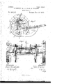
In order to enable others skilled in the art to which our invention lappertains to make and use the same, we will now proceed to del scribe its construction and operation, referring to the accompanying drawings, inwhich* Figurel is aplan view, Fig. 2 a longitudinal vertical section, and Fig. 3 a rear elevation,
of our invention.` i
A represents the main frame of the machine,
provided with the usual tongue, A', seedb`oxes A2, and openers or runners A3, as shown.
To the rear side of each seed-bozeA2 is secured a vertically-slotted frame, B, through which passes the axle B', having the wheels B2 upon each end and free to rise and fall in the slotted frames, as will be readily seen by` reference to Fig. 2. v Inthe upper ends of the frames B is also j journaled a rock-shaft, C, provided with two pulleys or enlargements, c o, to which issel cured a band, C, looped around the axle B',
` ,jin Fig. 2. `45
The wheels BZ are formed` of any desired size, and are provided on their peripheries with projections or points b, which catch in the ground and form means for enabling the wheels to drive the seed-slide. Each wheel is also provided on its periphery with twoor y j more `flat paddles or markers, b', which mark ,A Beit known that we, SAMUELDEMENT, SAM-` `UEI. D. PALMER, and JQHN A. PALMER, citi-` in the ground the exact llocation of each hill spendV and place the Vhills. in straight rows, as is usually done. small clips opposite each marker` b is also an adjustable dropping-arm, B3, the use of which will be presently described.
In brackets d d, secured to the rear side of the frames B, are j ournaled two upright shafts, ,D D, each of which is provided, near its upper` `end and'above the seed-box and slotted frame,
`of corn, in order thatwhenone row has been l ,planted the others may be dropped to corre` Secured to the spokes by with a horizontalarm, D', projecting forward and having its other end connected by a link or pitman, d, with the upper end of a lever, E, which latter is fulcrumed in a crossbar of the main frame, and are connected at their lower ends to the seed-slide, as shown.
From the upper side of the armD' projects a small stud, d2, upon which is arranged a sleeve, I, .rendered adjustable by means of a set-screw, lWand carrying a spring-arm, I', which curves around and rests against the upper end of the shaft D, and having its end proj ecting beyond, where it will contact with the arms B3 upon the wheel. j
In operation the wheels arelowered till their points and markers enter the ground, and when the machine is started one of the dropping-arms upon one of them strikesthe spring I and carries it forward, turning the armv D",
and, by its connections, carrying the dropping slide to plant two hills of corn or other seed 85.
\ the opposite wheelstrikes the adjacent springarm and moves the slide in the opposite direction, making another drop and marking the hill, as before. This operation is repeated,1
and upon turning at the end of the row to plant a new one,if the marking-points be gaged by the marks already made, the rows will be always straight and the hills the same distance apart. i
By the use of the spring-arm I to move the slide we avoid all unnecessary jars and shocks when the dropping-arms strike them, and the slide is started slowly andeasily, while if any IOO serious clogging or binding of the slide should` occur the spring-arm gives Way and prevents breakage or undue strain upon any part of the mechanism.
In passing from place to place the axle and Wheels are lifted and held up by the lever and Work-shaft, and most of the Weight is then borne by the runners or openers, as Will readily be understood.
Having thus fully. described our invention, what We claim as new, anddesire to secure by Letters Patent, is-'- 1. The combination, in a seed-planter, ofthe driving-Wheels provided with adjustable arms,
with a spring adapted by intermediate mechanism to operate the dropping-slide when moved by the driving-Wheels, substantially as and for the purpose set forth.
2. vIn a seed-dropper, the main frame pro- .vided With vertical slots, through which passes` a driving-axle, in combination with a rockvshaft having straps or chains looped round the axle B, carrying the driving-Wheels B2, in combination with'the rock-shaft C, havngnpulleys c c and bands C C, secured to said pulleys and looped around the axle, andthe lever C2, with its hook c all constructed and arranged to operate substantially as and for the purpose s et forth.
4. In a seed-planter, the frame A, having the main driving-axle B, adapted to move in vertical slots and carrying the Wheels B2, having adjustable dropping-arms B3, points b, and row-marking blades b, and the rock-shaft C, with its bands C and lever G2, adapted to lift the axle, vin combination with the shafts D D, arms D D', carryingI the adjustable sleeves I I, with the springs I I', pitmen d cl, levers E, fulcrumed in the main frame and secured at their lower ends to the dropping-slide, all constructed and arranged to operate substantiallyas and for the purpose set forth.
In testimony whereof We affix our signatures in presence of two witnesses.
SAMUEL DEMENT. SAMUEL D. PALMER'. JOHN A. PALMER. Vitnesses:
A. C. BARTON, JOHN BEAGLE.
Publications (1)
| Publication Number | Publication Date |
|---|---|
| US288317A true US288317A (en) | 1883-11-13 |
Family
ID=2357510
Family Applications (1)
| Application Number | Title | Priority Date | Filing Date |
|---|---|---|---|
| US288317D Expired - Lifetime US288317A (en) | palmee |
Country Status (1)
| Country | Link |
|---|---|
| US (1) | US288317A (en) |
-
0
- US US288317D patent/US288317A/en not_active Expired - Lifetime
Similar Documents
| Publication | Publication Date | Title |
|---|---|---|
| US288317A (en) | palmee | |
| US174013A (en) | Improvement in combined seed-planters and cultivators | |
| US827857A (en) | Automatic check-row corn planter and marker. | |
| US201479A (en) | Improvement in check-row-planter attachments | |
| US276388A (en) | Seed-planter | |
| US216127A (en) | Improvement in corn-planters | |
| US214227A (en) | Improvement in seed-planters | |
| US774101A (en) | Cotton-seed planter. | |
| US430451A (en) | Corn-planter | |
| US213788A (en) | Improvement in corn dropper and marker | |
| US312783A (en) | Check-rowing attachment for corn-planters | |
| US207250A (en) | Improvement in corn-planter and check-row marker | |
| US271676A (en) | Check-row corn-planter | |
| US179723A (en) | Improvement in seed-planters | |
| US600711A (en) | Check-row attachment for planters | |
| US286557A (en) | Corn-planter | |
| US169865A (en) | Improvement in check-rowers | |
| US138259A (en) | Improvement in corn-planters | |
| US493063A (en) | Combined planter and cultivator | |
| US267899A (en) | Potato planter | |
| US927607A (en) | Corn-planter. | |
| US182630A (en) | Improveivient in corn-planters | |
| US212959A (en) | Improvement in corn-planters | |
| US313296A (en) | Joseph bollilfgbb | |
| US1267006A (en) | Check-row attachment for corn-planters. |