US2881130A - Fluid coking of heavy hydrocarbons - Google Patents
Fluid coking of heavy hydrocarbons Download PDFInfo
- Publication number
- US2881130A US2881130A US375088A US37508853A US2881130A US 2881130 A US2881130 A US 2881130A US 375088 A US375088 A US 375088A US 37508853 A US37508853 A US 37508853A US 2881130 A US2881130 A US 2881130A
- Authority
- US
- United States
- Prior art keywords
- vessel
- coke
- coking
- oil
- solids
- Prior art date
- Legal status (The legal status is an assumption and is not a legal conclusion. Google has not performed a legal analysis and makes no representation as to the accuracy of the status listed.)
- Expired - Lifetime
Links
Images


Classifications
-
- C—CHEMISTRY; METALLURGY
- C10—PETROLEUM, GAS OR COKE INDUSTRIES; TECHNICAL GASES CONTAINING CARBON MONOXIDE; FUELS; LUBRICANTS; PEAT
- C10G—CRACKING HYDROCARBON OILS; PRODUCTION OF LIQUID HYDROCARBON MIXTURES, e.g. BY DESTRUCTIVE HYDROGENATION, OLIGOMERISATION, POLYMERISATION; RECOVERY OF HYDROCARBON OILS FROM OIL-SHALE, OIL-SAND, OR GASES; REFINING MIXTURES MAINLY CONSISTING OF HYDROCARBONS; REFORMING OF NAPHTHA; MINERAL WAXES
- C10G9/00—Thermal non-catalytic cracking, in the absence of hydrogen, of hydrocarbon oils
- C10G9/28—Thermal non-catalytic cracking, in the absence of hydrogen, of hydrocarbon oils with preheated moving solid material
- C10G9/32—Thermal non-catalytic cracking, in the absence of hydrogen, of hydrocarbon oils with preheated moving solid material according to the "fluidised-bed" technique
Definitions
- This invention relates to coking of heavy petroleum residiums in contact with hot fluidized solids and to an apparatus particularly adapted for such coking.
- Another serious problem is the building up of coke deposits in the vapor space above the bed and in the line carrying the vapor effluent. Another problem is the need to use relatively large amounts of extraneous fluidizing gas which dilutes the vapors leaving the vessel and increases the size and complexity of the subsequent fractionating and separating equipment.
- Another problem is to produce a gas oil suitable for catalytic cracking which is free of the metallic impurities such as nickel and vanadium which has a poisoning effect on the cracking catalyst.
- Another difficulty is proper control of the size of the particles. As the coke is formed on the particles of solid they continue to grow so that unless some means are provided to supply fine particles, the particles become bigger and bigger and will reach a point where the patricles cannot be properly fluidized or circulated through the burner.
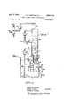
- Fig. 1 is a simplified showing of the apparatus forming a part of the present invention and in which the process may be carried out;
- Fig. 2 is an enlarged view of the upper separating and fractionating section of the coking vessel showing parts in section;
- Fig. 3 is an enlarged detail of the feed injection nozzle
- Fig. 4 illustrates a modification
- liquid feed passes into the coking system through line 1.
- Feeds suitable for the present invention are heavy or reduced crudes or vacuum bottoms or other heavy hydrocarbons containing a substantial amount of constituents which cannot be vaporized without decomposition.
- feeds may have an API gravity of about 0 to 20, e.g., 1.9", and a Conradson carbon content of about 5 to 40 weight percent, e.g., 30%.
- This feed is preferably preheated by conventional means to about 400 to 750 F., e.g., 700 F., so as to keep its viscosity reasonably low and to reduce the heat load on: the coking unit.
- From feed line 1 the liquid feed may be introduced into the dense turbulent fluidized coke bed 2 located in coking vessel 3.
- the feed is preferably injected into the bed at a multiplicity of points both circumferentially and vertically. As shown the feed passes through a manifold line 4 hav-v ing branch lines 5 communicating with nozzles 6 (see Figure 3).
- nozzle Any type of nozzle which will obtain a fine dispersion of the feed without requiring excessive amounts of dispersion gas may be used.
- One particularly good nozzle for this service is the jet type illustrated in Figure 3 in which feed is fed into the nozzle in admixture with dispersion steam through a central conduit having a port 8. The conduit is surrounded by an annular passage 9 through which purging steam is passed to keep this zone free of coke and permit removal of the nozzle.
- the steam oil mixture at the nozzle tip may comprise from 25 to volume percent steam. It is generally possible to feed between 350-450 barrels of oil per nozzle per day.
- These nozzles are preferably of retractable type which permits the core to be removed and cleaned if they become The coke particles within the bed are maintainedin.
- gases and vapors rising upwardly therethrough will include fluidizing and stripping gas and vapors and gases formed by coking of the feed.
- the average superficial velocity of the rising gases is preferably maintained between .5 and 5 feet per second and preferably between 1 and 3 feet per second depending upon the size of the particles making up the bed. Higher velocities will increase turbulence but will reduce bed density.
- the individual particles making up the bed tend to grow as the operation proceeds and it is necessary to maintain control over the size of the particles. It is preferred to operate with solids having an average particle size ranging between 75 and 500 microns in diameter with a preferred average particle size range between 150 and 300 microns. Preferably not more than 5% has a particle size above 500 microns while particles smaller than 40 microns tend to agglomerate or are swept out of the system with the gases. It is usually desirable to have from 5 to 20% of particles between 40 and 125 microns to improve fluidization and to scour the intermediate portion of the equipment as later described. While smaller particles provide more surface area, extremely fine particle are subject to agglomeration and other difficulties.
- the coking zone is maintained at the desired coking temperature by circulation of solids through a heater as later described.
- the coking temperature may range from 850 to 1200" F. and preferably between 900 and 1100 F. Higher temperatures permit greater feed rates and increase capacity but may tend to cause overcracking of the vapors with resultant lowering of yield of desired distillate products.
- the coking operation is usually carried out at relatively low pressure, such as from to 50 pounds per square inch gauge. While the process may be operated under subatmospheric pressure, it is generally preferred to operate at a vapor outlet pressure suflicient to force the vapors through subsequent fractionating and separating equipment. To this end the outlet pressure may be between and 25 pounds per square inch gauge and usually between 5 and 15 pounds. The pressure in the lower portion of the vessel will be somewhat higher due to the hydrostatic head developed by the fluidized bed.
- the lower portion of the coking bed below the point of feed injection serves as a stripping zone.
- Steam or other'stripping gas is injected into this zone through line 11 to displace hydrocarbon vaporsfrom the coke before removal of the latter from the coking zone.
- the stripper velocity may be between 0.3 and 5 ft. per second.
- the stripping steam may be injected into the vessel through nozzles at high velocity to cause attrition or grinding of the larger particles to maintain the desired particle size. To this end the gas may be injected at jet velocities of about 200-3000 ft. per second.
- The-total amount of steam injected into the coking and strippingzones mayequal about5 to 3 0 weightpercent of liquid hydrocarbon feed, 6 to 15 percent being the normal range.
- disc and doughnut baffles may be located in the stripping zone to improve contact between the steam and solids.
- the liquid bydrocarbon feed is injected into the reactorvthrough nozzles -6 at various levels and is-evenly deposited on the cokeparticles constituting the dense turbulent fluidbed.
- The-hydrocarbon feedrate maybeabout 0,1 tofl3 weight ,4 per hour per weight of solids present in the fluid bed depending upon the composition of the feed, coking temperature, residence time of.- solids in the bed and other factors.
- the limiting factor is the ability to maintain the bed in a highly turbulent fluidized state.
- the feed In the fluid bed the feed is converted to solid coke and hot hydrocarbon vapor.
- the vapors leaving the bed carry entrained solids. To permit some of these solids to settle out of the vapors, it is usually best to maintain the bed level 12 a substantial distance below the top of the vessel. It is desirable to have a certain minimum amount of entrained solids in the disengaging space 13 above the level of the bed.
- the heat contained in the entrained solids will help to maintain temperature in this zone at a higher level and prevent condensation and coking of higher boiling vapor products.
- the entrained solids will serve to scour the walls of the vessel of any coke which tends to deposit. It is also desirable to minimize the residence time of the vapors .in this zone to prevent further thermal cracking.
- the cross section of vessel 10 above the fluid bed level 12 may be reduced so as to increase the velocity of the rising vapors in the disengaging zone 13.
- This increased velocity entrains more coke, reduces vapor residence time, and keeps the reactor walls hotter and so minimizes condensation and coking as well as thermal cracking.
- the velocity of the gases in the disengaging zone maybe between 2 and 5 feet per second depending on particle size and other factors.
- additional hot coke may be introduced into the disengaging space as later described.
- the vapors pass from the top ofthe disengaging zone into dust separating devices such'as cyclones 14 which serve to separate entrained coke particles from the vapors.
- the separated fines are returned to the bed through dip legs 15.
- Aeration gas may be injected into the dip legs 15 through line 16 (see Figure 2).
- the amount of aeration gas so introduced may be controlled to regulate the amount of solids separated by the cyclones. For example in some cases it may be desirable to maintain a certain minimum of solids in the cyclone outlet to scour out any coke which may form. By increasing the amount of gas added to the dip legs, the amount of solids separated by the cyclones may be reduced.
- the cyclones themselves preferably are set in a solid transverse partition 16 which prevents vapors from reaching the stagnant zone above the cyclones and thus prevents coke from building up in this zone. From cyclones 14 the vapors pass through chimneys 17 into a scrubbing and fractionating tower 18 mounted directly above the coking vessel.
- the chimneys 17 preferably discharge the hot hydrocarbon-vapors against heated baffles 19.
- the bafiles 19 are positioned a substantial distance above the bottom of the scrubbing tower 18 and the spacebelow these baffles forms a collecting zone for heavy condensate formed in the scrubber. This prevents the heavy condensate from falling back into the chimneys and building upcoke deposits therein.
- baffles 18 and all other walls separating the coking vessel 3 from the scrubber tower 18 are preferably heavily insulated to minimize condensation and coking of the hydrocarbon vapors in the chimneys and bottom section-of the scrubbing tower.
- Heating elements preferably may be provided around the walls of chimneys 17 and the cyclone outlet lines to keep the walls-hotter than the vapors as afurther aid in preventing undesirable qqndenss q and q k e h heating e em t a be in the form pf superheated steam coils jacketingthe Walls as shown.
- This heating steam may be preheated by indirect heat exchange with hot solids in a later described coke burner and may be exhausted to the atmosphere, so as not to further dilute the vapors passing to subsequent fractionating and condensing equipment.
- hot flue gas from the coke burner may be used instead of steam in the heating coils.
- superheated steam may be injected directly into the hot vapors to minimize coking.
- the temperature in the bottom of the tower 18 is controlled to condense the heaviest portions of the vapors which contain metallic impurities such as iron, nickel and vanadium compounds originally present in the feed and carried overhead with the vapors. It will contain any entrained solids carried through the cyclones.
- the temperature at the bottom of the tower 18 is controlled by introducing a stream of quench oil through line 21.
- condensate collected in the bottom of the tower may be removed through line 24, a portion passed through cooler 26 (see Figure 1) and returned to the tower above a series of disc and doughnut baffies 27.
- a portion of this recycle stream may be passed into the bottom of the tower through line 28 to further cool the products being withdrawn.
- the maximum temperature at the bottom of the tower should not exceed about 750 F. in order to prevent coking of this section of the equipment.
- the temperature necessary to condense the metallic impurities will depend on the nature and amount of such impurities present in the feed. For most feeds the final boiling point of the products leaving the bottom section will be between 950 and 1050 F. Since the products leaving the scrubbing tower are composed of a wide mixture of vapors and gas, the end point of the uncondensed vapors will be considerably above the temperature maintained in the tower.
- Vapors remaining uncondensed in the bottom scrubbing section of the tower pass upwardly through a series of bubble cap trays located in the top of the tower where they are subjected to fractionation to condense an additional fraction of the gas oil boiling range.
- the condensate formed in the upper section collects in a trapout tray 29 and is withdrawn as a side stream through line 31. A portion of this stream is pumped back to the lower section of the tower below the trap-out tray through line 32 as additional scrubbing and cooling medium and another portion may be pumped through cooler 33 introduced into the top of the tower to serve as reflux.
- the temperature at the top of tower 18 should be kept above the dew point of steam, i.e., at a temperature of at least 200 to 225 F. This prevents condensation of steam which, if allowed to occur, might cause emulsion and corrosion problems in the top of the tower.
- the temperature of the vapors leaving the top of the tower may be about 300 F.
- the heavy condensate fraction withdrawn from the bottom of the scrubbing tower 18, through line 24, and not recycled for quenching and scrubbing as before described may be pumped through line 34 back to the coking vessel 3.
- the gas oil withdrawn as a side stream through line 31 constitutes a final product of the process. This oil being a condensate relatively free of residual components and metallic impurities may be subjected to catalytic cracking to form high quality gasoline.
- Uncondensed vapors and gas are withdrawn from the top of tower 18 through line 36, and passed through. water cooled condenser 37 ( Figure 2) and then to a separating drum 38 in which the liquid distillate separates from uncondensed gas.
- the liquid will comprise the naphtha fraction together with water.
- the naphtha is withdrawn .from the separator through line 39.
- Condensed water may be withdrawn from drum 38 through line 41.
- Wet gas may be withdrawn through line 42 and may be rejected or further processed to recover desired products therefrornr
- the total vapors from the scrubbing zone may be passed directly without further fractionation to a catalytic cracking zone.
- a stream of solids is continuously removed from the coking vessel through standpipe 43 which connects with the vessel at a point spaced some distance above the bottom.
- the space in the coking vessel below this line serves as a well or trap for collecting any large lumps or agglomerates which might serve to plug the transfer lines.
- the agglomerates may be periodically withdrawn through conduit 50.
- the standpipe 43 may have a wire cage or basket 44' around its inlet to prevent coarse lumps or agglomerates from lodging in the standpipe and connecting lines and stopping flow.
- the standpipe 43 connects at its lower end with a vertically inclined conduit 45 which, in turn, connects with a vertical riser 46 having a section 47 projecting upwardly into the lower portion of the heating vessel 48 below the level of a bed of fluidized solids maintained therein.
- a vertical riser 46 having a section 47 projecting upwardly into the lower portion of the heating vessel 48 below the level of a bed of fluidized solids maintained therein.
- Additional carrier gas may be injected into the lower end of the riser pipe 46 through line 51 to control the density in this section of the equipment. If desired a part of the air for combustion may be injected into the riser.
- the main stream of air for combustion is introduced through line 52 into an auxiliary burner 53.
- Fuel for combustion is added to the auxiliary burner through line 54.
- the auxiliary burner is normally used for heating up the unit at the start of the operation. After the unit is heated to proper temperature, the fuel supply is discontinued and the heat for the operation is obtained by burning coke formed in the process. In some locations, however, it may be more economical to burn extraneous gas rather than coke. In such cases the coke in the burner vessel 48 may be heated by combustion gases from the auxiliary burner. Gases, either air or hot combustion gases, as the case may be, pass from the auxiliary burner 53 into the bottom of the main burner vessel 48.
- the outlet from the burner is provided with a hood 55 to prevent solids draining from the main burner into the combustion zone of the auxiliary burner.
- Gases entering the bottom of the burner pass upwardly through the body of the vessel at a velocity regulated to maintain a dense turbulent bed of solids 56 lower portion of the burner vessel.
- the coke particles are heated in the burner vessel 48 to a temperature substantially above that maintained in the coking vessel.
- the temperature of the burner vessel may be from 1000 F. to 1500 F., usually about 200 to 300 F. above coking temperature.
- the standpipe 57 connects at its base with a vertically inclined conduit 63 which in turn connects with a vertical riser 64 through valve 65.
- a carrier gas is introduced into Jriser 64 through valved line 64 to control the density in, the riser.
- the riser pipe 64 connects with the upper portion of the coking vessel 3 below the level of the bed. .A portion of these hot solids may be passed through line 66 into the inlet to the cyclones 13 and 14 as earlier described to supply heat and scour the walls.
- the circulation is accomplished by maintaining. the density in the riser pipes 47 and 64 lower than in the standpipes 43 and 57 and the connecting fluidized beds so that the head of pressure generated at the base of the standpipes serves as a driving force to circulate the solids.
- the rate of circulation may be controlled primarily by the slide valve 67 in riser 46 and secondarily by regulating the amount of gas entering riser 47 or 64 or both.
- the unit may be designed to take a maximum of about a 4 pound per square inch pressure drop through the slide valve 67'.
- the standpipe 57 is designed to normally maintain a level of solids from to feet below the level of solids in the burner so that variations in the standpipe level can compensate for pressure surges in the system.
- the rate of circulation of solids between the coking vessel and burner is controlled to supply the required heat for the process and will depend upon the difference in temperature between the vessels.
- the weight of hot solids introduced into the coking vessel may be between about 8 to 19 times the weight of the oil charged per unit time.
- the size of the coking vessel should be such as to give the oil distributed on the coke adequate time to be converted into vapors and coke so that the solids passing to the burner is substantially free of unvaporized oil.
- the residence time of the solids in the reactor may be from 3 to 10 minutes or more.
- the amount of coke formed in the process will be greater than that necessary to supply the heat for the process.
- This excess coke is preferably withdrawn from the bottom of the standpipes 43 or 57.
- drawal pipes 68 and 69 connecting with conduit 70 into which the coke discharges into a stream of carrier gas such as steam.
- the coke is carried through a conduit by means of a carrier gas such as stream to a quench zone 71.
- a quenching medium such as water is introduced into the tower.
- the quenching medium is vaporized by heat of the solids.
- the quenched solids discharge into a cyclone separator 71 where the solids separate from the carrier gas and vaporized quenching medium.
- the coke separated in the cyclone discharges into a standpipe 81.
- Air is injected into the standpipes at one or more points through lines 82, 83 and 84 to dry strip and aerate the product coke.
- Standpipe 81 is sufficiently long to develop adequate pressure for subsequent pneumatic conveying of the coke to the product storage.
- Flow of solids through this standpipe is regulated by slide valve 85.
- the coke discharges from the base of the standpipe 85 into carrier line 86 into which carrier gas is passed through line 87 for transporting the coke to storage.
- the individual particles making up the fluid bed in the coking vessel grow in size due to the deposition of coke.
- a part of the withdrawn coke may be ground and returned to the system coking vessel.
- the solids withdrawn from the coking vessel and before being discharged from the unit or passed to the burner may be treated to selectively remove the finer par-' ticles sothat only a selected coarser fraction. is passed tothe-burner or withdrawn from the process.
- a part or all of the solids withdrawn from coking vessel through standpipe 43 is passed through line 72 to the intermediate section of an enlarged elutriator vessel 73 where it is contacted with' a rising stream of elutriating gas introduced into the' vessel below the point of entry of the SOllClS through line 74.
- the velocity of the rising gas passing through the elutriating vessel 73 is controlled to carry overhead a selected finer fraction of the solids while permitting a coarser fraction to collect in the bottom of the vessel.
- the elutriating gas containing the entrained fines are removed from the top of the vessel through line 75 and are returned to the coking vessel preferably at a low point therein.
- the elutriating vessel may be provided with a lower settling section below the point of introduction of the elutriating gas. A small amount of aerating gas may be introduced into the bottom of the elutriator through line 76.
- the coarse fraction is withdrawn from the elutriator 73 through conduit 77.
- a part or all of the coarser fraction may be withdrawn as product coke through lines 78 and 70 or a part or all may be passed through line 79 for transfer to the burner.
- the elutriator serves to retain the finer particles in the system until they have, grown to the maximum desired size for removal.
- the elutriator may be located at other points in the system. It is generally preferred to elutriate the stream before passing to the burner so as to pass only the coarse fraction to the burner because the finer material burns more readily. By keeping the finer material out of the burner, the amount of external grinding or internal attrition can be minimized. By controlling the amount of attrition by the high velocity stripping jets and by elutriation, the amount of fines re? tained in the system to replace the coarser material withdrawn can be regulated to maintain the particles at the desired size in the system.
- Top straight side (disengaging zone), 9' dia. x 20' Wide diameter (below dense bed), ll dia. x 16' .6 Middle section cone, 4' dia. x 11 dia. x 34' Stripper section, 4' x 10' Amount of stripping and fluidizing steam added at a higher point, 4940 pounds per hour Pressure of steam entering low pressure fluidiziug nozzles, 90 p.s.i.g.
- Bottom temperature 700 F. Trap out tray for gas oil, temperature 500 F. Top temperature, 275 F. Pressure bottom, 10 p.s.i.g. Pressure top, 9.5 p.s.i.g. Temperature heavy condensate quench oil to bottom of tower, 500 F., quantity 2910 b./s./d. Amount of heavy condensate recycled to coker, 1290 b./s./d. Temp. of gas oil reflux to top of scrubbing zone,
- coking unit forming the present invention has been described and illustrated in simplified form, it will be understood that a complete commercial unit will include a considerable amount of adjunctive equipment such as pumps, valves, temperature, pressure and level indicators, recorders and controllers, accumulator tanks, aeration and pressure taps, emergency rundown lines, storage tanks, etc.
- adjunctive equipment such as pumps, valves, temperature, pressure and level indicators, recorders and controllers, accumulator tanks, aeration and pressure taps, emergency rundown lines, storage tanks, etc.
- a process for the conversion of heavy oil containing metallic impurities which deactivate cracking catalyst and are vaporizable at conversion temperatures to form a gas oil suitable for catalytic cracking and coke which comprises introducing said oil at a multiplicity of horizontal and vertical points into the intermediate section of an enlarged coking zone containing a body of subdivided coke particles, circulating a stream of coke particles from the lower portion of the coking vessel through an external heater wherein said particles are heated by direct heat exchange and back to said coking vessel to maintain said vessel at a temperature sufficient to convert said oil into vapors and coke, introducing a stripping gas into the bottom section of said vessel to remove vaporized oil from the coke passing to said heater, injecting stripping gas as jets ranging from 200 to 3000 feet per second so as to break up large particles into small ones, maintaining said oil within said coking vessel for a period suflicient to convert said oil into vapors and coke, and passing the stripping gas and vapors formed in the process upwardly through the vessel
Landscapes
- Chemical & Material Sciences (AREA)
- Oil, Petroleum & Natural Gas (AREA)
- Physics & Mathematics (AREA)
- Thermal Sciences (AREA)
- Engineering & Computer Science (AREA)
- Chemical Kinetics & Catalysis (AREA)
- General Chemical & Material Sciences (AREA)
- Organic Chemistry (AREA)
- Production Of Liquid Hydrocarbon Mixture For Refining Petroleum (AREA)
Description
R. w. PFEIFFER ETAL 30 FLUID coxmc OF HEAVY HYDROCARBONS April 7, 1959 Fil ed. Aug. 19, 1953 3 Sheets-Sheet 1 BURNER VESSEL QUENCH) COOLER 6 I 8 I 4 5 0 5 6 V l G 6 W 6 I MN 6 :6 A. a. N0 WN mn m a Tc BT W5 K 4 CE C KS 6 3 6 As RE OE I R 9 7 CS 9 V L 2 4 m .2 0 4 H x 1.... Hu X 1 v 2 PLUM-Q1 1/ .3 M| |l|- Jk v G a 2 Z w 5 5 3 M 1 w. Iv Wm W 43 I 49 FIGURE-I 68 6 Robert W Pfeiffer Daniel S. Borey Inventors Charles E. Jahmg By MAHorney April 7, 1959 R. w. PFEIFFER ET AL FLUID COKING OF HEAVY HYDROCARBONS 3 Sheets-Sheet 3 I- E a w m. a w E m 5 A U LG P, F m w mfm w w w W R H LE "n s VL/-\ 2 7/4 a u s s v W: 9 M- 4 x l R U .m m ,5 M 4 F R 6 9 w M 7 a H I COKING VESSEL Robert W Pfeiffer Daniel S. Borey Inventors Charles' E. Jahnig e r 2,881,130 lQg Patented Apr-' 1959' FLUID 'COKING F HEAVY HYDROCARBONS Robert W. Pfeilfer, Bronxville, N.Y., and Daniel S. Borey,
Crauford, and Charles E. Jahnig, Red Bank, N.J., assignors to Esso Research and Engineering Company, a corporation of Delaware Application August 19, 1953, Serial No. 375,088
4 Claims. (Cl. 208-127) This invention relates to coking of heavy petroleum residiums in contact with hot fluidized solids and to an apparatus particularly adapted for such coking.
The ever growing demand for high quality motor fuel makes it increasingly imperative to upgrade heavy petroleum residues into distillate stock, and notably into gas oil suitable for catalytic cracking into motor fuel of high quality. One method of producing gasoline from heavy residue commonly used for many years is to pass the oil through a heating coil where it is heated to incipient cracking temperature and transfer it into a coking drum where it is maintained until it is converted into vapors and coke. The operation is continued until the drum is substantially full of coke. Following this flow of hot oil into the drum is interrupted and after sufiicient coking is broken into lumps and removed. To make the operation continuous through the coil a bank of coking drums may be provided for each coil so that the oil can be transferred from one drum to another as required. This process is commonly called delayed coking. The cooling down of the coking drums and removal of the coke is a time consuming, laborious job.
More recently it has been proposed to coke these heavy residium oils by injecting them into a coking vessel containing a fluidized bed of hot finely divided solids and to supply the necessary heat by circulating a stream of such solid through an external heater and back to the coking vessel. This offers a great advantage over the delayed coking process in that the operation is continuous. However, so far no commercial coking unit of this type has been operated.
Development of this type of process has uncovered a number of problems. One particularly serious problem is the tendency of the bed to lose is fluidity or bog down. If this happens the Whole bed may solidify and it is then necessary to stop the operation, cool the coking vessel, break up the coke into lumps and remove it from the vessel just as in the delayed coking process.
Another serious problem is the building up of coke deposits in the vapor space above the bed and in the line carrying the vapor effluent. Another problem is the need to use relatively large amounts of extraneous fluidizing gas which dilutes the vapors leaving the vessel and increases the size and complexity of the subsequent fractionating and separating equipment.
Another problem is to produce a gas oil suitable for catalytic cracking which is free of the metallic impurities such as nickel and vanadium which has a poisoning effect on the cracking catalyst.
Another difficulty is proper control of the size of the particles. As the coke is formed on the particles of solid they continue to grow so that unless some means are provided to supply fine particles, the particles become bigger and bigger and will reach a point where the patricles cannot be properly fluidized or circulated through the burner.
It is the object of this invention to provide an improved fluid coking process and apparatus which successfully overcomes these and other problems. Other objects as well as the nature and advantages of the invention will appear more clearly from the subsequent description, especially when read with reference to the accompanying drawing in which:
Fig. 1 is a simplified showing of the apparatus forming a part of the present invention and in which the process may be carried out;
Fig. 2 is an enlarged view of the upper separating and fractionating section of the coking vessel showing parts in section;
Fig. 3 is an enlarged detail of the feed injection nozzle, and
Fig. 4 illustrates a modification.
Referring to Figure 1, liquid feed passes into the coking system through line 1. Feeds suitable for the present invention are heavy or reduced crudes or vacuum bottoms or other heavy hydrocarbons containing a substantial amount of constituents which cannot be vaporized without decomposition. Typically, such feeds may have an API gravity of about 0 to 20, e.g., 1.9", and a Conradson carbon content of about 5 to 40 weight percent, e.g., 30%. This feed is preferably preheated by conventional means to about 400 to 750 F., e.g., 700 F., so as to keep its viscosity reasonably low and to reduce the heat load on: the coking unit. From feed line 1 the liquid feed may be introduced into the dense turbulent fluidized coke bed 2 located in coking vessel 3. To avoid the possibility of the bed losing fluidity and bogging down, it is important that the feed be quickly and uniformly distributed over the individual particles of the bed. While the highly turbulent fluid nature of the bed causes rapid dispersion of the feed throughout the bed, it is best not to rely entirely on the turbulence of the bed to effect the feed dispersion. order to prevent wetting of the coke particles at the point of feed injection and thus incur the risk of bogging the bed, the feed is preferably injected into the bed at a multiplicity of points both circumferentially and vertically. As shown the feed passes through a manifold line 4 hav-v ing branch lines 5 communicating with nozzles 6 (see Figure 3). Any type of nozzle which will obtain a fine dispersion of the feed without requiring excessive amounts of dispersion gas may be used. One particularly good nozzle for this service is the jet type illustrated in Figure 3 in which feed is fed into the nozzle in admixture with dispersion steam through a central conduit having a port 8. The conduit is surrounded by an annular passage 9 through which purging steam is passed to keep this zone free of coke and permit removal of the nozzle. The steam oil mixture at the nozzle tip may comprise from 25 to volume percent steam. It is generally possible to feed between 350-450 barrels of oil per nozzle per day. These nozzles are preferably of retractable type which permits the core to be removed and cleaned if they become The coke particles within the bed are maintainedin.
a turbulent fluidized condition by the gases and vapors rising upwardly therethrough. These gases and vapors will include fluidizing and stripping gas and vapors and gases formed by coking of the feed. Gases rising in the:
lower portion of the bed meet additional gases formed in the upper portion so that the volume of gas continuously. increases as it passes upwardly through the bed. The gas velocity in the lower part of the bed must be ade quate to maintain fluidization and effect the desired strip-. ping. By flaring the walls outwardly in the zone of feed 3 injection, the increase in volume of gases resulting from vaporization is more or less compensated for by increase in vessel diameter so that the velocity of the gases are maintained more or less uniform throughout the depth of the bed although there may be some increase in velocity toward the top of the bed.
The average superficial velocity of the rising gases is preferably maintained between .5 and 5 feet per second and preferably between 1 and 3 feet per second depending upon the size of the particles making up the bed. Higher velocities will increase turbulence but will reduce bed density.
.As before mentioned the individual particles making up the bed tend to grow as the operation proceeds and it is necessary to maintain control over the size of the particles. It is preferred to operate with solids having an average particle size ranging between 75 and 500 microns in diameter with a preferred average particle size range between 150 and 300 microns. Preferably not more than 5% has a particle size above 500 microns while particles smaller than 40 microns tend to agglomerate or are swept out of the system with the gases. It is usually desirable to have from 5 to 20% of particles between 40 and 125 microns to improve fluidization and to scour the intermediate portion of the equipment as later described. While smaller particles provide more surface area, extremely fine particle are subject to agglomeration and other difficulties.
The coking zone is maintained at the desired coking temperature by circulation of solids through a heater as later described.
The coking temperature may range from 850 to 1200" F. and preferably between 900 and 1100 F. Higher temperatures permit greater feed rates and increase capacity but may tend to cause overcracking of the vapors with resultant lowering of yield of desired distillate products.
The coking operation is usually carried out at relatively low pressure, such as from to 50 pounds per square inch gauge. While the process may be operated under subatmospheric pressure, it is generally preferred to operate at a vapor outlet pressure suflicient to force the vapors through subsequent fractionating and separating equipment. To this end the outlet pressure may be between and 25 pounds per square inch gauge and usually between 5 and 15 pounds. The pressure in the lower portion of the vessel will be somewhat higher due to the hydrostatic head developed by the fluidized bed.
As before stated, the lower portion of the coking bed below the point of feed injection serves as a stripping zone. Steam or other'stripping gas is injected into this zone through line 11 to displace hydrocarbon vaporsfrom the coke before removal of the latter from the coking zone. By locating the stripping zone in the bottom of the reactor the excess stripping steam displaces hydrocarbons rising upwardly through the coking zone and aids in maintaining the desired turbulence and fluidity in that section. The stripper velocity may be between 0.3 and 5 ft. per second. The stripping steam may be injected into the vessel through nozzles at high velocity to cause attrition or grinding of the larger particles to maintain the desired particle size. To this end the gas may be injected at jet velocities of about 200-3000 ft. per second.
The-total amount of steam injected into the coking and strippingzones mayequal about5 to 3 0 weightpercent of liquid hydrocarbon feed, 6 to 15 percent being the normal range.
If desired, disc and doughnut baffles may be located in the stripping zone to improve contact between the steam and solids. As mentioned before, the liquid bydrocarbon feed is injected into the reactorvthrough nozzles -6 at various levels and is-evenly deposited on the cokeparticles constituting the dense turbulent fluidbed. The-hydrocarbon feedrate maybeabout 0,1 tofl3 weight ,4 per hour per weight of solids present in the fluid bed depending upon the composition of the feed, coking temperature, residence time of.- solids in the bed and other factors. The limiting factor is the ability to maintain the bed in a highly turbulent fluidized state. If the feed rate is too high the solid particles tend to stick together forming larger agglomerates and unless care is taken the whole bed may solidify and lose its fluid characteristics. This should be avoided or the process becomes inoperable and the plant must be shut down and the solidified bed removed from the coking vessel.
In the fluid bed the feed is converted to solid coke and hot hydrocarbon vapor. The vapors leaving the bed carry entrained solids. To permit some of these solids to settle out of the vapors, it is usually best to maintain the bed level 12 a substantial distance below the top of the vessel. It is desirable to have a certain minimum amount of entrained solids in the disengaging space 13 above the level of the bed. The heat contained in the entrained solids will help to maintain temperature in this zone at a higher level and prevent condensation and coking of higher boiling vapor products. In addition the entrained solids will serve to scour the walls of the vessel of any coke which tends to deposit. It is also desirable to minimize the residence time of the vapors .in this zone to prevent further thermal cracking. To this end, the cross section of vessel 10 above the fluid bed level 12 may be reduced so as to increase the velocity of the rising vapors in the disengaging zone 13. This increased velocity entrains more coke, reduces vapor residence time, and keeps the reactor walls hotter and so minimizes condensation and coking as well as thermal cracking. The velocity of the gases in the disengaging zone maybe between 2 and 5 feet per second depending on particle size and other factors. If desired, additional hot coke may be introduced into the disengaging space as later described. The vapors pass from the top ofthe disengaging zone into dust separating devices such'as cyclones 14 which serve to separate entrained coke particles from the vapors. The separated fines are returned to the bed through dip legs 15.
Aeration gas may be injected into the dip legs 15 through line 16 (see Figure 2). The amount of aeration gas so introduced may be controlled to regulate the amount of solids separated by the cyclones. For example in some cases it may be desirable to maintain a certain minimum of solids in the cyclone outlet to scour out any coke which may form. By increasing the amount of gas added to the dip legs, the amount of solids separated by the cyclones may be reduced. The cyclones themselves preferably are set in a solid transverse partition 16 which prevents vapors from reaching the stagnant zone above the cyclones and thus prevents coke from building up in this zone. From cyclones 14 the vapors pass through chimneys 17 into a scrubbing and fractionating tower 18 mounted directly above the coking vessel.
The chimneys 17 preferably discharge the hot hydrocarbon-vapors against heated baffles 19. The bafiles 19 are positioned a substantial distance above the bottom of the scrubbing tower 18 and the spacebelow these baffles forms a collecting zone for heavy condensate formed in the scrubber. This prevents the heavy condensate from falling back into the chimneys and building upcoke deposits therein.
' Chimneys 17, baffles 18 and all other walls separating the coking vessel 3 from the scrubber tower 18 are preferably heavily insulated to minimize condensation and coking of the hydrocarbon vapors in the chimneys and bottom section-of the scrubbing tower. Heating elements preferably may be provided around the walls of chimneys 17 and the cyclone outlet lines to keep the walls-hotter than the vapors as afurther aid in preventing undesirable qqndenss q and q k e h heating e em t a be in the form pf superheated steam coils jacketingthe Walls as shown. This heating steam may be preheated by indirect heat exchange with hot solids in a later described coke burner and may be exhausted to the atmosphere, so as not to further dilute the vapors passing to subsequent fractionating and condensing equipment. Alternatively, hot flue gas from the coke burner may be used instead of steam in the heating coils. superheated steam may be injected directly into the hot vapors to minimize coking.
The temperature in the bottom of the tower 18 is controlled to condense the heaviest portions of the vapors which contain metallic impurities such as iron, nickel and vanadium compounds originally present in the feed and carried overhead with the vapors. It will contain any entrained solids carried through the cyclones.
The temperature at the bottom of the tower 18 is controlled by introducing a stream of quench oil through line 21. For example, condensate collected in the bottom of the tower may be removed through line 24, a portion passed through cooler 26 (see Figure 1) and returned to the tower above a series of disc and doughnut baffies 27. A portion of this recycle stream may be passed into the bottom of the tower through line 28 to further cool the products being withdrawn. The maximum temperature at the bottom of the tower should not exceed about 750 F. in order to prevent coking of this section of the equipment.
The temperature necessary to condense the metallic impurities will depend on the nature and amount of such impurities present in the feed. For most feeds the final boiling point of the products leaving the bottom section will be between 950 and 1050 F. Since the products leaving the scrubbing tower are composed of a wide mixture of vapors and gas, the end point of the uncondensed vapors will be considerably above the temperature maintained in the tower.
Vapors remaining uncondensed in the bottom scrubbing section of the tower pass upwardly through a series of bubble cap trays located in the top of the tower where they are subjected to fractionation to condense an additional fraction of the gas oil boiling range. The condensate formed in the upper section collects in a trapout tray 29 and is withdrawn as a side stream through line 31. A portion of this stream is pumped back to the lower section of the tower below the trap-out tray through line 32 as additional scrubbing and cooling medium and another portion may be pumped through cooler 33 introduced into the top of the tower to serve as reflux.
The temperature at the top of tower 18 should be kept above the dew point of steam, i.e., at a temperature of at least 200 to 225 F. This prevents condensation of steam which, if allowed to occur, might cause emulsion and corrosion problems in the top of the tower. The temperature of the vapors leaving the top of the tower may be about 300 F.
The heavy condensate fraction withdrawn from the bottom of the scrubbing tower 18, through line 24, and not recycled for quenching and scrubbing as before described may be pumped through line 34 back to the coking vessel 3. The gas oil withdrawn as a side stream through line 31 constitutes a final product of the process. This oil being a condensate relatively free of residual components and metallic impurities may be subjected to catalytic cracking to form high quality gasoline.
Uncondensed vapors and gas are withdrawn from the top of tower 18 through line 36, and passed through. water cooled condenser 37 (Figure 2) and then to a separating drum 38 in which the liquid distillate separates from uncondensed gas. The liquid will comprise the naphtha fraction together with water. The naphtha is withdrawn .from the separator through line 39. Condensed water may be withdrawn from drum 38 through line 41. Wet gas may be withdrawn through line 42 and may be rejected or further processed to recover desired products therefrornr Instead of further fraction- '6 ating the vapors from the scrubbing section to segregate the gas oihnaphtha and gas as just described, the total vapors from the scrubbing zone may be passed directly without further fractionation to a catalytic cracking zone.
Returning to the coking vessel, a stream of solids is continuously removed from the coking vessel through standpipe 43 which connects with the vessel at a point spaced some distance above the bottom. The space in the coking vessel below this line serves as a well or trap for collecting any large lumps or agglomerates which might serve to plug the transfer lines. The agglomerates may be periodically withdrawn through conduit 50.
The standpipe 43 may have a wire cage or basket 44' around its inlet to prevent coarse lumps or agglomerates from lodging in the standpipe and connecting lines and stopping flow.
The standpipe 43 connects at its lower end with a vertically inclined conduit 45 which, in turn, connects with a vertical riser 46 having a section 47 projecting upwardly into the lower portion of the heating vessel 48 below the level of a bed of fluidized solids maintained therein. To insure proper flow of solids from the coking vessel 3 to the burner vessel 48, care must be taken to maintain the solids aerated throughout their travel through these lines. The coke particles tend to deaerate very rapidly and it is necessary to add fluidizing gas at closely spaced points 49 along the inclined pipe to prevent plugging of this pipe.
Additional carrier gas may be injected into the lower end of the riser pipe 46 through line 51 to control the density in this section of the equipment. If desired a part of the air for combustion may be injected into the riser.
The main stream of air for combustion is introduced through line 52 into an auxiliary burner 53. Fuel for combustion is added to the auxiliary burner through line 54. The auxiliary burner is normally used for heating up the unit at the start of the operation. After the unit is heated to proper temperature, the fuel supply is discontinued and the heat for the operation is obtained by burning coke formed in the process. In some locations, however, it may be more economical to burn extraneous gas rather than coke. In such cases the coke in the burner vessel 48 may be heated by combustion gases from the auxiliary burner. Gases, either air or hot combustion gases, as the case may be, pass from the auxiliary burner 53 into the bottom of the main burner vessel 48. The outlet from the burner is provided with a hood 55 to prevent solids draining from the main burner into the combustion zone of the auxiliary burner.
Gases entering the bottom of the burner pass upwardly through the body of the vessel at a velocity regulated to maintain a dense turbulent bed of solids 56 lower portion of the burner vessel.
The coke particles are heated in the burner vessel 48 to a temperature substantially above that maintained in the coking vessel. For example, the temperature of the burner vessel may be from 1000 F. to 1500 F., usually about 200 to 300 F. above coking temperature.
The hot solids overflow from the burner vessel into a return standpipe 57 and are returned to the coking vessel 7 as later described. Spent combustion gases leaving the bed 56 to cyclone separators 58 and 59 for removal of entrained solids are then vented to the stack through line 60. Solids separated in the cyclones are returned to the bed through dip legs 61 and 62.
The standpipe 57 connects at its base with a vertically inclined conduit 63 which in turn connects with a vertical riser 64 through valve 65. A carrier gas is introduced into Jriser 64 through valved line 64 to control the density in, the riser. The riser pipe 64 connects with the upper portion of the coking vessel 3 below the level of the bed. .A portion of these hot solids may be passed through line 66 into the inlet to the cyclones 13 and 14 as earlier described to supply heat and scour the walls.
in the method of circulating the solids between the 90king vessel and the burner vessel is substantially the same as that used to circulate the catalyst between the reactor and regenerator in a fluid catalytic cracking unit. This method of circulation is described in greater detail in the Packie Patent 2,589,124, issued March 11, 1952, on application filed May 1, 1950.
Briefly, the circulation is accomplished by maintaining. the density in the riser pipes 47 and 64 lower than in the standpipes 43 and 57 and the connecting fluidized beds so that the head of pressure generated at the base of the standpipes serves as a driving force to circulate the solids. The rate of circulation may be controlled primarily by the slide valve 67 in riser 46 and secondarily by regulating the amount of gas entering riser 47 or 64 or both. The unit may be designed to take a maximum of about a 4 pound per square inch pressure drop through the slide valve 67'. The standpipe 57 is designed to normally maintain a level of solids from to feet below the level of solids in the burner so that variations in the standpipe level can compensate for pressure surges in the system.
The rate of circulation of solids between the coking vessel and burner is controlled to supply the required heat for the process and will depend upon the difference in temperature between the vessels. For a temperature difference of 200 F. the weight of hot solids introduced into the coking vessel may be between about 8 to 19 times the weight of the oil charged per unit time.
The size of the coking vessel should be such as to give the oil distributed on the coke adequate time to be converted into vapors and coke so that the solids passing to the burner is substantially free of unvaporized oil. The residence time of the solids in the reactor may be from 3 to 10 minutes or more.
The amount of coke formed in the process will be greater than that necessary to supply the heat for the process. This excess coke is preferably withdrawn from the bottom of the standpipes 43 or 57. To this end with: drawal pipes 68 and 69 connecting with conduit 70 into which the coke discharges into a stream of carrier gas such as steam. The coke is carried through a conduit by means of a carrier gas such as stream to a quench zone 71. A quenching medium such as water is introduced into the tower. The quenching medium is vaporized by heat of the solids. The quenched solids discharge into a cyclone separator 71 where the solids separate from the carrier gas and vaporized quenching medium. The coke separated in the cyclone discharges into a standpipe 81. Air is injected into the standpipes at one or more points through lines 82, 83 and 84 to dry strip and aerate the product coke. Standpipe 81 is sufficiently long to develop adequate pressure for subsequent pneumatic conveying of the coke to the product storage. Flow of solids through this standpipe is regulated by slide valve 85. The coke discharges from the base of the standpipe 85 into carrier line 86 into which carrier gas is passed through line 87 for transporting the coke to storage.
As before stated during the course of the operation, the individual particles making up the fluid bed in the coking vessel grow in size due to the deposition of coke. To maintain the desired amount of solids in the system of the desired particle size range, it is necessary to replace the coarser particles with finer particles. This may be done by breaking up some of the larger particles by attrition as previously described. If desired, a part of the withdrawn coke may be ground and returned to the system coking vessel. To reduce the amount of such grinding the solids withdrawn from the coking vessel and before being discharged from the unit or passed to the burner may be treated to selectively remove the finer par-' ticles sothat only a selected coarser fraction. is passed tothe-burner or withdrawn from the process.
This is illustrated in Figure 4 of the drawings.
To avoid duplication, only the lower portion of the coking vessel 3 and burner vessel 48 is illustrated. The upper half of the equipment is the same as in Figures 1 and 2.
Referring to the drawing, a part or all of the solids withdrawn from coking vessel through standpipe 43 is passed through line 72 to the intermediate section of an enlarged elutriator vessel 73 where it is contacted with' a rising stream of elutriating gas introduced into the' vessel below the point of entry of the SOllClS through line 74.
The velocity of the rising gas passing through the elutriating vessel 73 is controlled to carry overhead a selected finer fraction of the solids while permitting a coarser fraction to collect in the bottom of the vessel. The elutriating gas containing the entrained fines are removed from the top of the vessel through line 75 and are returned to the coking vessel preferably at a low point therein.
The elutriating vessel may be provided with a lower settling section below the point of introduction of the elutriating gas. A small amount of aerating gas may be introduced into the bottom of the elutriator through line 76.
The coarse fraction is withdrawn from the elutriator 73 through conduit 77. A part or all of the coarser fraction may be withdrawn as product coke through lines 78 and 70 or a part or all may be passed through line 79 for transfer to the burner.
The elutriator serves to retain the finer particles in the system until they have, grown to the maximum desired size for removal.
Instead of locating the elutriator as shown, it may be located at other points in the system. It is generally preferred to elutriate the stream before passing to the burner so as to pass only the coarse fraction to the burner because the finer material burns more readily. By keeping the finer material out of the burner, the amount of external grinding or internal attrition can be minimized. By controlling the amount of attrition by the high velocity stripping jets and by elutriation, the amount of fines re? tained in the system to replace the coarser material withdrawn can be regulated to maintain the particles at the desired size in the system.
Returning to Figure 1, rather than withdrawing excess coke from the bottom of the standpipes 43 and 57, a part or all of the excess coke may be withdrawn from the burner vessel through line 80 and sent to the quench tower as earlier described.
While we have described the use of high velocity steam jets in the stripping to break up coarser particles, such jets may be used in other points where the solids exist in dense phase such as in the burner vessel.
The following example of a coking unit capable of processing about 3800 barrels of Elk Basin petroleum residuum from vacuum distillation having a specific gravity of 0.83 and a Conradson carbon of 30% will be helpful to. a better understanding of the invention.
Coking vessel Dimensions:
Top straight side (disengaging zone), 9' dia. x 20' Wide diameter (below dense bed), ll dia. x 16' .6 Middle section cone, 4' dia. x 11 dia. x 34' Stripper section, 4' x 10' Amount of stripping and fluidizing steam added at a higher point, 4940 pounds per hour Pressure of steam entering low pressure fluidiziug nozzles, 90 p.s.i.g.
Scrubber and fractianating tower Dimensions, 7'6" x 40' Operating conditions:
Bottom temperature, 700 F. Trap out tray for gas oil, temperature 500 F. Top temperature, 275 F. Pressure bottom, 10 p.s.i.g. Pressure top, 9.5 p.s.i.g. Temperature heavy condensate quench oil to bottom of tower, 500 F., quantity 2910 b./s./d. Amount of heavy condensate recycled to coker, 1290 b./s./d. Temp. of gas oil reflux to top of scrubbing zone,
500 F., quantity 1270 b./s./d. Temp. of gas oil reflux to top of tower, 235 F.,
quantity 9740 b./s./d.
Burner vessel Dimensions, 11' .9" x 32' Operating conditions:
Temperature, 1125 F. Top pressure, 12 p.s.i.g. Solids hold up in burner, 22 tons Air flow, 8830 standard cubic feet per minute Air blower discharge pressure, 32.6 p.s.i.a. Circulation rate between coking vessel and burner vessel, 4.3 tons per minute Under the above set of conditions, the process should yield about 226 b./s./d. of naphtha having an API gravity of 48.7, about 2320 b./s./d. of clean gas oil having an API gravity of 17.3, about 2.51 million standard cubic feet of wet gas having an average molecular weight of 26.3, and about 162 tons of excess coke per stream day.
While the coking unit forming the present invention has been described and illustrated in simplified form, it will be understood that a complete commercial unit will include a considerable amount of adjunctive equipment such as pumps, valves, temperature, pressure and level indicators, recorders and controllers, accumulator tanks, aeration and pressure taps, emergency rundown lines, storage tanks, etc.
Having described the preferred embodiment, what is claimed is:
1. A process for the conversion of heavy oil containing metallic impurities which deactivate cracking catalyst and are vaporizable at conversion temperatures to form a gas oil suitable for catalytic cracking and coke, which comprises introducing said oil at a multiplicity of horizontal and vertical points into the intermediate section of an enlarged coking zone containing a body of subdivided coke particles, circulating a stream of coke particles from the lower portion of the coking vessel through an external heater wherein said particles are heated by direct heat exchange and back to said coking vessel to maintain said vessel at a temperature sufficient to convert said oil into vapors and coke, introducing a stripping gas into the bottom section of said vessel to remove vaporized oil from the coke passing to said heater, injecting stripping gas as jets ranging from 200 to 3000 feet per second so as to break up large particles into small ones, maintaining said oil within said coking vessel for a period suflicient to convert said oil into vapors and coke, and passing the stripping gas and vapors formed in the process upwardly through the vessel at a velocity controlled to maintain a dense turbulent fluidized bed of solids in said vessel.
2. In the process for coking heavy hydrocarbon oils wherein oil feed is contacted with a fluidized bed of particulate solids having an average particle size ranging between about to 500 microns in a reaction zone, said solids bed being maintained at a coking temperature by the circulation of solids to an external heating zone, wherein the oil feed on contact with said solids bed is converted to vaporous products which are withdrawn overhead and carbonaceous residue which deposits on said solids, and wherein a stripping zone is positioned below and in open fluid communication with said reaction zone, reaction zone solids being therein stripped of occluded hydrocarbons and passed to said heating zone, the improvement which comprises introducing stripping gas into said stripping zone at jet velocities of about 200 to 3000 feet per second so as to break up coarse particles into finer solids, the finer solids being returned to the reaction bed.
3. The improved process of claim 2 wherein said stripping gas is steam.
4. The process of claim 1 wherein the velocity of gases emerging from said fluidized bed is increased to a velocity sufiicient to secure appreciable entrainment of solids from said bed by reducing the free vapor passage way of the gases whereby coking and fouling of the overhead portions of said coking zone are substantially prevented.
References Cited in the file of this patent UNITED STATES PATENTS 2,405,395 Bahlke et al Aug. 6, 1946 2,436,160 Blanding Feb. 17, 1948 2,444,990 Hemminger July 13, 1948 2,445,328 Keith July 20, 1948 2,485,315 Rex et a1 Oct. 18, 1949 2,543,884 Weikart Mar. 6, 1951 2,560,403 Arveson July 10, 1951 2,597,346 Letfer May 20, 1952 2,608,526 Rex Aug. 26, 1952 2,623,010 Schutte Dec. 23, 1952 2,639,263 Leffer May 19, 1953 2,661,324 Letter Dec. 1, 1953 2,731,395 Jahnig et al Jan. 17, 1956 2,735,806 Molstedt et al. Feb. 21, 1956
Claims (1)
1. A PROCESS FOR THE CONVERSION OF HEAVY OIL CONTAINING METALLIC IMPURITIES WHICH DEACTIVATE CRACKING CATALYST AND ARE VAPORIZABLE AT CONVERSION TEMPERATURES TO FORM A GAS OIL SUITABLE FOR CATALYTIC CRACKING AND COKE, WHICH COMPRISES INTRODUCING SAID OIL AT A MULTIPLICITY OF HORIZONTAL AND VERTICAL POINTS INTO THE INTERMEDIATE SECTION OF AN ENLARGED COKING ZONE CONTAINING A BODY OF SUBDIVIDED COKE PARTICLES, CIRCULATING A STREAM OF COKE PARTICLES FROM THE LOWER PORTION OF THE COKING VESSEL THROUGH AN EXTERNAL HEATER WHEREIN SAID PARTICLES ARE HEATED BY DIRECT HEAT EXCHANGE AND BACK TO SAID COKING VESSEL TO MAINTAIN SAID VESSEL AT A TEMPERATURE SUFFICIENT TO CONVERT SAID OIL INTO VAPORS AND COKE, INTRODUCING A STRIPPING GAS INTO THE BOTTOM SECTION OF SAID VESSEL TO REMOVE VAPORIZED OIL FROM THE COKE PASSING TO SAID HEATER, INJECTING STRIPPING GAS AS JETS RANGING FROM 200 TO 3000 FEET PER SECOND SO AS TO BREAK UP LARGE PARTICLES INTO SMALL ONES, MAINTAINING SAID OIL WITHIN SAID COKING VESSEL FOR A PERIOD SUFFICIENT TO CONVERT SAID OIL INTO VAPORS AND COKE, AND PASSING THE STRIPPING GAS AND VAPORS FORMED IN THE PROCESS UPWARDLY THROUGH THE VESSEL AT A VELOCITY CONTROLLED TO MAINTAIN A DENSE TURBULENT FLUIDIZED BED OF SOLIDS IN SAID VESSEL.
Priority Applications (1)
| Application Number | Priority Date | Filing Date | Title |
|---|---|---|---|
| US375088A US2881130A (en) | 1953-08-19 | 1953-08-19 | Fluid coking of heavy hydrocarbons |
Applications Claiming Priority (1)
| Application Number | Priority Date | Filing Date | Title |
|---|---|---|---|
| US375088A US2881130A (en) | 1953-08-19 | 1953-08-19 | Fluid coking of heavy hydrocarbons |
Publications (1)
| Publication Number | Publication Date |
|---|---|
| US2881130A true US2881130A (en) | 1959-04-07 |
Family
ID=23479441
Family Applications (1)
| Application Number | Title | Priority Date | Filing Date |
|---|---|---|---|
| US375088A Expired - Lifetime US2881130A (en) | 1953-08-19 | 1953-08-19 | Fluid coking of heavy hydrocarbons |
Country Status (1)
| Country | Link |
|---|---|
| US (1) | US2881130A (en) |
Cited By (33)
| Publication number | Priority date | Publication date | Assignee | Title |
|---|---|---|---|---|
| US2946741A (en) * | 1956-06-21 | 1960-07-26 | Tidewater Oil Company | Fluid coking |
| US2952619A (en) * | 1957-01-11 | 1960-09-13 | Exxon Research Engineering Co | Feed injector for coking for chemicals |
| US3153625A (en) * | 1961-05-08 | 1964-10-20 | Exxon Research Engineering Co | Process for the recovery of oil from tar sands using granulated coke |
| US3214346A (en) * | 1962-01-16 | 1965-10-26 | Exxon Research Engineering Co | Removing ash components from coke by leaching |
| US3234035A (en) * | 1963-05-22 | 1966-02-08 | Exxon Research Engineering Co | Cementitious systems |
| US3252871A (en) * | 1961-06-09 | 1966-05-24 | Exxon Research Engineering Co | Transfer line coke calciner |
| US3264240A (en) * | 1961-11-30 | 1966-08-02 | Exxon Research Engineering Co | Coke filled polyolefin compositions |
| US3284334A (en) * | 1963-12-04 | 1966-11-08 | Exxon Research Engineering Co | Molded carbon bodies |
| US3336114A (en) * | 1963-05-21 | 1967-08-15 | Exxon Research Engineering Co | Apparatus for the coking of hydrocarbon oils |
| USB444614I5 (en) * | 1974-02-21 | 1975-01-28 | ||
| US4200494A (en) * | 1974-12-27 | 1980-04-29 | Union Carbide Corporation | Method of preventing defluidization of carbonaceous particles |
| US4200495A (en) * | 1978-09-18 | 1980-04-29 | Barry Liss | Prevention of defluidization in the treatment of caking carbonaceous solids |
| US4235700A (en) * | 1979-10-12 | 1980-11-25 | Exxon Research & Engineering Co. | Two-stage coking for the production of low metals coke |
| US4317798A (en) * | 1980-07-30 | 1982-03-02 | Exxon Research & Engineering Co. | Bottom (coker) burner vessel |
| US4379046A (en) * | 1981-06-11 | 1983-04-05 | Exxon Research & Engineering Co. | Integrated two stage coking and steam cracking process and apparatus therefor |
| US4411769A (en) * | 1982-03-23 | 1983-10-25 | Exxon Research & Engineering Co. | Integrated two stage coking and steam cracking process and apparatus therefor |
| US4426277A (en) | 1982-05-14 | 1984-01-17 | Exxon Research And Engineering Co. | Low severity fluid coking process |
| US4587010A (en) * | 1984-04-02 | 1986-05-06 | Exxon Research And Engineering Co. | Fluid coking with improved stripping |
| US6168709B1 (en) | 1998-08-20 | 2001-01-02 | Roger G. Etter | Production and use of a premium fuel grade petroleum coke |
| US6746596B2 (en) * | 2001-06-14 | 2004-06-08 | Aec Oil Sands, L.P. | Process for reducing sulphur emissions from a fluidized bed coke burner |
| US20060032788A1 (en) * | 1999-08-20 | 2006-02-16 | Etter Roger G | Production and use of a premium fuel grade petroleum coke |
| US20090145810A1 (en) * | 2006-11-17 | 2009-06-11 | Etter Roger G | Addition of a Reactor Process to a Coking Process |
| US20090152165A1 (en) * | 2006-11-17 | 2009-06-18 | Etter Roger G | System and Method for Introducing an Additive into a Coking Process to Improve Quality and Yields of Coker Products |
| US20090209799A1 (en) * | 2006-11-17 | 2009-08-20 | Etter Roger G | System and Method of Introducing an Additive with a Unique Catalyst to a Coking Process |
| US20100170827A1 (en) * | 2006-11-17 | 2010-07-08 | Etter Roger G | Selective Cracking and Coking of Undesirable Components in Coker Recycle and Gas Oils |
| US20100269599A1 (en) * | 2009-04-23 | 2010-10-28 | Syncrude Canada Ltd. In Trust For The Owners Of The Syncrude Project | Sampling vessel for fluidized solids |
| US20110132805A1 (en) * | 2009-07-08 | 2011-06-09 | Satchell Jr Donald Prentice | Heavy oil cracking method |
| EP2792729A1 (en) | 2013-04-17 | 2014-10-22 | XTLgroup bv | Process for hydroprocessing a liquid feed comprising hydrocarbons into fuel components |
| US9011672B2 (en) | 2006-11-17 | 2015-04-21 | Roger G. Etter | System and method of introducing an additive with a unique catalyst to a coking process |
| EP2356391A4 (en) * | 2008-09-26 | 2016-09-21 | Exxonmobil Res & Eng Co | WASHER FOR FLUIDIZED BED COKÉFACTION UNIT |
| US20190203124A1 (en) * | 2017-12-28 | 2019-07-04 | Exxonmobil Research And Engineering Company | Apparatus and method for cleaning a vessel |
| EP3924450A1 (en) * | 2019-02-14 | 2021-12-22 | ExxonMobil Research and Engineering Company | Lubricant base stock production from recycled oil |
| US11230674B2 (en) | 2019-09-23 | 2022-01-25 | China University Of Petroleum-Beijing | Integrated method and apparatus for catalytic cracking of heavy oil and production of syngas |
Citations (14)
| Publication number | Priority date | Publication date | Assignee | Title |
|---|---|---|---|---|
| US2405395A (en) * | 1943-07-31 | 1946-08-06 | Standard Oil Co | Acetylene process |
| US2436160A (en) * | 1943-12-10 | 1948-02-17 | Cracking of hydrocarbon oils with | |
| US2444990A (en) * | 1941-09-12 | 1948-07-13 | Standard Oil Dev Co | Contacting solid particles and gaseous fluids |
| US2445328A (en) * | 1945-03-09 | 1948-07-20 | Hydrocarbon Research Inc | Conversion process for heavy hydrocarbons |
| US2485315A (en) * | 1947-12-06 | 1949-10-18 | Standard Oil Dev Co | Controlled severity fluid coking |
| US2543884A (en) * | 1947-08-12 | 1951-03-06 | Standard Oil Dev Co | Process for cracking and coking heavy hydryocarbons |
| US2560403A (en) * | 1944-04-03 | 1951-07-10 | Standard Oil Co | Method for processing carbonaceous solids |
| US2597346A (en) * | 1948-10-29 | 1952-05-20 | Universal Oil Prod Co | Method for effecting the conversion of organic reactant streams |
| US2608526A (en) * | 1946-12-14 | 1952-08-26 | Standard Oil Dev Co | Coking of carbonaceous fuels |
| US2623010A (en) * | 1949-09-24 | 1952-12-23 | Lummus Co | Oil coker |
| US2639263A (en) * | 1948-10-05 | 1953-05-19 | Universal Oil Prod Co | Method for distilling solid hydrocarbonaceous material |
| US2661324A (en) * | 1950-02-25 | 1953-12-01 | Universal Oil Prod Co | Conversion of heavy hydrocarbonaceous materials in the presence of subdivided coke |
| US2731395A (en) * | 1951-06-19 | 1956-01-17 | Exxon Research Engineering Co | Conversion of hydrocarbons in two stages with inert and catalyst particles |
| US2735806A (en) * | 1956-02-21 | Method of scouring equipment in a fluid coking process |
-
1953
- 1953-08-19 US US375088A patent/US2881130A/en not_active Expired - Lifetime
Patent Citations (14)
| Publication number | Priority date | Publication date | Assignee | Title |
|---|---|---|---|---|
| US2735806A (en) * | 1956-02-21 | Method of scouring equipment in a fluid coking process | ||
| US2444990A (en) * | 1941-09-12 | 1948-07-13 | Standard Oil Dev Co | Contacting solid particles and gaseous fluids |
| US2405395A (en) * | 1943-07-31 | 1946-08-06 | Standard Oil Co | Acetylene process |
| US2436160A (en) * | 1943-12-10 | 1948-02-17 | Cracking of hydrocarbon oils with | |
| US2560403A (en) * | 1944-04-03 | 1951-07-10 | Standard Oil Co | Method for processing carbonaceous solids |
| US2445328A (en) * | 1945-03-09 | 1948-07-20 | Hydrocarbon Research Inc | Conversion process for heavy hydrocarbons |
| US2608526A (en) * | 1946-12-14 | 1952-08-26 | Standard Oil Dev Co | Coking of carbonaceous fuels |
| US2543884A (en) * | 1947-08-12 | 1951-03-06 | Standard Oil Dev Co | Process for cracking and coking heavy hydryocarbons |
| US2485315A (en) * | 1947-12-06 | 1949-10-18 | Standard Oil Dev Co | Controlled severity fluid coking |
| US2639263A (en) * | 1948-10-05 | 1953-05-19 | Universal Oil Prod Co | Method for distilling solid hydrocarbonaceous material |
| US2597346A (en) * | 1948-10-29 | 1952-05-20 | Universal Oil Prod Co | Method for effecting the conversion of organic reactant streams |
| US2623010A (en) * | 1949-09-24 | 1952-12-23 | Lummus Co | Oil coker |
| US2661324A (en) * | 1950-02-25 | 1953-12-01 | Universal Oil Prod Co | Conversion of heavy hydrocarbonaceous materials in the presence of subdivided coke |
| US2731395A (en) * | 1951-06-19 | 1956-01-17 | Exxon Research Engineering Co | Conversion of hydrocarbons in two stages with inert and catalyst particles |
Cited By (46)
| Publication number | Priority date | Publication date | Assignee | Title |
|---|---|---|---|---|
| US2946741A (en) * | 1956-06-21 | 1960-07-26 | Tidewater Oil Company | Fluid coking |
| US2952619A (en) * | 1957-01-11 | 1960-09-13 | Exxon Research Engineering Co | Feed injector for coking for chemicals |
| US3153625A (en) * | 1961-05-08 | 1964-10-20 | Exxon Research Engineering Co | Process for the recovery of oil from tar sands using granulated coke |
| US3252871A (en) * | 1961-06-09 | 1966-05-24 | Exxon Research Engineering Co | Transfer line coke calciner |
| US3264240A (en) * | 1961-11-30 | 1966-08-02 | Exxon Research Engineering Co | Coke filled polyolefin compositions |
| US3214346A (en) * | 1962-01-16 | 1965-10-26 | Exxon Research Engineering Co | Removing ash components from coke by leaching |
| US3336114A (en) * | 1963-05-21 | 1967-08-15 | Exxon Research Engineering Co | Apparatus for the coking of hydrocarbon oils |
| US3234035A (en) * | 1963-05-22 | 1966-02-08 | Exxon Research Engineering Co | Cementitious systems |
| US3284334A (en) * | 1963-12-04 | 1966-11-08 | Exxon Research Engineering Co | Molded carbon bodies |
| US3927996A (en) * | 1974-02-21 | 1975-12-23 | Exxon Research Engineering Co | Coal injection system |
| USB444614I5 (en) * | 1974-02-21 | 1975-01-28 | ||
| US4200494A (en) * | 1974-12-27 | 1980-04-29 | Union Carbide Corporation | Method of preventing defluidization of carbonaceous particles |
| US4200495A (en) * | 1978-09-18 | 1980-04-29 | Barry Liss | Prevention of defluidization in the treatment of caking carbonaceous solids |
| US4235700A (en) * | 1979-10-12 | 1980-11-25 | Exxon Research & Engineering Co. | Two-stage coking for the production of low metals coke |
| US4317798A (en) * | 1980-07-30 | 1982-03-02 | Exxon Research & Engineering Co. | Bottom (coker) burner vessel |
| JPS5755988A (en) * | 1980-07-30 | 1982-04-03 | Exxon Research Engineering Co | Combustion vessel for fluid coking device or fluid catalytic cracking device |
| US4379046A (en) * | 1981-06-11 | 1983-04-05 | Exxon Research & Engineering Co. | Integrated two stage coking and steam cracking process and apparatus therefor |
| US4411769A (en) * | 1982-03-23 | 1983-10-25 | Exxon Research & Engineering Co. | Integrated two stage coking and steam cracking process and apparatus therefor |
| US4426277A (en) | 1982-05-14 | 1984-01-17 | Exxon Research And Engineering Co. | Low severity fluid coking process |
| US4587010A (en) * | 1984-04-02 | 1986-05-06 | Exxon Research And Engineering Co. | Fluid coking with improved stripping |
| US6168709B1 (en) | 1998-08-20 | 2001-01-02 | Roger G. Etter | Production and use of a premium fuel grade petroleum coke |
| US20060032788A1 (en) * | 1999-08-20 | 2006-02-16 | Etter Roger G | Production and use of a premium fuel grade petroleum coke |
| US9475992B2 (en) | 1999-08-20 | 2016-10-25 | Roger G. Etter | Production and use of a premium fuel grade petroleum coke |
| US6746596B2 (en) * | 2001-06-14 | 2004-06-08 | Aec Oil Sands, L.P. | Process for reducing sulphur emissions from a fluidized bed coke burner |
| US20100170827A1 (en) * | 2006-11-17 | 2010-07-08 | Etter Roger G | Selective Cracking and Coking of Undesirable Components in Coker Recycle and Gas Oils |
| US20090145810A1 (en) * | 2006-11-17 | 2009-06-11 | Etter Roger G | Addition of a Reactor Process to a Coking Process |
| US9150796B2 (en) | 2006-11-17 | 2015-10-06 | Roger G. Etter | Addition of a modified vapor line reactor process to a coking process |
| US20090152165A1 (en) * | 2006-11-17 | 2009-06-18 | Etter Roger G | System and Method for Introducing an Additive into a Coking Process to Improve Quality and Yields of Coker Products |
| US9011672B2 (en) | 2006-11-17 | 2015-04-21 | Roger G. Etter | System and method of introducing an additive with a unique catalyst to a coking process |
| US8206574B2 (en) | 2006-11-17 | 2012-06-26 | Etter Roger G | Addition of a reactor process to a coking process |
| US8361310B2 (en) | 2006-11-17 | 2013-01-29 | Etter Roger G | System and method of introducing an additive with a unique catalyst to a coking process |
| US8372264B2 (en) | 2006-11-17 | 2013-02-12 | Roger G. Etter | System and method for introducing an additive into a coking process to improve quality and yields of coker products |
| US8372265B2 (en) | 2006-11-17 | 2013-02-12 | Roger G. Etter | Catalytic cracking of undesirable components in a coking process |
| US8394257B2 (en) | 2006-11-17 | 2013-03-12 | Roger G. Etter | Addition of a reactor process to a coking process |
| US20090209799A1 (en) * | 2006-11-17 | 2009-08-20 | Etter Roger G | System and Method of Introducing an Additive with a Unique Catalyst to a Coking Process |
| US9187701B2 (en) | 2006-11-17 | 2015-11-17 | Roger G. Etter | Reactions with undesirable components in a coking process |
| US8888991B2 (en) | 2006-11-17 | 2014-11-18 | Roger G. Etter | System and method for introducing an additive into a coking process to improve quality and yields of coker products |
| US8968553B2 (en) | 2006-11-17 | 2015-03-03 | Roger G. Etter | Catalytic cracking of undesirable components in a coking process |
| EP2356391A4 (en) * | 2008-09-26 | 2016-09-21 | Exxonmobil Res & Eng Co | WASHER FOR FLUIDIZED BED COKÉFACTION UNIT |
| US8726747B2 (en) | 2009-04-23 | 2014-05-20 | Syncrude Canada Ltd. | Sampling vessel for fluidized solids |
| US20100269599A1 (en) * | 2009-04-23 | 2010-10-28 | Syncrude Canada Ltd. In Trust For The Owners Of The Syncrude Project | Sampling vessel for fluidized solids |
| US20110132805A1 (en) * | 2009-07-08 | 2011-06-09 | Satchell Jr Donald Prentice | Heavy oil cracking method |
| EP2792729A1 (en) | 2013-04-17 | 2014-10-22 | XTLgroup bv | Process for hydroprocessing a liquid feed comprising hydrocarbons into fuel components |
| US20190203124A1 (en) * | 2017-12-28 | 2019-07-04 | Exxonmobil Research And Engineering Company | Apparatus and method for cleaning a vessel |
| EP3924450A1 (en) * | 2019-02-14 | 2021-12-22 | ExxonMobil Research and Engineering Company | Lubricant base stock production from recycled oil |
| US11230674B2 (en) | 2019-09-23 | 2022-01-25 | China University Of Petroleum-Beijing | Integrated method and apparatus for catalytic cracking of heavy oil and production of syngas |
Similar Documents
| Publication | Publication Date | Title |
|---|---|---|
| US2881130A (en) | Fluid coking of heavy hydrocarbons | |
| US2396109A (en) | Treating hydrocarbon fluids | |
| US2994659A (en) | Method and apparatus for conversion of hydrocarbons | |
| US2485315A (en) | Controlled severity fluid coking | |
| US2379711A (en) | Catalytic conversion of hydrocarbon oils | |
| US2709676A (en) | Production of coke agglomerates | |
| US2396036A (en) | Shale distillation | |
| US2707702A (en) | Art of coking | |
| US2734852A (en) | moser | |
| US2690990A (en) | Production of motor fuels from heavy hydrocarbon oils in a two stage conversion process with inert solids | |
| US2687992A (en) | Conversion of heavy petroleums in a fluidized coking operation | |
| US3238271A (en) | Cracking of hydrocarbons to gaseous olefines | |
| US3053753A (en) | Hydrocarbon conversion apparatus and method of operation | |
| US2793173A (en) | Prevention of coke deposits in fluid cokers | |
| US2689823A (en) | Fluid hydroforming process | |
| US2789082A (en) | Dual bed process for coking and catalytic cracking of hydrocarbons | |
| US2934489A (en) | Heating of coker cyclone and outlet | |
| US2445351A (en) | Process of adding heat in the regeneration of catalyst for the conversion of hydrocarbons | |
| US2849384A (en) | Fluid coking process | |
| US2731395A (en) | Conversion of hydrocarbons in two stages with inert and catalyst particles | |
| US2763600A (en) | Upgrading of heavy hydrocarbonaceous residues | |
| US2734021A (en) | Preparation of catalytic feed stocks | |
| US2429127A (en) | Treating hydrocarbon fluids | |
| US2943993A (en) | Split return of solids to coker | |
| US2789942A (en) | Fluid coking process |