US2881118A - Fractionation column control - Google Patents
Fractionation column control Download PDFInfo
- Publication number
- US2881118A US2881118A US401182A US40118253A US2881118A US 2881118 A US2881118 A US 2881118A US 401182 A US401182 A US 401182A US 40118253 A US40118253 A US 40118253A US 2881118 A US2881118 A US 2881118A
- Authority
- US
- United States
- Prior art keywords
- column
- accumulator
- conduit
- line
- pressure
- Prior art date
- Legal status (The legal status is an assumption and is not a legal conclusion. Google has not performed a legal analysis and makes no representation as to the accuracy of the status listed.)
- Expired - Lifetime
Links
- 238000005194 fractionation Methods 0.000 title claims description 26
- 239000007788 liquid Substances 0.000 claims description 37
- 239000000203 mixture Substances 0.000 claims description 13
- 238000010992 reflux Methods 0.000 claims description 13
- 230000005855 radiation Effects 0.000 description 12
- 239000011521 glass Substances 0.000 description 7
- 238000009835 boiling Methods 0.000 description 6
- 239000000463 material Substances 0.000 description 5
- 238000004458 analytical method Methods 0.000 description 4
- GDOPTJXRTPNYNR-UHFFFAOYSA-N methylcyclopentane Chemical compound CC1CCCC1 GDOPTJXRTPNYNR-UHFFFAOYSA-N 0.000 description 4
- 230000001105 regulatory effect Effects 0.000 description 4
- 239000007789 gas Substances 0.000 description 3
- 239000012925 reference material Substances 0.000 description 3
- CXOWYJMDMMMMJO-UHFFFAOYSA-N 2,2-dimethylpentane Chemical compound CCCC(C)(C)C CXOWYJMDMMMMJO-UHFFFAOYSA-N 0.000 description 2
- GXDHCNNESPLIKD-UHFFFAOYSA-N 2-methylhexane Chemical compound CCCCC(C)C GXDHCNNESPLIKD-UHFFFAOYSA-N 0.000 description 2
- KAKZBPTYRLMSJV-UHFFFAOYSA-N Butadiene Chemical compound C=CC=C KAKZBPTYRLMSJV-UHFFFAOYSA-N 0.000 description 2
- 239000000470 constituent Substances 0.000 description 2
- HYBBIBNJHNGZAN-UHFFFAOYSA-N furfural Chemical compound O=CC1=CC=CO1 HYBBIBNJHNGZAN-UHFFFAOYSA-N 0.000 description 2
- 238000000926 separation method Methods 0.000 description 2
- 238000011144 upstream manufacturing Methods 0.000 description 2
- XDTMQSROBMDMFD-UHFFFAOYSA-N Cyclohexane Chemical compound C1CCCCC1 XDTMQSROBMDMFD-UHFFFAOYSA-N 0.000 description 1
- 230000003321 amplification Effects 0.000 description 1
- 238000009833 condensation Methods 0.000 description 1
- 230000005494 condensation Effects 0.000 description 1
- 230000001276 controlling effect Effects 0.000 description 1
- 230000001419 dependent effect Effects 0.000 description 1
- 238000004821 distillation Methods 0.000 description 1
- 238000011049 filling Methods 0.000 description 1
- 238000010438 heat treatment Methods 0.000 description 1
- VLKZOEOYAKHREP-UHFFFAOYSA-N n-Hexane Chemical compound CCCCCC VLKZOEOYAKHREP-UHFFFAOYSA-N 0.000 description 1
- 238000003199 nucleic acid amplification method Methods 0.000 description 1
- 230000003287 optical effect Effects 0.000 description 1
- 239000003208 petroleum Substances 0.000 description 1
- 230000002441 reversible effect Effects 0.000 description 1
- 238000009834 vaporization Methods 0.000 description 1
- 230000008016 vaporization Effects 0.000 description 1
- 238000001429 visible spectrum Methods 0.000 description 1
Images

Classifications
-
- B—PERFORMING OPERATIONS; TRANSPORTING
- B01—PHYSICAL OR CHEMICAL PROCESSES OR APPARATUS IN GENERAL
- B01D—SEPARATION
- B01D3/00—Distillation or related exchange processes in which liquids are contacted with gaseous media, e.g. stripping
- B01D3/42—Regulation; Control
- B01D3/4211—Regulation; Control of columns
- B01D3/425—Head-, bottom- and feed stream
Definitions
- fractionation columns be operated such that the composition of at least one of the product streams remains constant at a predetermined value.
- This control is accomplished in accordance with the present invention by removing a sample stream from a selected region of the fractionation column and analyzing the stream to determine the composition thereof.
- This analysis preferably is accomplished by a differential refractometer which indicates the difference between refractive indices of the sample stream and a reference material.
- the kettle product withdrawal rate from the fractionation column then is adjusted in response to the analysis to maintain the composition of the sample stream within predetermined limits. This can be accomplished by adjusting the column to keep the refractive index of the sample constant.
- a still further object is to provide a fractionation control system utilizing a ditferential refractometer.
- Figure 2 is a schematic representation of a differential refractometer suitable for use in the control system of Figure 1.
- a fractionation column 10 which is supplied with an input feed stream through a line 11 which enters an intermediate section of column 10.
- This feed stream enters the column at a predetermined rate which is maintained by arate-of-flow controller 12 which adjusts a valve 13 in line 11 in response to the pressure differential across an orifice 14 in line 11 upstream from valve 13.
- Heat is supplied to column 10 by a steam coil 16 disposed within the lower portion ofthe column.
- Steam is passed into coil 16 through a line 17 at a rate which is adjusted by a liquid level controller 18 which is actuated by the level of liquid in the bottom of column 10.
- Controller 18 regulates a valve 19 in line 17 to supply steam at a rate sufiicient to maintain a predetermined level of liquid within column 10.
- the spent steam from coil 16 is removed through an outlet line 21.
- a vapor stream is removed from the top of column 10 through a line 22 which passes through a valve 23 and a cooler 24 into a reflux accumulator 25.
- a second bypass line 26 having a valve 27 therein communicates between line 22 and accumulator 25.
- Valve 23 is regulated by a pressure recorder-controller 28 which adjusts valve 23 in response to the pressure in line 22.
- Valve 27 is regulated by a pressure recorder-controller 30 which adjusts valve 27 in response to the pressure in accumulator 25.
- Valves 23 and 27 thus control the relative amount of overhead vapor that is condensed by cooler 24 so as to maintain a desired operating pressure on the top of column 10.
- the condensed vapor in accumulator 25 is removed through a line 31 having a pump 32 therein.
- a portion of the liquid pumped through line 31 passes through a reflux line 33 back into the upper portion of column 10.
- a constant rate of flow is maintained in line 33 by a rate-of-fiow controller 35 which adjusts a valve 36 in line 33 in response to the pressure difierential across an orifice 37 disposed in line 33 upstream from valve 36.
- the remainder of the liquid pumped through line 31 passes through an overhead product line 39.
- the rate of flow through line 39 is maintained at a value which is a function of the level of liquid in accumulator 25 by means of a liquid level controller 40 which adjusts a valve 41 in line 39 in response to the liquid level in accumulator 25.
- a suitable differential refractometer. which can be employed in this invention is illustrated schematicallydn Figure 2.
- the refractoineter comprises a source of light 60 mounted in a housing 61;
- Source 60 can be an ordinary incandescent bulb emitting radiation in the visible spectrum.
- Light emitted from source60 passes through a first aperture 62 and thence through a converging lens 63.
- A"narrow beam of light emerges from housing 61 through a second aperture 64 and is directed through a refractometer cell arrangement 65.
- the purpose of aperture 62 is to. reduce the'total transmitted radiation from source 60, to avoid excessive heating of the cell arrangement.
- Cell 65 includes a first chamber 66 connected to inlet line 46 and outlet vent line 48 through which a sample ofthe liquid from column 10 is circulated.
- Cell 65 also includes a second chamber 67 provided with an inlet conduit 68 and an outlet conduit 69 which are. adapted for filling.
- chamber 67 with a standard liquid having a refractive index approximating. the refractive index of one of the components of the mixture being separated.
- Chambers 66 and 67 are separated by a diagonal transverse plate 70 constructed of a material such as glass which is transparent to the light beam from source 60. A converging.
- lens 71 defines one opening of chamber 67 and a second converging lens 72 defines a corresponding opening of chamber 66.
- The, components thus far described are arranged such that the aperture 64 is at the effective principal focus of lens 71. In this manner a narrow beam of parallel light enters chamber 67 and emerges from chamber 66 through lens 72 after passing through diagonal plate 70.
- the light beam emerging from lens 72 enters a glass prism 74 disposed such that its front surface is perpendicular to the path of light.
- the light beam is twice reflected.
- This rotation of block 75 is such as't'o deviate the light beam in the opposite direction, and continues as long as unequal intensities of radiation are incident upon cells 78 and 79.
- the degree of this rotation is, therefore, the measure of the difference in refractive indices between the two gases in cell 65, and this rotation also adjusts the output air pressure from controller 50.
- This regulating air pressure is applied by a line; 91 to the pneumatic reset rate-of-flow controller 51 which can be a commercially available instrument such as the Taylor Pneumatic Set Controller'which is described in Bulletin 98159, March 1944, of the Taylor Instrument Companies, Rochester, New York;
- an ultraviolet analyzer such as described in Beckman Bulletin 1228, National Technical Laboratories, South Pasadena, California, can be employed in conjunction with the separation of butadiene from Z-butenes wherein the sample stream preferably is removed from below the point of feed stream entry to the column.
- an infrared analyzer such as described in US. Patent 2,579,825 can be employed with the sample stream preferably being removed from below the point of feed stream entry to the column.
- a fractionation system comprising a fractionation column, means to supply a feed mixture to be separated to said column, a reflux accumulator, a condenser, conduit means to pass overhead vapors from said column through said condenser to said accumulator, means to maintain a predetermined pressure in said column, conduit means to return a portion of the condensed vapors from said accumulator to said column as reflux, conduit means to withdraw a portion of the condensed vapors from said accumulator as an overhead product stream, conduit means to withdraw a kettle product from said column, means to supply heat to the lower region of said column, means to measure the liquid level in the lower region of said column, means responsive to said means to measure liquid level to control the rate of heat addition to said column to tend to maintain the liquid level in said column at a predetermined height, means to withdraw a sample stream from a preselected region of said'column, means to measure the refractive index of said sample stream, and means responsive to said means to measure refractive index to control the rate of
- Afractionation system comprising a fractionation column, means to supply a feed mixture to be separated to said column, a reflux accumulator, a condenser, conduit means to pass overhead vapors from said column through said" condenser to said accumulator, means to maintain a predetermined pressure in said column, conduit means to return a portion of the condensed vapors from said accumulator to said column as reflux, conduit means to withdraw a portion of the condensed vapors from said accumulator as an overhead product stream, conduit means to withdraw a kettle product from said column, means to supply heat to the lower region of said column, means to measure the liquid level in the lower region of said column, means responsive to said means to measure liquid level to control the rate of heat addition to said column to tend to maintain the liquid level in said column at a predetermined height, first and second adjacent sample cells separated by a transparent plate, means to withdraw a sample stream from a preselected region of said column and to direct same through said first sample cell, a reference material disposed in said second sample cell,
- a fractionation system comprising a fractionation column, a first conduit communi'ca'tirig-Withsaid' column to supply a feed mixture to be separated, a reflux accumulator, a condenser, a second conduit communicating between the top of said column and said accumulator through, said condenser, means to control the flow through said second conduit in response to the pressurein said column to tend to maintain a constant pressure in said column, a third conduit communicating between the top of said column and said accumulator, a pressure controller to regulate the flow through said third conduit in response to the pressure in said accumulator to tend to maintain a constant pressure in said accumulator, a fourth conduit communicating between said accumulator and the upper region of said column to return condensed vapors to said column as reflux, a flow controller associated with said fourth conduit to tend to maintain a predetermined flow therethrough, a fifth conduit communicating with said accumulator to withdraw an overhead product stream, means responsive to the liquid level in said accumulator to control the flow through said fifth conduit to tend to maintain a pre
- a fractionation system comprising a fractionation column, a first conduit communicating with said column to supply a feed mixture to be separated, a reflux accumulator, a condenser, a second conduit communicating between the top of said column and said accumulator through said condenser, means to control the flow through said second conduit in response to the pressure in said column to tend to maintain a constant pressure in said column, a third conduit communicating between the top of said column and said accumulator, a pressure controller to regulate the flow through said third conduit in response to the pressure in said accumulator to tend to maintain a constant pressure in said accumulator, a fourth conduit communicating between said accumulator and the upper region of said column to return condensed vapors to said column as reflux, a flow controller associated with said fourth conduit to tend to maintain a predetermined flow therethrough, a fifth conduit communicating with said accumulator to withdraw an overhead product stream, means responsive to the liquid level in said accumulator to control the flow through said fifth conduit to tend to maintain a predetermined liquid level in said accumulator, means
Landscapes
- Chemical & Material Sciences (AREA)
- Chemical Kinetics & Catalysis (AREA)
- Investigating Or Analysing Materials By Optical Means (AREA)
Description
April 7, 1959 Filed Dec. 30, 1953 v E. C. SPANN ETAL FRACTIONATION COLUMN CONTROL 2 Sheets-Sheet 1 INVENTORS E. dJpam Y W 6 flapezduuw Mew H jrqqxg a E. C. SPANN ETAL FRACTIONATION COLUMN CONTROL April 7, 1959 2 Sheets-Sheet 2 Filed Dec. 30, 1953 JNVENTORS E 61 Jpam/ 2/ United States Patent 016 ice p 2,881,118 Patented Apr. 7, 1959 7 2,881,118 FRACTIONATION COLUMN CONTROL Edwin C. Spann and William Glenn Copenhaver, Borger,
Tex., assignors to Phillips Petroleum Company, a corporation of Delaware Application December so, 1953, Serial No. 401,182
4 Claims. or. 202-160) This invention relates to control systems for fractionation columns.
Fractionation comprises, generally, a series of vaporizations and condensations which are performed to separate a feed stream into two or more product streams by means of the difference in vapor pressure or boiling points of the constituents being separated. At each step, the vapor leaving the boiling liquid contains more of the material with the lower boiling point than does the remaining liquid. Furthermore, as this vapor is condensed the liquid that condenses first is richer in the material with the highest boiling point. A fractionation column normally comprises a series of bubble trays which are placed one above the other. These trays are designed so that vapors from a lower tray pass through the liquid in the tray next above. This action condenses a portion of the heavier materials in the vapors, and at the same time vaporizes a portion of the lighter liquid on the tray. In this manner, each tray acts as a reboiler for one distillation unit and as a condenser for the preceding unit. The liquid level on each tray is maintained by a weir placed at one edge thereof. When the liquid level on a tray increases above the weir, the liquid overflows to the next tray therebeneath. The pressure on each tray is maintained for a given throughput by the depth that the bubble cap is submerged below the surface of the liquid and by the friction of the vapors through the bubble caps. The temperature at each tray is maintained by the composition of material on the tray because each tray is at its boiling point, and the equilibrium temperature of the liquid at its boiling point is dependent upon the pressure. Thus, by controlling the pressure at one point inthe column, the design of the column will regulate the pressure throughout the column.
It generally is desired that fractionation columns be operated such that the composition of at least one of the product streams remains constant at a predetermined value. This control is accomplished in accordance with the present invention by removing a sample stream from a selected region of the fractionation column and analyzing the stream to determine the composition thereof. This analysis preferably is accomplished by a differential refractometer which indicates the difference between refractive indices of the sample stream and a reference material. The kettle product withdrawal rate from the fractionation column then is adjusted in response to the analysis to maintain the composition of the sample stream within predetermined limits. This can be accomplished by adjusting the column to keep the refractive index of the sample constant.
Accordingly, it is an object of this invention to provide an improved control system for fractionation columns.
A further object is to provide apparatus to control a fractionation column by regulating the kettle product withdrawal rate in response to an analysis made of a sample stream removed from the column.
A still further object is to provide a fractionation control system utilizing a ditferential refractometer.
Various other objects, advantages and features of this invention should become apparent from the following detailed description taken in conjunction with the accompanying drawing in which:
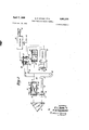
Figure 1 is a schematic view of the fractionation column control system of the present invention; and
Figure 2 is a schematic representation of a differential refractometer suitable for use in the control system of Figure 1.
Referringnow to the drawing in detail and to Figure 1- in particular, there is shown a fractionation column 10 which is supplied with an input feed stream through a line 11 which enters an intermediate section of column 10. This feed stream enters the column at a predetermined rate which is maintained by arate-of-flow controller 12 which adjusts a valve 13 in line 11 in response to the pressure differential across an orifice 14 in line 11 upstream from valve 13. Heat is supplied to column 10 by a steam coil 16 disposed within the lower portion ofthe column. Steam is passed into coil 16 through a line 17 at a rate which is adjusted by a liquid level controller 18 which is actuated by the level of liquid in the bottom of column 10. Controller 18 regulates a valve 19 in line 17 to supply steam at a rate sufiicient to maintain a predetermined level of liquid within column 10. The spent steam from coil 16 is removed through an outlet line 21.
A vapor stream is removed from the top of column 10 through a line 22 which passes through a valve 23 and a cooler 24 into a reflux accumulator 25. A second bypass line 26 having a valve 27 therein communicates between line 22 and accumulator 25. Valve 23 is regulated by a pressure recorder-controller 28 which adjusts valve 23 in response to the pressure in line 22. Valve 27 is regulated by a pressure recorder-controller 30 which adjusts valve 27 in response to the pressure in accumulator 25. Valves 23 and 27 thus control the relative amount of overhead vapor that is condensed by cooler 24 so as to maintain a desired operating pressure on the top of column 10. The condensed vapor in accumulator 25 is removed through a line 31 having a pump 32 therein. A portion of the liquid pumped through line 31 passes through a reflux line 33 back into the upper portion of column 10. A constant rate of flow is maintained in line 33 by a rate-of-fiow controller 35 which adjusts a valve 36 in line 33 in response to the pressure difierential across an orifice 37 disposed in line 33 upstream from valve 36. The remainder of the liquid pumped through line 31 passes through an overhead product line 39. The rate of flow through line 39 is maintained at a value which is a function of the level of liquid in accumulator 25 by means of a liquid level controller 40 which adjusts a valve 41 in line 39 in response to the liquid level in accumulator 25.
A kettle product is removed from column 10 by a line 43 having a pump 44 therein. A sample stream is re moved from the upper portion of column 10 through a line 46 which communicates with a differential refractometer 47. From differential refractometer 47, this sample is vented through a line 48. Dilferential refractometer 47 provides an output signal that is a function of the refractive index of the sample stream circulated therethrough. This signal is applied to a pressure controller 50 which provides a proportional output air pressure to a rate-of-flow recorder-controller 51. The output signal from controller 51 adjusts a valve 52 in line 43 to regulate the rate of withdrawal of kettle product from column 10. This rate of withdrawal is adjusted so that the refractive indexof the sample stream removed through line 46 remains constant at a predetermined value. As long as this sample stream has a constant refractive index it is known that column is operating in a uniform manner.
A suitable differential refractometer. which can be employed in this invention is illustrated schematicallydn Figure 2. The refractoineter comprises a source of light 60 mounted in a housing 61; Source 60 can be an ordinary incandescent bulb emitting radiation in the visible spectrum. Light emitted from source60 passes through a first aperture 62 and thence through a converging lens 63. A"narrow beam of light emerges from housing 61 through a second aperture 64 and is directed through a refractometer cell arrangement 65. The purpose of aperture 62 is to. reduce the'total transmitted radiation from source 60, to avoid excessive heating of the cell arrangement. The filament of source 60 is near the focal point of lens 63, but slightly therebeyond; and aperture 64 is disposed in close proximity to lens 63. Cell 65 includes a first chamber 66 connected to inlet line 46 and outlet vent line 48 through which a sample ofthe liquid from column 10 is circulated. Cell 65 also includes a second chamber 67 provided with an inlet conduit 68 and an outlet conduit 69 which are. adapted for filling. chamber 67 with a standard liquid having a refractive index approximating. the refractive index of one of the components of the mixture being separated. Chambers 66 and 67 are separated by a diagonal transverse plate 70 constructed of a material such as glass which is transparent to the light beam from source 60. A converging. lens 71 defines one opening of chamber 67 and a second converging lens 72 defines a corresponding opening of chamber 66. The, components thus far described are arranged such that the aperture 64 is at the effective principal focus of lens 71. In this manner a narrow beam of parallel light enters chamber 67 and emerges from chamber 66 through lens 72 after passing through diagonal plate 70.
The light beam emerging from lens 72 enters a glass prism 74 disposed such that its front surface is perpendicular to the path of light. The light beam is twice reflected.
in prism 72 and emerges therefrom to pass through a rotatable block of glass 75 having its two surfaces substantially perpendicular to the path of. radiation. From glass block 75, the light beam passes through a second prism 76 disposed such that the light beam normally strikes. the apex in a line perpendicular to base 'A radiation detector unit comprising'firstand second'photo voltaic cells 78 and79 'is' posiitiohed such'tha t the flfi ght beam striking the apex Of'prism '76' normally-impin' es.
equally upon adjacent cells 78"arld 79.. The outpu tsof' cells 78. and 79'aref] connected in opposition by means of electrical leads 80 and 81 so asfto produce a resulting voltage proportional to the difference. intotal radiation incident upon the two cells. The voltage appearing between leads 80 and 81 is amplified by an amplifier 83, the output of which is applied to a reversible motor 84. The shaft of motor 84 carriesa gear 87 which engages a second gear 88. Gear 88 carries a pointer 89'mountedito indicate the degree of rotation of motor 84 produced by the output electrical signal from amplifier 83. i
Glass block 75 is mounted centrally on a rotatable base 91 having a pivotpoiut at the center thereof. Base 91 is provided with an arm 92 which is attached to a cable 93. Cable 93 passes about suitable support posts 94, 95 and 9.6 and is wrapped about the shaft 98 attached to gear 88. Thus, rotation of gear 88 in response to the output signal fromamplifier 83.moves cable 93' to rotate glass block 4. about its mid point. The shaft of motor 84 is also mechanically coupled to pressure controller 50.
If the refractive indices of the gases contained in chambers 66 and 67 are equal, the light beam emerging from cell 65 is in optical alignment with the light beam entering cell 65. The apparatus is positioned initially such that an undeviated light beam strikes the apex of prism 76 and is thereby directed in equal intensities upon cells 78 and 79. However, should the refractive indices of the two gases differ from one another, the emerging light beam is deviated in one direction or the other by cell 65 such that a greater intensity of radiation is incident upon either cell 79 or cell 78. This in turn causes an unbalanced voltage, which after amplification, drives motor 84. The rotation of motor 84 in turn drives shaft 98 to rotate glass block 75 through the connecting linkage cable 93. This rotation of block 75 is such as't'o deviate the light beam in the opposite direction, and continues as long as unequal intensities of radiation are incident upon cells 78 and 79. The degree of this rotation, as indicated by pointer 89, is, therefore, the measure of the difference in refractive indices between the two gases in cell 65, and this rotation also adjusts the output air pressure from controller 50. i
The control system of this invention has been applied to a fractionation column having trays. The input stream passed to column 10 was at a rate of approximately 40,000 gallons per day. Approximately 23,400 gallons per day of liquid were removed as the kettle product through line 43 with approximately 16,600 gallons per day of overhead product being removed through line 39. The reflux passedback to column 10 through line 33 was at a rate of approximately 150,000 gallons, per day. The temperature at the bottom of column 10 was maintained at approximately 245 F; with a top temperature of approximately F; The pressure on the top of column 10 was maintained at approximately 15 pounds per square inch gauge, the bottom pressure beingapp'roximately 36% pounds per square gauge.
In the following table'the composition of the mixture being separated is'given for the feed stream, the kettle product and the overhead product. The refractive indices of the constituents are also given.
. Stream composition, llquld volume percent Refractive Component. index 0 Feed Kettle Overhead product product Normal hexane 2. 6 0. 0 7. 8 1. 3749 Methylcyclopentane. 27. 0 10.0 60. 7 1. 4097 2,2-dimethylpentane 2. 7 1. 6 4. 8 1. 3822 Benr'ene' 0.6 Trace 1. 9 1. 5011 2,4 -d1methylpentane. 5. 0 4. 4 6. 2 1. 3815 Cyclohexane. 59.8 80. 8 17. 9 1. 4262 3,3-dlmethylpentane 0. 5 O. 8 0. 0 1. 3909 1,1- cl1methyleyclopentane 0. 2, 0.0 0. 7 1. 4122 2-methylhexane;; 1. 6 2 4 0. 0 1. 3849 The sample stream circulated through-chamber 661was removed fromthel34th tray from the bottom of column 10. Chamber 67 was filled with methylcyclopentane. Controller 51 adjusted valve 52 to maintain the refrac tive index of the samplestream constant.
While this invention has been described in conjunction with a differential refractometer to analyze a sample stream ,removed from a fractionation column, other continuous analysis instruments can be employed to advantage in some applications. For example, an ultraviolet analyzer such as described in Beckman Bulletin 1228, National Technical Laboratories, South Pasadena, California, can be employed in conjunction with the separation of butadiene from Z-butenes wherein the sample stream preferably is removed from below the point of feed stream entry to the column. In the separation of furfural from Z-butenes, an infrared analyzer such as described in US. Patent 2,579,825 can be employed with the sample stream preferably being removed from below the point of feed stream entry to the column.
Thus, while the invention has been described in conjunction with a present preferred embodiment thereof, it obviously is not limited thereto.
What is claimed is:
l. A fractionation system comprising a fractionation column, means to supply a feed mixture to be separated to said column, a reflux accumulator, a condenser, conduit means to pass overhead vapors from said column through said condenser to said accumulator, means to maintain a predetermined pressure in said column, conduit means to return a portion of the condensed vapors from said accumulator to said column as reflux, conduit means to withdraw a portion of the condensed vapors from said accumulator as an overhead product stream, conduit means to withdraw a kettle product from said column, means to supply heat to the lower region of said column, means to measure the liquid level in the lower region of said column, means responsive to said means to measure liquid level to control the rate of heat addition to said column to tend to maintain the liquid level in said column at a predetermined height, means to withdraw a sample stream from a preselected region of said'column, means to measure the refractive index of said sample stream, and means responsive to said means to measure refractive index to control the rate of kettle product withdrawal through said last mentioned conduit means to tend to maintain the measured refractive index of said sample constant.
2. Afractionation system comprising a fractionation column, means to supply a feed mixture to be separated to said column, a reflux accumulator, a condenser, conduit means to pass overhead vapors from said column through said" condenser to said accumulator, means to maintain a predetermined pressure in said column, conduit means to return a portion of the condensed vapors from said accumulator to said column as reflux, conduit means to withdraw a portion of the condensed vapors from said accumulator as an overhead product stream, conduit means to withdraw a kettle product from said column, means to supply heat to the lower region of said column, means to measure the liquid level in the lower region of said column, means responsive to said means to measure liquid level to control the rate of heat addition to said column to tend to maintain the liquid level in said column at a predetermined height, first and second adjacent sample cells separated by a transparent plate, means to withdraw a sample stream from a preselected region of said column and to direct same through said first sample cell, a reference material disposed in said second sample cell, means to direct a beam of radiation in the range from ultraviolet through infrared through said cells and said plate, means to measure the deviation of the radiation beam transmitted through said cells, and means responsive to said means to measure to control the rate of kettle product withdrawal through said last mentioned conduit-means 'to't'end to. maintain the deviation of the radiation beam constant;
3. A fractionation system comprising a fractionation column, a first conduit communi'ca'tirig-Withsaid' column to supply a feed mixture to be separated, a reflux accumulator, a condenser, a second conduit communicating between the top of said column and said accumulator through, said condenser, means to control the flow through said second conduit in response to the pressurein said column to tend to maintain a constant pressure in said column, a third conduit communicating between the top of said column and said accumulator, a pressure controller to regulate the flow through said third conduit in response to the pressure in said accumulator to tend to maintain a constant pressure in said accumulator, a fourth conduit communicating between said accumulator and the upper region of said column to return condensed vapors to said column as reflux, a flow controller associated with said fourth conduit to tend to maintain a predetermined flow therethrough, a fifth conduit communicating with said accumulator to withdraw an overhead product stream, means responsive to the liquid level in said accumulator to control the flow through said fifth conduit to tend to maintain a predetermined liquid level in said accumulator, means to supply heat to the lower region of said column, a sixth conduit communicating with the bottom of said column to withdraw a kettle product stream, means responsive to the liquid level in the lower region of said column to control the rate of addition of heat to said column to tend to maintain a predetermined liquid level in said column, means to withdraw a sample stream from a preselected region of said column, means to measure the refractive index of said sample stream, and means responsive to said means to measure refractive index to control the rate of kettle product withdrawal through said sixth conduit to tend to maintain the measured refractive index of said sample constant.
4. A fractionation system comprising a fractionation column, a first conduit communicating with said column to supply a feed mixture to be separated, a reflux accumulator, a condenser, a second conduit communicating between the top of said column and said accumulator through said condenser, means to control the flow through said second conduit in response to the pressure in said column to tend to maintain a constant pressure in said column, a third conduit communicating between the top of said column and said accumulator, a pressure controller to regulate the flow through said third conduit in response to the pressure in said accumulator to tend to maintain a constant pressure in said accumulator, a fourth conduit communicating between said accumulator and the upper region of said column to return condensed vapors to said column as reflux, a flow controller associated with said fourth conduit to tend to maintain a predetermined flow therethrough, a fifth conduit communicating with said accumulator to withdraw an overhead product stream, means responsive to the liquid level in said accumulator to control the flow through said fifth conduit to tend to maintain a predetermined liquid level in said accumulator, means to supply heat to the lower region of said column, a sixth conduit communicating with the bottom of said column to withdraw a kettle product stream, means responsive to the liquid level in the lower region of said column to control the rate of addition of heat to said column to tend to maintain a predetermined liquid level in said column, first and second adjacent sample cells separated by a transparent plate, means to withdraw a sample stream from a preselected region of said column and to direct same through said first sample cell, a reference material disposed in said second sample cell, means to direct a beam of radiation in the range from ultraviolet through infrared through said cells and said plate, means to measure the deviation of the radiation beam transmitted through said cells, and means responsive to said means to measure to control the rate of kettle prod- 7 di fl 8 11 xth 'fld iil mii 13 151 53 tain the deviation of th radiatjdn beam dnsuiht'. 2,459,404 2 ,529,030
Meren ces Gited' in the fife of patent UNITED STATES PATENTS 5 1,471,342 Lfig'fi Oct. 23, 1923' 2,180,512 FnK e1 19601211, 1939 2,357,113 Hciughlnd a a1 Aug; 29, 1944 8 -t-"a-ieri- N 391 1 Aiidgtson Ian, 18, 1949 Latchuin Nov. 7, 1950 OTHER REFERENCES Iiisffumnfs' ind Prbcss" Control," published by NLY. Stat; Voatidfil and Practical Arts Assn., 1945.
Petroleu'm'Refiner, vol. 27, No. 11. November 1948.
Claims (1)
1. A FRACTIONATION SYSTEM COMPRISING A FRACTIONATION COLUMN MEANS TO SUPPLY A FEED MIXTURE TO BE SEPARATED TO SAID COLUMN. A REFLUX ACCUMULATOR. A CONDENSER, CONDUIT MEANS TO PASS OVERHEAD VAPORS FROM SAID COLUMN THROUGH SAID CONDENSER TO SAID ACCUMULATOR, MEANS TO MAINTAIN A PREDETERMINED PRESSURE IN SAID COLUMN, CONDUIT MEANS TO RETURN A PORTION OF RTHE CONDDENSED VAPORS FROM SAID ACCUMULATOR TO SAID COLUMN AS REFLUX, CONDUIT MEANS TO WITHDRAW A PORTION OF THE CONDENSED VAPORS FROM SAID ACCUMULATOR AS AN OVERHEAD PRODUCT STREAM, CONDUIT MEANS TO WITHDRAW A KETTLE PRODUCT FROM SAID CONDUIT MEANS TO SUPPLY HEAT TO THE LOWER REGION OF SAID COLUMN, MEANS TO MEASURE THE LIQUID LEVEL IN THE LOWER REGION OF SAID COLUMN, MEANS RESPONSIVE TO SAID MEANS TO MEASURE LIQUID LEVEL TO CONTROL THE RATE OF HEAT
Priority Applications (1)
| Application Number | Priority Date | Filing Date | Title |
|---|---|---|---|
| US401182A US2881118A (en) | 1953-12-30 | 1953-12-30 | Fractionation column control |
Applications Claiming Priority (1)
| Application Number | Priority Date | Filing Date | Title |
|---|---|---|---|
| US401182A US2881118A (en) | 1953-12-30 | 1953-12-30 | Fractionation column control |
Publications (1)
| Publication Number | Publication Date |
|---|---|
| US2881118A true US2881118A (en) | 1959-04-07 |
Family
ID=23586675
Family Applications (1)
| Application Number | Title | Priority Date | Filing Date |
|---|---|---|---|
| US401182A Expired - Lifetime US2881118A (en) | 1953-12-30 | 1953-12-30 | Fractionation column control |
Country Status (1)
| Country | Link |
|---|---|
| US (1) | US2881118A (en) |
Cited By (10)
| Publication number | Priority date | Publication date | Assignee | Title |
|---|---|---|---|---|
| US2992976A (en) * | 1961-07-18 | Polymer recovery from solution | ||
| US2995203A (en) * | 1958-09-08 | 1961-08-08 | Phillips Petroleum Co | Process and apparatus for removing moisture from gases |
| US3164542A (en) * | 1962-10-08 | 1965-01-05 | Phillips Petroleum Co | Catalytic process for the cracking of hydrocarbon oils containing metallic contaminants |
| US3182005A (en) * | 1961-01-03 | 1965-05-04 | Phillips Petroleum Co | Fractionator reboiler heat and bottoms product control system |
| US3212997A (en) * | 1961-03-13 | 1965-10-19 | Phillips Petroleum Co | Automatic control in fractional distillation |
| US3253454A (en) * | 1962-08-17 | 1966-05-31 | Technical Oil Tool Corp | Apparatus and process for continuous determination of percentage boiling point |
| US3417014A (en) * | 1966-10-04 | 1968-12-17 | Phillips Petroleum Co | Method and apparatus for emulsion control |
| US3441485A (en) * | 1964-12-24 | 1969-04-29 | Phillips Petroleum Co | Recovery of streams from a feed by distillation |
| US20080024770A1 (en) * | 2006-07-28 | 2008-01-31 | Shimadzu Corporation | Differential refractive index detector |
| US20150047391A1 (en) * | 2013-08-13 | 2015-02-19 | S & B Engineers And Constructors, Ltd. | Low pressure deethanization process and system |
Citations (6)
| Publication number | Priority date | Publication date | Assignee | Title |
|---|---|---|---|---|
| US1471342A (en) * | 1923-10-23 | Means fob controlling processes of production | ||
| US2180512A (en) * | 1937-08-07 | 1939-11-21 | Pennsylvania Res Corp | Process and apparatus for fractionating |
| US2357113A (en) * | 1940-11-30 | 1944-08-29 | Kellogg M W Co | Apparatus for distillation control |
| US2455243A (en) * | 1945-07-02 | 1948-11-30 | Gulf Research Development Co | Apparatus for automatic control of heat input to stillpots |
| US2459404A (en) * | 1946-03-15 | 1949-01-18 | Standard Oil Dev Co | Method and apparatus for controlling multicomponent separation process in accordancewith light absorption characteristics |
| US2529030A (en) * | 1946-04-25 | 1950-11-07 | Phillips Petroleum Co | Distillation control by refractive index |
-
1953
- 1953-12-30 US US401182A patent/US2881118A/en not_active Expired - Lifetime
Patent Citations (6)
| Publication number | Priority date | Publication date | Assignee | Title |
|---|---|---|---|---|
| US1471342A (en) * | 1923-10-23 | Means fob controlling processes of production | ||
| US2180512A (en) * | 1937-08-07 | 1939-11-21 | Pennsylvania Res Corp | Process and apparatus for fractionating |
| US2357113A (en) * | 1940-11-30 | 1944-08-29 | Kellogg M W Co | Apparatus for distillation control |
| US2455243A (en) * | 1945-07-02 | 1948-11-30 | Gulf Research Development Co | Apparatus for automatic control of heat input to stillpots |
| US2459404A (en) * | 1946-03-15 | 1949-01-18 | Standard Oil Dev Co | Method and apparatus for controlling multicomponent separation process in accordancewith light absorption characteristics |
| US2529030A (en) * | 1946-04-25 | 1950-11-07 | Phillips Petroleum Co | Distillation control by refractive index |
Cited By (11)
| Publication number | Priority date | Publication date | Assignee | Title |
|---|---|---|---|---|
| US2992976A (en) * | 1961-07-18 | Polymer recovery from solution | ||
| US2995203A (en) * | 1958-09-08 | 1961-08-08 | Phillips Petroleum Co | Process and apparatus for removing moisture from gases |
| US3182005A (en) * | 1961-01-03 | 1965-05-04 | Phillips Petroleum Co | Fractionator reboiler heat and bottoms product control system |
| US3212997A (en) * | 1961-03-13 | 1965-10-19 | Phillips Petroleum Co | Automatic control in fractional distillation |
| US3253454A (en) * | 1962-08-17 | 1966-05-31 | Technical Oil Tool Corp | Apparatus and process for continuous determination of percentage boiling point |
| US3164542A (en) * | 1962-10-08 | 1965-01-05 | Phillips Petroleum Co | Catalytic process for the cracking of hydrocarbon oils containing metallic contaminants |
| US3441485A (en) * | 1964-12-24 | 1969-04-29 | Phillips Petroleum Co | Recovery of streams from a feed by distillation |
| US3417014A (en) * | 1966-10-04 | 1968-12-17 | Phillips Petroleum Co | Method and apparatus for emulsion control |
| US20080024770A1 (en) * | 2006-07-28 | 2008-01-31 | Shimadzu Corporation | Differential refractive index detector |
| US7551270B2 (en) * | 2006-07-28 | 2009-06-23 | Shimadzu Corporation | Differential refractive index detector |
| US20150047391A1 (en) * | 2013-08-13 | 2015-02-19 | S & B Engineers And Constructors, Ltd. | Low pressure deethanization process and system |
Similar Documents
| Publication | Publication Date | Title |
|---|---|---|
| US2771149A (en) | Controlling heat value of a fuel gas in a gas separation system | |
| US2764536A (en) | Differential analyzer and control system | |
| US2881118A (en) | Fractionation column control | |
| US2882693A (en) | Control system for separation process | |
| US2529030A (en) | Distillation control by refractive index | |
| US2086808A (en) | Fractionator control device | |
| US2709678A (en) | Distillation control system | |
| US2459404A (en) | Method and apparatus for controlling multicomponent separation process in accordancewith light absorption characteristics | |
| US2022809A (en) | Method fob fractionation control | |
| US2357113A (en) | Apparatus for distillation control | |
| US2977289A (en) | Fractionation process control | |
| US2456398A (en) | Fractionation control apparatus | |
| US3793157A (en) | Method for separating a multicomponent feedstream | |
| US2893927A (en) | Process control system | |
| US3840437A (en) | Distillation column control method and system | |
| US2868701A (en) | Fluid separation control | |
| US2900334A (en) | Fractionator indicating and control method | |
| US2339026A (en) | Method of and apparatus for measuring and testing the end point of volatile liquids | |
| US2917437A (en) | Fluid separation process control | |
| US3238111A (en) | Minimization of time lag in the automatic control of a fractional distillation system | |
| US2885863A (en) | Control system for separation processes | |
| US2890156A (en) | Fractionation column control | |
| US2767133A (en) | Fractionation process and apparatus | |
| US3021263A (en) | Fractionation column control | |
| US3085153A (en) | Control system for separation processes |