US2880098A - Refractory articles and compositions therefor - Google Patents
Refractory articles and compositions therefor Download PDFInfo
- Publication number
- US2880098A US2880098A US579845A US57984556A US2880098A US 2880098 A US2880098 A US 2880098A US 579845 A US579845 A US 579845A US 57984556 A US57984556 A US 57984556A US 2880098 A US2880098 A US 2880098A
- Authority
- US
- United States
- Prior art keywords
- clay
- refractory
- weight
- composition
- mesh
- Prior art date
- Legal status (The legal status is an assumption and is not a legal conclusion. Google has not performed a legal analysis and makes no representation as to the accuracy of the status listed.)
- Expired - Lifetime
Links
- 239000000203 mixture Substances 0.000 title claims description 84
- 239000004927 clay Substances 0.000 claims description 70
- VYPSYNLAJGMNEJ-UHFFFAOYSA-N Silicium dioxide Chemical compound O=[Si]=O VYPSYNLAJGMNEJ-UHFFFAOYSA-N 0.000 claims description 48
- 239000005350 fused silica glass Substances 0.000 claims description 39
- 239000002245 particle Substances 0.000 claims description 21
- 239000005357 flat glass Substances 0.000 claims description 17
- 239000007787 solid Substances 0.000 claims description 12
- 238000002360 preparation method Methods 0.000 claims description 9
- 239000000463 material Substances 0.000 claims description 6
- 239000000377 silicon dioxide Substances 0.000 claims description 4
- 229910052878 cordierite Inorganic materials 0.000 claims description 3
- JSKIRARMQDRGJZ-UHFFFAOYSA-N dimagnesium dioxido-bis[(1-oxido-3-oxo-2,4,6,8,9-pentaoxa-1,3-disila-5,7-dialuminabicyclo[3.3.1]nonan-7-yl)oxy]silane Chemical compound [Mg++].[Mg++].[O-][Si]([O-])(O[Al]1O[Al]2O[Si](=O)O[Si]([O-])(O1)O2)O[Al]1O[Al]2O[Si](=O)O[Si]([O-])(O1)O2 JSKIRARMQDRGJZ-UHFFFAOYSA-N 0.000 claims description 3
- 238000000034 method Methods 0.000 description 20
- 238000010304 firing Methods 0.000 description 15
- 238000000576 coating method Methods 0.000 description 12
- XLYOFNOQVPJJNP-UHFFFAOYSA-N water Substances O XLYOFNOQVPJJNP-UHFFFAOYSA-N 0.000 description 12
- 238000005336 cracking Methods 0.000 description 9
- 239000011819 refractory material Substances 0.000 description 8
- 238000004901 spalling Methods 0.000 description 8
- 239000011449 brick Substances 0.000 description 7
- 239000011248 coating agent Substances 0.000 description 7
- 239000011521 glass Substances 0.000 description 7
- 238000004519 manufacturing process Methods 0.000 description 6
- 239000004615 ingredient Substances 0.000 description 5
- 239000010443 kyanite Substances 0.000 description 5
- 229910052850 kyanite Inorganic materials 0.000 description 5
- 230000035939 shock Effects 0.000 description 5
- 238000007569 slipcasting Methods 0.000 description 5
- 230000007797 corrosion Effects 0.000 description 4
- 238000005260 corrosion Methods 0.000 description 4
- 239000003792 electrolyte Substances 0.000 description 4
- 239000003517 fume Substances 0.000 description 4
- 239000006060 molten glass Substances 0.000 description 4
- 239000004576 sand Substances 0.000 description 4
- 239000005995 Aluminium silicate Substances 0.000 description 3
- HEMHJVSKTPXQMS-UHFFFAOYSA-M Sodium hydroxide Chemical compound [OH-].[Na+] HEMHJVSKTPXQMS-UHFFFAOYSA-M 0.000 description 3
- 235000012211 aluminium silicate Nutrition 0.000 description 3
- INJRKJPEYSAMPD-UHFFFAOYSA-N aluminum;silicic acid;hydrate Chemical compound O.[Al].[Al].O[Si](O)(O)O INJRKJPEYSAMPD-UHFFFAOYSA-N 0.000 description 3
- 239000010427 ball clay Substances 0.000 description 3
- NLYAJNPCOHFWQQ-UHFFFAOYSA-N kaolin Chemical compound O.O.O=[Al]O[Si](=O)O[Si](=O)O[Al]=O NLYAJNPCOHFWQQ-UHFFFAOYSA-N 0.000 description 3
- 230000015572 biosynthetic process Effects 0.000 description 2
- 239000007767 bonding agent Substances 0.000 description 2
- 238000001035 drying Methods 0.000 description 2
- 238000007493 shaping process Methods 0.000 description 2
- 239000004115 Sodium Silicate Substances 0.000 description 1
- 229910000272 alkali metal oxide Inorganic materials 0.000 description 1
- 238000004458 analytical method Methods 0.000 description 1
- 238000001354 calcination Methods 0.000 description 1
- 239000008199 coating composition Substances 0.000 description 1
- 238000001816 cooling Methods 0.000 description 1
- 230000001419 dependent effect Effects 0.000 description 1
- 238000011049 filling Methods 0.000 description 1
- 238000010438 heat treatment Methods 0.000 description 1
- 229920000136 polysorbate Polymers 0.000 description 1
- 230000000717 retained effect Effects 0.000 description 1
- 238000005029 sieve analysis Methods 0.000 description 1
- NTHWMYGWWRZVTN-UHFFFAOYSA-N sodium silicate Chemical compound [Na+].[Na+].[O-][Si]([O-])=O NTHWMYGWWRZVTN-UHFFFAOYSA-N 0.000 description 1
- 229910052911 sodium silicate Inorganic materials 0.000 description 1
Images
Classifications
-
- C—CHEMISTRY; METALLURGY
- C04—CEMENTS; CONCRETE; ARTIFICIAL STONE; CERAMICS; REFRACTORIES
- C04B—LIME, MAGNESIA; SLAG; CEMENTS; COMPOSITIONS THEREOF, e.g. MORTARS, CONCRETE OR LIKE BUILDING MATERIALS; ARTIFICIAL STONE; CERAMICS; REFRACTORIES; TREATMENT OF NATURAL STONE
- C04B33/00—Clay-wares
- C04B33/02—Preparing or treating the raw materials individually or as batches
Definitions
- This invention relates to refractory articles such as those used in the roof of the forehearth of the apparatus for drawing sheet glass and also relates to compositions for the manufacture of refractory articles.
- a shutoff or cutoff bar or block is mounted to the forehearth of the drawing apparatus.
- Part of the roof hastwo L blocks, i.e., elongated blocks that are substantially L-shaped in vertical section.
- the L blocks are mounted so that the horizontal leg of each extends toward the drawn sheet of glass.
- Such drawing apparatus including L blocks are shown in U.S. Patent No. 2,303,805 of L. B. White et al., granted on December 1, 1942; U.S. Patent No. 2,104,460 of H. L. Halbach, granted on January 4, 1938; and U.S. Patent No. 2,5l9,457 of H. L. Halbach et al., granted on August 22, 1950.
- a draw bar is immersed in the molten glass as shown in the foregoing patents.
- the drawing kiln o1- forehearth is brought up to "temperature with the molten glass provided from the associated glass tank furnace but the cutoff block, the L blocks and the draw bar are not in their appropriate positions in the drawing kiln. Because of the refractory compositions of the draw bar, cutoff block, and L blocks, it has been necessary to prepare them from dried molded articles in a firing kiln near the drawing apparatus. The articles are then maintained in the kiln at the operating temperature of the glass drawing kiln. These articles are then removed from the firing kiln and without substantial cooling are set in position in the drawing kiln when the latter has reached its operating temperature.
- Molten glass is in the drawing kiln. in the glass tank furnace associated with the drawing kiln and flows into the latter. This operation is necessary. to. avoid severe cracking due to thermal shock that would occur if these articles were in position when bringing the drawing apparatus to the operating temperature
- the refractory composition of the L blocks is different from the composition. used for the cutoff block and the draw bar.
- When bringing the drawing apparatus up to tem-' perature the part of top of the forehearth that during. operation is occupied by the L blocks and the span therebetween is covered by refractory cover plates.
- the foregoing sequence of operations for the start up of a drawing apparatus requires considerabletime for setting of the hot L blocks, draw bar and cutoff. block before; the drawing operation can be initiated.
- the thermalshock of refractory compositions of the L blocks heretofore iised resulted in cracking or spalling to an undesirable,
- the refractory compositions heretofore used for the manufacture of L blocks for a drawing apparatus comprised a mixture of 38% by weight of a plastic fire clay (9 mesh to'fines), 22% byweight of a burnt fire clay (4- mesh to fines), 20% by weight of a ground ('4 mesh to fi'ues) burnt refractory material made from sand and 1 the molded article.
- This composition was used to make the L blocks by the conventional stiff mud process. In that processthe stiff mud is rammed in the mold of the requisite shape. The mold is removed from The latter is allowed to dry in the usual manner and then placed in a firing kiln where it is very gradually and uniformly brought up to the firing temperature and then kept at the temperature of the drawing forehearth or kiln until it is to be placed in position as part of the roof of the drawing kiln.
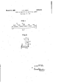
- Fig. 1 is a top plan view of a preferred L block for a Window or sheet glass drawing apparatus and made from the refractory composition of the present invention.
- Fig. 2 is a vertical section along the line 2.2 of Fig.1
- refractory articles such as L blocks and cover plates for a window glass drawing apparatus, having an improved resistance to cracking or spalling when subjected to thermal shock can be prepared by using It has been formed
- the plastic clay a composition comprising about 15 to 45% of a plastic.
- the composition comprises" about 28 to 45% by weight of a plastic clay, about '10 to 52% by weight of a burnt clay and about 20 to 70% by weight of fused silica.
- the composition comprises about 15 to 45% by weight of a plastic clay, about 10 to 65% by weight of burnt clay and about 20 to 70% by weight of fused silica.
- the ratio of the burnt or calcined clay to fused silica be less than 2.
- the burnt or calcined clay are calcined flint, which is a burnt flint clay, burnt kaolin, burnt tire clay, and burnt ball clay, f the compositions of the present inventions can be anyone 'of the clays that are well known to have sufficient plasticity to serve as bonding agents for the preparation of refractories.- In the use of these compositions for the formation of refractory articles, the compositions are used with water for the stiff mud or slip casting techniques.
- the amount of water used is'be'tween about wand 21% by weight based onthe weight of total solids;
- the amount" of water within this range is dependent upon the techf J nique. used as -well'.as" the characteristics and amount of the plastic clay that serves as the bonding agent.
- mixtures of plastic clays can be used to provide the stated percentage of plastic clay and similarly mixtures of burnt clays can be used to provide the recited percentage.
- the plastic clay for the composition used in slip casting process is a clay, such as kaolin and ball clay, that is deflocculated by an electrolyte added to the composition with the water.
- Conventional electrolytes in an amount of about 0.1 to 0.25% by weight (based on Weight of the total solids) is used.
- An example of an electrolyte is a mixture of about 80% by weight of sodium silicate and about 20% by Weight sodium hydroxide.
- the plastic clay has a maximum particle size so that substantially all of it will pass through a 4-mesh screen.
- the calcined or burnt clay and the fused silica likewise should have also a small particle size.
- the L block generally indicated at 10 having the refractory composition of the present invention has coatings 11, 12 and 13 on surfaces 15, 16 and 17, respectively. These coatings are made of a different refractory composition as described. It is noted that coating 13 in the illustrative example covers only a lower part of surface 17 because the upper part of the surface 17 is not exposed to the fumes in a drawing kiln.
- the coatings 77, 12 and 13 are relatively thin, e.g., about inch.
- the stiff mud that is obtained, is rammed into a mold to obtain the L block and the top surface of the rammed mixture is smoothed.
- the mold is disassembled to remove the resultant shaped article. The latter is allowed to dry slightly after which all of the surfaces of the shaped body are smoothed.
- the shaped body is then kept covered with burlaps, that have been wet, for about 90 days until it has dried.
- the dried article is placed in a firing kiln that is at room temperature. The kiln is brought slowly and uniformly up to a temperature of about 2150 F. and the firing schedule to do this takes about to 20 days.
- the fired or burnt article is now ready to be placed in position in the drawing apparatus. This can be done while the L block is still hot.
- the L block can be retained in the kiln and the latter gradually cooled over a period of 7 to 10 days to room temperature.
- the L block at room temperature can be placed in position in the forehearth of the drawing apparatus when rebuilding the drawing kiln or forehearth.
- the preferred L block having the refractory composition as specified above has several of its surfaces coated with a different refractory composition that is resistant to attack by the fumes above the glass in the drawing kiln.
- some of the surfaces of the L block of the composition of the present invention like the composition heretofore used, woud be attacked by the fumes to form products that would drip from the L block into the molten glass, thereby contaminating the
- the material of the refractory coating is preferably a composition comprising plastic clay, calcined kyanite, a burnt clay, such as calcined flint, and a ground burnt refractory material containing sand and burnt clay bonded by plastic fire clay.
- the calcined kyanite provides the corrosion resistance to the refractory composition and is used in substantial amounts such as about 50% by Weight of the mixture and is preferably 6 mesh to fines.
- the plastic clay is preferably Monroe County Fire Clay (8 mesh to fines) and when using this plastic clay it is necessary to use the stiff mud process for forming the coating.
- the calcined flint is used in an amount of 10% by weight.
- ground refractory material is used, in the preferred composition for the coating, in an amount of 5% by weight and is 3 mesh to fines.
- the foregoing composition in the stiff mud process has been used successfully with about 17% by weight of water. The amount of water is based on the weight of the total solids.
- the advantage of using this type of refractory composition containing calcined kyanite in conjunction with the compositions of the invention for the stiff mud process is that the appropriate surfaces of the mold can be first provided with a relatively thin coating of this calcined-kyanite-containing r refractory composition by the stiff mud method before ramming into the mold the invention.
- the L blocks of the present invention can be made by use of slip casting using the appropriate percentages 'of the ingredients specified above. -It is preferred that the coating composition be such that it can be slipcast too and for such slip casting the calcined-kyanite-containing refractory composition uses a plastic clay, such as kaolin or ball clay, that can bedefiocculated by an electrolyte, in lieu of fire clay.
- L blocks for a drawing apparatus and refractory-blocks made by the stiff mud process as described above and using the refractory composition of the invention have been tested under conditions of thermal shock. They were found to be satisfactory, that is, free of cracking and spalling under the conditions used.
- the L blocks have been set in a drawing apparatus while both were at room temperature.
- the drawing apparatus was brought up to temperature and the hot cutofi block and draw bar were transferred from a firing kiln to the drawing kiln and placed in position. To insert the draw bar it was necessary to temporarily reposition one of the L-blocks and then return it to its proper position.
- This brick performed as well as a refractory brick made by the stiff mud process using a composition consisting of 85% fused silica and 15% plastic clay and illustrates that the use of the burnt clay in combination with the fused silica bonded by a plastic clay can produce a product having quite satisfactory resistance to cracking and spalling.
- the ratio of burnt clay to the fused silica in the compositions should not be too high and preferably should be less than 2.
- the fired or calcined refractory articles made from the compositions of this invention will contain about 20 to 70% of fused silica and about to 30% of burnt clay because the plastic clay used to bond the mixture of burnt clay and fused silica is converted to burnt clay during the firing of the dried article obtained from the stiff mud. or slip cast method.
- the composition ofthe illustrative example will provide a refractory article after firing, i.e., calcining, that is one third each of calcined fire clay, calcined flint and fused silica.
- Fused silica' has been described as one of the ingredients in the illustrative example as well as in the description of the compositions presenting the various ranges of the ingredients of the invention.
- Fused silica hasthe composition SiO in amorphous or noncrystalline condition.
- Other refractory materials that also have a substantially uniform coefficient of expansion up to a tem-- 'perature of at least about 2400 F. with less than 0.4% expansion due to increase in temperature from room temperature to 2000 F. can be used in the range specified for fused silica and with the other ingredients the ranges are specified above.
- cordierite a magnesia-alumina-silica, essentially 2MgO.2A1- 0 .5SiO- and lithia-alumina-silica
- a composition for the preparation of a refractory L block for a sheet glass drawing apparatus which comprises a mixture of solids consisting essentially of about 15 to 45% by weight of a plastic clay, about 10 to 65% by weight of a burnt clay and about 20 to 70% by weight of a refractory material selected from the group consisting of fused silica, cordierite and lithia-alumina-silica, said refractory material being in the form of particles having a maximum size of about 9 mesh and a major portion of said refractory material being present as particles larger than mesh.
- a composition for the preparation of a refractory L block for a sheet glass drawing apparatus which comprises a mixture of solids consisting essentially of about 15 to 45 by weight of a plastic clay, about 10 to 65% by weight of a burnt clay and about 20 to 70% by weight of fused silica, said fused silica being in the form of particles having a maximum size of about 9 mesh and a major portion of said fused silica being present as particles larger than 100 mesh.
- composition of claim 2 wherein a major portion of the fused silica is particles larger than 48 mesh.
- a composition for the preparation of a refractory L block for a sheet glass drawing apparatus which comprises a mixture of solids consisting essentially of about one third by weight of a plastic clay, about one third by weight of a burnt clay and about one third by weight of fused silica, said fused silica being in the form of particles having a maximum size of about 9 mesh and a major portion of said fused silica being present as particles larger than 100 mesh.
- a composition for the preparation of a refractory L block for a sheet glass drawing apparatus which consists essentially of about 10 to 21% by weight of water and a mixture of solids consisting essentially of about 15 to 45% by weight of a plastic clay, about 10 to 65% by weight of a burnt clay and about 20 to 70% by weight of fused silica, said fused silica being in the form of particles having a maximum size of about 9 mesh and a major portion of said fused silica being present as particles larger than 100 mesh, said water content being based on the total weight of said plastic clay, burnt clay and fused silica.
- a composition for the preparation of a refractory L block for a sheet glass drawing apparatus which comprises about 10 to 21% by weight of water and a mixture of solids consisting essentially of about one third by Weight of a plastic clay, about one third by weight of a burnt clay and about one third by weight of fused silica, said fused silica being in the form of particles having a maximum size of about 9 mesh and a major portion of said fused silica being present as particles larger than 100 mesh, said water content being based on the total weight of said plastic clay, burnt clay and fused silica.
- a process for the manufacture of an L block for a sheet glass drawing apparatus which comprises forming the composition of claim 6, shaping the composition to the approximate configuration of the refractory L block, drying the shaped product and firing the dried product at a maximum temperature of about 2150 F. to produce the refractory L block.
- a process for the manufacture of an L block for a sheet glass drawing apparatus which comprises forming the composition of claim 7, shaping the composition to the approximate configuration of the refractory L block, drying the shaped product and firing the dried product at a maximum temperature of about 2150 F. to produce the refractory L block.
- a refractory L block for a sheet glass drawing apparatus said L block having a composition comprising 20 to by weight of particles of fused silica and the balance burnt clay, said particles having a maximum particle size of about 9 mesh and the major portion of said fused silica being present as particles larger than mesh.
Landscapes
- Chemical & Material Sciences (AREA)
- Engineering & Computer Science (AREA)
- Ceramic Engineering (AREA)
- Dispersion Chemistry (AREA)
- Materials Engineering (AREA)
- Structural Engineering (AREA)
- Organic Chemistry (AREA)
- Compositions Of Oxide Ceramics (AREA)
Description
March 31, 1959 INVENTOR.
RICHARD E. JONES ATTORNEY U it d S ?$..,1 mO
burgh Plate Glass Company, a corporation of Pennsylvania Application April 23, 1956, Serial No. 579,845 14 Claims. (Cl. 106-68) Pa., assignor to Pitts- Allegheny County, Pa.,
---This invention relates to refractory articles such as those used in the roof of the forehearth of the apparatus for drawing sheet glass and also relates to compositions for the manufacture of refractory articles.
In the manufacture of window glass by drawing operations a shutoff or cutoff bar or block is mounted to the forehearth of the drawing apparatus. Part of the roof hastwo L blocks, i.e., elongated blocks that are substantially L-shaped in vertical section. The L blocks are mounted so that the horizontal leg of each extends toward the drawn sheet of glass. Such drawing apparatus including L blocks are shown in U.S. Patent No. 2,303,805 of L. B. White et al., granted on December 1, 1942; U.S. Patent No. 2,104,460 of H. L. Halbach, granted on January 4, 1938; and U.S. Patent No. 2,5l9,457 of H. L. Halbach et al., granted on August 22, 1950. In the conventional drawing apparatus a draw bar is immersed in the molten glass as shown in the foregoing patents.
(To start the operation of a glass drawing apparatus heretofore, the drawing kiln o1- forehearth is brought up to "temperature with the molten glass provided from the associated glass tank furnace but the cutoff block, the L blocks and the draw bar are not in their appropriate positions in the drawing kiln. Because of the refractory compositions of the draw bar, cutoff block, and L blocks, it has been necessary to prepare them from dried molded articles in a firing kiln near the drawing apparatus. The articles are then maintained in the kiln at the operating temperature of the glass drawing kiln. These articles are then removed from the firing kiln and without substantial cooling are set in position in the drawing kiln when the latter has reached its operating temperature. Molten glass is in the drawing kiln. in the glass tank furnace associated with the drawing kiln and flows into the latter. This operation is necessary. to. avoid severe cracking due to thermal shock that would occur if these articles were in position when bringing the drawing apparatus to the operating temperature The refractory composition of the L blocks is different from the composition. used for the cutoff block and the draw bar. When bringing the drawing apparatus up to tem-' perature the part of top of the forehearth that during. operation is occupied by the L blocks and the span therebetween is covered by refractory cover plates. The foregoing sequence of operations for the start up of a drawing apparatus requires considerabletime for setting of the hot L blocks, draw bar and cutoff. block before; the drawing operation can be initiated. The thermalshock of refractory compositions of the L blocks heretofore iised resulted in cracking or spalling to an undesirable,
extent even when moved from a hot firing kiln to the drawing kiln and set in place as soon as possible.
The refractory compositions heretofore used for the manufacture of L blocks for a drawing apparatus comprised a mixture of 38% by weight of a plastic fire clay (9 mesh to'fines), 22% byweight of a burnt fire clay (4- mesh to fines), 20% by weight of a ground ('4 mesh to fi'ues) burnt refractory material made from sand and 1 the molded article.
tory compositions for the Patented Mar. 31 1958 2 burnt clay bonded by plastic fire clay, 4% by weight of handing sand (48 mesh to fines) and 16% by weight of agate sand (100 mesh to fines). This composition was used to make the L blocks by the conventional stiff mud process. In that processthe stiff mud is rammed in the mold of the requisite shape. The mold is removed from The latter is allowed to dry in the usual manner and then placed in a firing kiln where it is very gradually and uniformly brought up to the firing temperature and then kept at the temperature of the drawing forehearth or kiln until it is to be placed in position as part of the roof of the drawing kiln.
It is an object of the present invention to provide'refractory compositions that can be used to make refractory articles that have improved resistance to cracking and spalling when subjected to thermal shock. H i
It is another object of the invention toprovide refrac: manufacture of L blocks for sheet glass drawing apparatus that can be placed at room temperature in position in the drawing apparatus prior to bringing the drawing apparatus up to the operating temperature.
' heating of a window glass It is a further object of the present invention to pro vide L blocks for sheet glass drawing apparatus that can be stored at room temperature rather than in a firingkiln and then positionedgin the drawing kiln before the forehearth at the start up of the drawing apparatus.
These and other objects of parent to one skilled in the art this invention will, besap from the following descrip tion taken in cornunction with the drawing in which:
. Fig. 1 is a top plan view of a preferred L block for a Window or sheet glass drawing apparatus and made from the refractory composition of the present invention; and
Fig. 2 is a vertical section along the line 2.2 of Fig.1
and shows a refractory coating of a different composition onthose sides of the L block exposed tofumes ina drawing kiln. v
I have found that refractory articles, such as L blocks and cover plates for a window glass drawing apparatus, having an improved resistance to cracking or spalling when subjected to thermal shock can be prepared by using It has been formed The plastic clay a composition comprising about 15 to 45% of a plastic.
clay, about 10 to 65% of a burnt clay and about 20 to 70% of fused silica. These percentages are by weight of the total dry solids of the composition. When this composition isused for forming refractory articles by the conventional stiff mud process, the composition comprises" about 28 to 45% by weight of a plastic clay, about '10 to 52% by weight of a burnt clay and about 20 to 70% by weight of fused silica. When the composition is used for the formation of refractory articles by the convert tional slip casting method the composition comprises about 15 to 45% by weight of a plastic clay, about 10 to 65% by weight of burnt clay and about 20 to 70% by weight of fused silica.
In the foregoing compositions of the invention it .is preferred that the ratio of the burnt or calcined clay to fused silica be less than 2. Examples of the burnt or calcined clay are calcined flint, which is a burnt flint clay, burnt kaolin, burnt tire clay, and burnt ball clay, f the compositions of the present inventions can be anyone 'of the clays that are well known to have sufficient plasticity to serve as bonding agents for the preparation of refractories.- In the use of these compositions for the formation of refractory articles, the compositions are used with water for the stiff mud or slip casting techniques. For both processes the amount of water used is'be'tween about wand 21% by weight based onthe weight of total solids; The amount" of water within this range is dependent upon the techf J nique. used as -well'.as" the characteristics and amount of the plastic clay that serves as the bonding agent. Furthermore, mixtures of plastic clays can be used to provide the stated percentage of plastic clay and similarly mixtures of burnt clays can be used to provide the recited percentage. The plastic clay for the composition used in slip casting process is a clay, such as kaolin and ball clay, that is deflocculated by an electrolyte added to the composition with the water. Conventional electrolytes in an amount of about 0.1 to 0.25% by weight (based on Weight of the total solids) is used. An example of an electrolyte is a mixture of about 80% by weight of sodium silicate and about 20% by Weight sodium hydroxide.
In the foregoing compositions of the present invention the plastic clay has a maximum particle size so that substantially all of it will pass through a 4-mesh screen. Preferably all of the plastic clay in the mixture of solids will pass through a 9-mesh screen. The calcined or burnt clay and the fused silica likewise should have also a small particle size.
The L block generally indicated at 10 having the refractory composition of the present invention has coatings 11, 12 and 13 on surfaces 15, 16 and 17, respectively. These coatings are made of a different refractory composition as described. It is noted that coating 13 in the illustrative example covers only a lower part of surface 17 because the upper part of the surface 17 is not exposed to the fumes in a drawing kiln. The coatings 77, 12 and 13 are relatively thin, e.g., about inch.
The following is an illustrative example of the preparation of the L block of Figs. 1 and 2 from one of the preferred compositions of the present invention using the stiff mud process. There is prepared a mixture of 33 /3 by weight of fire clay (9 mesh to fines), 33 /3 by weight of calcined flint, (4 mesh to fines) and 33 /3 by weight of fused silica (9 mesh to fines). The plastic clay is Monroe County Fire Clay, which is a fire clay obtained commercially from Monroe County, Missouri. The calcined flint is known as Calcined Flint Pennsylvania. Fused silica as commercially available is in lump form and is placed in a crusher-grader to obtain material that has a particle size specified above. This mixture is then mixed with 13% by weight, based on the weight of the total solids, of water.
The stiff mud, that is obtained, is rammed into a mold to obtain the L block and the top surface of the rammed mixture is smoothed. The mold is disassembled to remove the resultant shaped article. The latter is allowed to dry slightly after which all of the surfaces of the shaped body are smoothed. The shaped body is then kept covered with burlaps, that have been wet, for about 90 days until it has dried. The dried article is placed in a firing kiln that is at room temperature. The kiln is brought slowly and uniformly up to a temperature of about 2150 F. and the firing schedule to do this takes about to 20 days. The fired or burnt article is now ready to be placed in position in the drawing apparatus. This can be done while the L block is still hot. Alternately, the L block can be retained in the kiln and the latter gradually cooled over a period of 7 to 10 days to room temperature. The L block at room temperature can be placed in position in the forehearth of the drawing apparatus when rebuilding the drawing kiln or forehearth.
As seen in Fig. 2 the preferred L block having the refractory composition as specified above has several of its surfaces coated with a different refractory composition that is resistant to attack by the fumes above the glass in the drawing kiln. In the absence of such a refractory coating some of the surfaces of the L block of the composition of the present invention, like the composition heretofore used, woud be attacked by the fumes to form products that would drip from the L block into the molten glass, thereby contaminating the The material of the refractory coating is preferably a composition comprising plastic clay, calcined kyanite, a burnt clay, such as calcined flint, and a ground burnt refractory material containing sand and burnt clay bonded by plastic fire clay. The calcined kyanite provides the corrosion resistance to the refractory composition and is used in substantial amounts such as about 50% by Weight of the mixture and is preferably 6 mesh to fines. The plastic clay is preferably Monroe County Fire Clay (8 mesh to fines) and when using this plastic clay it is necessary to use the stiff mud process for forming the coating. The calcined flint is used in an amount of 10% by weight. The fourth ingredient, the burnt latter.
ground refractory material is used, in the preferred composition for the coating, in an amount of 5% by weight and is 3 mesh to fines. The foregoing composition in the stiff mud process has been used successfully with about 17% by weight of water. The amount of water is based on the weight of the total solids. The advantage of using this type of refractory composition containing calcined kyanite in conjunction with the compositions of the invention for the stiff mud process is that the appropriate surfaces of the mold can be first provided with a relatively thin coating of this calcined-kyanite-containing r refractory composition by the stiff mud method before ramming into the mold the invention.
The following is the sieve analysis of the refractory composition used with water in the stiff mud process of the foregoing illustrative example for the preparation of refractory articles, such as L blocks, by the stifif mud process.
stiff mud composition of the Percent On 4 mesh 0.3 On 6 mesh 5.1 On 8 mesh 5.6 On 10 mesh 6.1 On 14 mesh 6.0 On 28 mesh 16.0 On 48 mesh 10.2 On mesh 7.5 On 200 mesh 4.7 Through 200 mesh 37.9
Sieve analyses of suitable fire clay, calcined flint and fused silica for use in the illustrative example are as Percent SiO 68.25 A1 0 25.35
F8203 TiO 1.50 'CaO 0.23 MgO 0.22 Alkali oxide 0.64 Loss on ignition 3.29
The following are the propertiesof the refractory article of the illustrative'example: Modulus of rupture, before firing, p.s.i.,
at room temperature 163 PCE:
Cone 29+ F. 2984+ Porosity, percent:
.Cone 08 24.6 Cone 4 23.7 Burning shrinkage, percent:
Cone 08 0.1 Cone 4 0.7 Modulus of rupture, after firing to cone indicated, p.s.i., at room temperature:. Cone 08 399 Cone 4 564 The L blocks of the present invention can be made by use of slip casting using the appropriate percentages 'of the ingredients specified above. -It is preferred that the coating composition be such that it can be slipcast too and for such slip casting the calcined-kyanite-containing refractory composition uses a plastic clay, such as kaolin or ball clay, that can bedefiocculated by an electrolyte, in lieu of fire clay.
s L blocks for a drawing apparatus, and refractory-blocks made by the stiff mud process as described above and using the refractory composition of the invention have been tested under conditions of thermal shock. They were found to be satisfactory, that is, free of cracking and spalling under the conditions used. The L blocks have been set in a drawing apparatus while both were at room temperature. The drawing apparatus was brought up to temperature and the hot cutofi block and draw bar were transferred from a firing kiln to the drawing kiln and placed in position. To insert the draw bar it was necessary to temporarily reposition one of the L-blocks and then return it to its proper position. In each case the drawing apparatus has been operated satisfactorily without the cracking and spalling heretofore obtained wth the refractory L blocks of the composition of the prior art mentioned above. The cracking and spalling of the previous L blocks occurred to some extent even though these L blocks had been kept at an elevated temperature in the firing kiln until the drawing apparatus was brought up to temperature and then positioned in the latter.
In a research glass corrosion tank it had been customary to cover the dog-house filling hole with a brick. When the cover brick was an ordinary high-duty fire clay brick, it was necessary to replace it after a few hours of use. The cover block was subjected to a heavy thermal shock in this corrosion tank because fire clay brick was removed every half hour to add batch to the furnace. When the cover block was in place it was subjected to the furnace temperature on one side and to room temperature on the other. This use serves as a good test for resistance to cracking and spalling of a refractory article. A brick made with the refractory composition of the illustrative example by the stiff mud process was used as the cover block. It was used satisfactorily for 22 weeks. It was removed only because of its corrosion by the furnace fumes. This brick performed as well as a refractory brick made by the stiff mud process using a composition consisting of 85% fused silica and 15% plastic clay and illustrates that the use of the burnt clay in combination with the fused silica bonded by a plastic clay can produce a product having quite satisfactory resistance to cracking and spalling. The ratio of burnt clay to the fused silica in the compositions should not be too high and preferably should be less than 2. These compositions of the invention are more refractory than that made with a considerably higher fused silica content.
There is obtained a similar improvement in other refractory articles, such as cover tiles. or plates for drawing kilns, when the compositions of the present invention are used to make the refractory articles.
It is apparent from the foregoing that the fired or calcined refractory articles made from the compositions of this invention will contain about 20 to 70% of fused silica and about to 30% of burnt clay because the plastic clay used to bond the mixture of burnt clay and fused silica is converted to burnt clay during the firing of the dried article obtained from the stiff mud. or slip cast method. Also, of course, the composition ofthe illustrative example will provide a refractory article after firing, i.e., calcining, that is one third each of calcined fire clay, calcined flint and fused silica.
Fused silica' has been described as one of the ingredients in the illustrative example as well as in the description of the compositions presenting the various ranges of the ingredients of the invention. Fused silica hasthe composition SiO in amorphous or noncrystalline condition. Other refractory materials that also have a substantially uniform coefficient of expansion up to a tem-- 'perature of at least about 2400 F. with less than 0.4% expansion due to increase in temperature from room temperature to 2000 F. can be used in the range specified for fused silica and with the other ingredients the ranges are specified above. Examples of such materials are cordierite (a magnesia-alumina-silica, essentially 2MgO.2A1- 0 .5SiO- and lithia-alumina-silica The foregoing description is for the purpose of illustration only and the invention is limited only by the claims that follow.
1 claim:
1. A composition for the preparation of a refractory L block for a sheet glass drawing apparatus which comprises a mixture of solids consisting essentially of about 15 to 45% by weight of a plastic clay, about 10 to 65% by weight of a burnt clay and about 20 to 70% by weight of a refractory material selected from the group consisting of fused silica, cordierite and lithia-alumina-silica, said refractory material being in the form of particles having a maximum size of about 9 mesh and a major portion of said refractory material being present as particles larger than mesh.
2. A composition for the preparation of a refractory L block for a sheet glass drawing apparatus which comprises a mixture of solids consisting essentially of about 15 to 45 by weight of a plastic clay, about 10 to 65% by weight of a burnt clay and about 20 to 70% by weight of fused silica, said fused silica being in the form of particles having a maximum size of about 9 mesh and a major portion of said fused silica being present as particles larger than 100 mesh.
3. The composition of claim 2 wherein a major portion of the fused silica is particles larger than 48 mesh.
4. A composition for the preparation of a refractory L block for a sheet glass drawing apparatus which comprises a mixture of solids consisting essentially of about one third by weight of a plastic clay, about one third by weight of a burnt clay and about one third by weight of fused silica, said fused silica being in the form of particles having a maximum size of about 9 mesh and a major portion of said fused silica being present as particles larger than 100 mesh.
5. The composition of claim 4 wherein the plastic clay is fire clay and the burnt clay is calcined fiint.
6. A composition for the preparation of a refractory L block for a sheet glass drawing apparatus which consists essentially of about 10 to 21% by weight of water and a mixture of solids consisting essentially of about 15 to 45% by weight of a plastic clay, about 10 to 65% by weight of a burnt clay and about 20 to 70% by weight of fused silica, said fused silica being in the form of particles having a maximum size of about 9 mesh and a major portion of said fused silica being present as particles larger than 100 mesh, said water content being based on the total weight of said plastic clay, burnt clay and fused silica.
7. A composition for the preparation of a refractory L block for a sheet glass drawing apparatus which comprises about 10 to 21% by weight of water and a mixture of solids consisting essentially of about one third by Weight of a plastic clay, about one third by weight of a burnt clay and about one third by weight of fused silica, said fused silica being in the form of particles having a maximum size of about 9 mesh and a major portion of said fused silica being present as particles larger than 100 mesh, said water content being based on the total weight of said plastic clay, burnt clay and fused silica.
8. The composition of claim 7 wherein the plastic clay is fire clay and the burnt clay is calcined flint.
9. A process for the manufacture of an L block for a sheet glass drawing apparatus which comprises forming the composition of claim 6, shaping the composition to the approximate configuration of the refractory L block, drying the shaped product and firing the dried product at a maximum temperature of about 2150 F. to produce the refractory L block.
10. A process for the manufacture of an L block for a sheet glass drawing apparatus which comprises forming the composition of claim 7, shaping the composition to the approximate configuration of the refractory L block, drying the shaped product and firing the dried product at a maximum temperature of about 2150 F. to produce the refractory L block.
11. The process of claim 10 wherein the plastic clay is fire clay and the burnt clay is calcined flint.
12. A refractory L block for a sheet glass drawing apparatus, said L block having a composition comprising 20 to by weight of particles of fused silica and the balance burnt clay, said particles having a maximum particle size of about 9 mesh and the major portion of said fused silica being present as particles larger than mesh.
13. The refractory L block of claim 12 wherein the major portion of the fused silica is particles larger than 48 mesh.
14. The refractory L block of claim 12 wherein the fused silica constitutes about one third by Weight of the composition.
References Cited in the file of this patent UNITED STATES PATENTS 1,424,120 Rossman July 25, 1922 1,858,317 Willetts May 17, 1932 1,882,701 Alley Oct. 18, 1932 2,339,454 Bradley Jan. 18, 1944 UNITED STATES PATENT OFFICE CERTIFICATE OF CORRECTION Patent No. 2,880,698 March 31, 1959 Richard E Jones It is hereby certified that error appears in the printed specification of the above numbered patent requiring correction and that the said Letters Patent should read as corrected below.
Column B, line 28, for "coatings 77" read coatings ll =3 lines 33,
34 and 35, for "33 1/3", each occurrence, read 33 1/3% Signed and sealed this 29th day of September 1959 (SEAL Attest:
KARL H, AXLINE Attesting Oificer ROBERT C. WATSON Commissioner of Patents
Claims (1)
1. A COMPOSITION FOR THE PREPARATION OF A REFACTORY L BLOCK FOR A SHEET GLASS DRAWING APPARATUS WHICH COMPRISES A MIXTURE OF SOLIDS CONSISTING ESSENTIALLY OF ABOUT 15 TO 45% BY WEIGHT OF A PLASTIC CLAY, ABOUT 10 TO 65% BY WEIGHT OF A BURNT CLAY AND ABOUT 20 TO 70% BY WEIGHT OF A REFACTORY MATERIAL SELECTED FROM THE GROUP CONSISTING OF FUSED SILICA, CORDIERITE AND LITHIA-ALUMINA-SILICA, SAID REFACTORY MATERIAL BEING IN THE FORM OF PARTICLES HAVING A MAXIMUM SIZE OF ABOUT 9 MESH AND A MAJOR PORTION OF SAID REFACTORY MATERIAL BEING PRESENT AS PARTICLES LARGER THAN 100 MESH.
Priority Applications (2)
| Application Number | Priority Date | Filing Date | Title |
|---|---|---|---|
| US579845A US2880098A (en) | 1956-04-23 | 1956-04-23 | Refractory articles and compositions therefor |
| ES0234790A ES234790A1 (en) | 1956-04-23 | 1957-04-11 | Refractory articles and compositions therefor |
Applications Claiming Priority (1)
| Application Number | Priority Date | Filing Date | Title |
|---|---|---|---|
| US579845A US2880098A (en) | 1956-04-23 | 1956-04-23 | Refractory articles and compositions therefor |
Publications (1)
| Publication Number | Publication Date |
|---|---|
| US2880098A true US2880098A (en) | 1959-03-31 |
Family
ID=24318582
Family Applications (1)
| Application Number | Title | Priority Date | Filing Date |
|---|---|---|---|
| US579845A Expired - Lifetime US2880098A (en) | 1956-04-23 | 1956-04-23 | Refractory articles and compositions therefor |
Country Status (2)
| Country | Link |
|---|---|
| US (1) | US2880098A (en) |
| ES (1) | ES234790A1 (en) |
Cited By (6)
| Publication number | Priority date | Publication date | Assignee | Title |
|---|---|---|---|---|
| US3026212A (en) * | 1959-09-25 | 1962-03-20 | Gen Refractories Co | Refractory product and method of manufacture |
| US3183573A (en) * | 1960-07-26 | 1965-05-18 | Nat Tile & Mfg Co | Apparatus for making ceramic bodies and ceramic composition for use therewith |
| US3279930A (en) * | 1964-06-25 | 1966-10-18 | Foote Mineral Co | Ceramic product and its preparation |
| US3751274A (en) * | 1971-08-16 | 1973-08-07 | Gen Refractories Co | Plastic alumina-silica refractory |
| US4194917A (en) * | 1977-06-14 | 1980-03-25 | Asahi Glass Company, Ltd. | Fired ceramic having dense and low thermal expansion characteristics |
| WO1986000292A1 (en) * | 1984-06-21 | 1986-01-16 | Resco Products, Inc. | Medium weight abrasion-resistant castable |
Citations (4)
| Publication number | Priority date | Publication date | Assignee | Title |
|---|---|---|---|---|
| US1424120A (en) * | 1921-05-16 | 1922-07-25 | American Zinc Lead & Smelting | Making of zinc retorts and other refractory shapes |
| US1858317A (en) * | 1928-08-25 | 1932-05-17 | Hartford Empire Co | Refractory for contact with molten glass |
| US1882701A (en) * | 1929-08-22 | 1932-10-18 | American Brake Shoe & Foundry | Refractory composition for brake shoe molds |
| US2339454A (en) * | 1940-12-30 | 1944-01-18 | A P Green Fire Brick Company | Assay crucible and similar article |
-
1956
- 1956-04-23 US US579845A patent/US2880098A/en not_active Expired - Lifetime
-
1957
- 1957-04-11 ES ES0234790A patent/ES234790A1/en not_active Expired
Patent Citations (4)
| Publication number | Priority date | Publication date | Assignee | Title |
|---|---|---|---|---|
| US1424120A (en) * | 1921-05-16 | 1922-07-25 | American Zinc Lead & Smelting | Making of zinc retorts and other refractory shapes |
| US1858317A (en) * | 1928-08-25 | 1932-05-17 | Hartford Empire Co | Refractory for contact with molten glass |
| US1882701A (en) * | 1929-08-22 | 1932-10-18 | American Brake Shoe & Foundry | Refractory composition for brake shoe molds |
| US2339454A (en) * | 1940-12-30 | 1944-01-18 | A P Green Fire Brick Company | Assay crucible and similar article |
Cited By (7)
| Publication number | Priority date | Publication date | Assignee | Title |
|---|---|---|---|---|
| US3026212A (en) * | 1959-09-25 | 1962-03-20 | Gen Refractories Co | Refractory product and method of manufacture |
| US3183573A (en) * | 1960-07-26 | 1965-05-18 | Nat Tile & Mfg Co | Apparatus for making ceramic bodies and ceramic composition for use therewith |
| US3279930A (en) * | 1964-06-25 | 1966-10-18 | Foote Mineral Co | Ceramic product and its preparation |
| US3751274A (en) * | 1971-08-16 | 1973-08-07 | Gen Refractories Co | Plastic alumina-silica refractory |
| US4194917A (en) * | 1977-06-14 | 1980-03-25 | Asahi Glass Company, Ltd. | Fired ceramic having dense and low thermal expansion characteristics |
| WO1986000292A1 (en) * | 1984-06-21 | 1986-01-16 | Resco Products, Inc. | Medium weight abrasion-resistant castable |
| US4687752A (en) * | 1984-06-21 | 1987-08-18 | Resco Products, Inc. | Medium weight abrasion-resistant castable |
Also Published As
| Publication number | Publication date |
|---|---|
| ES234790A1 (en) | 1957-10-01 |
Similar Documents
| Publication | Publication Date | Title |
|---|---|---|
| US3520705A (en) | Non-vitreous ceramic ware made from pseudowollastonite | |
| US2516892A (en) | Refractory concrete | |
| US2880098A (en) | Refractory articles and compositions therefor | |
| US2407135A (en) | Furnace lining | |
| CN107892579A (en) | Calcareous glass furnace molten tin bath suspended roof brick of aluminic acid and preparation method thereof | |
| US1527874A (en) | Refractory product and method of producing same | |
| US2567088A (en) | Refractory material and method of making | |
| US3365318A (en) | Low temperature burned refractory brick and method of making the same | |
| US2314758A (en) | Refractory composition | |
| US3423217A (en) | Method of making ceramic shapes | |
| US3189668A (en) | Method of slip casting basic refractory materials | |
| US2675323A (en) | Refractory materials | |
| US2880097A (en) | Zircon refractory composition and method of making it | |
| US2220412A (en) | Refractory and method of making same | |
| US1897183A (en) | Method of and material employed in the manufacture of refractory | |
| US2425891A (en) | Refractories and method of making | |
| US2036190A (en) | Method of producing a ceramic body | |
| US2079715A (en) | Process and batch for making ceramic bodies | |
| US1818506A (en) | Refractory and method of making the same | |
| US3752682A (en) | Zircon-pyrophyllite unfired refractory bricks and method for the manufacture of the same | |
| US1616192A (en) | Unburned refractory brick and method of making it | |
| US1760360A (en) | Refractory product | |
| US3282579A (en) | Refractory lining | |
| US3726699A (en) | Burned basic refractory and batch therefor | |
| US3384500A (en) | Refractory |