US2877458A - System for dividing a surface of revolution - Google Patents
System for dividing a surface of revolution Download PDFInfo
- Publication number
- US2877458A US2877458A US612074A US61207456A US2877458A US 2877458 A US2877458 A US 2877458A US 612074 A US612074 A US 612074A US 61207456 A US61207456 A US 61207456A US 2877458 A US2877458 A US 2877458A
- Authority
- US
- United States
- Prior art keywords
- pulses
- dividing
- marks
- index
- recording
- Prior art date
- Legal status (The legal status is an assumption and is not a legal conclusion. Google has not performed a legal analysis and makes no representation as to the accuracy of the status listed.)
- Expired - Lifetime
Links
- 238000006073 displacement reaction Methods 0.000 description 9
- 230000002093 peripheral effect Effects 0.000 description 6
- 239000011521 glass Substances 0.000 description 5
- 238000004519 manufacturing process Methods 0.000 description 5
- 230000006872 improvement Effects 0.000 description 4
- 230000005284 excitation Effects 0.000 description 3
- 230000008901 benefit Effects 0.000 description 2
- 230000000694 effects Effects 0.000 description 2
- 230000006870 function Effects 0.000 description 2
- 230000009467 reduction Effects 0.000 description 2
- 230000004044 response Effects 0.000 description 2
- 238000012935 Averaging Methods 0.000 description 1
- 230000008859 change Effects 0.000 description 1
- 238000006243 chemical reaction Methods 0.000 description 1
- 230000005855 radiation Effects 0.000 description 1
Images
Classifications
-
- H—ELECTRICITY
- H03—ELECTRONIC CIRCUITRY
- H03M—CODING; DECODING; CODE CONVERSION IN GENERAL
- H03M1/00—Analogue/digital conversion; Digital/analogue conversion
- H03M1/12—Analogue/digital converters
- H03M1/22—Analogue/digital converters pattern-reading type
- H03M1/24—Analogue/digital converters pattern-reading type using relatively movable reader and disc or strip
- H03M1/28—Analogue/digital converters pattern-reading type using relatively movable reader and disc or strip with non-weighted coding
- H03M1/30—Analogue/digital converters pattern-reading type using relatively movable reader and disc or strip with non-weighted coding incremental
- H03M1/303—Circuits or methods for processing the quadrature signals
- H03M1/305—Circuits or methods for processing the quadrature signals for detecting the direction of movement
Definitions
- This invention relates to a system for dividing a surface such as might be used for example in the production of coding devices for use for analog-digital conversion and is an improvement upon such a system as is disclosed in my prior Patent No. 2,590,110, patented March 25, 1952.
- the present invention relates to an electrical system for dividing a surface such as a disk or drum, into aliquot sectors or parts. It is to be understood however that the principles of the invention may also be applied to linear dividing engines.
- the invention relates to a system for producing a code record device, as for example, a disk, drum or plate, having commutating segments distributed thereon and arranged to quantize the displacement of the device in accordance with .a digital number code.
- apparatus for producing a coding device having commutating elements corresponding to a digital code.
- Said apparatus includes a means for rotatably supporting a photosensitive surface, a means producing an alternating voltage, constituting a frequency reference, means for driving the supporting means at an angular velocity proportional to the frequency of the alternating voltage, means arranged adfor exposing said photoat radii differing by equal increments, and means operable in timed relation to said alternating voltage for exciting the means for exposing the photosensitive surface, to produce commutating segments thereon.
- the present invention associates with the table or supporting means, or makes an integral part thereof, a means for producing electrical pulses in number proportional to the relative displacement of the table or supporting means, and at an instantaneous recurrence rate proportional to the rate of instantaneous displacement.
- the electrical pulses are supplied to the exposing means to excite it into operation.
- Said means makes use of the displacement of the table with respect to the supporting means to produce the synchronizing function and eliminates the need for a special type motor and power source or frequency reference.
- Another object is to provide an improved surface dividing system having means associated therewith for assuring accuracy of operation and duplication of divided surfaces produced on successive cycles of operation.
- Another more specific object of the invention is to provide a surface dividing system having a rotatable support or table, upon which is engraved a peripheral row of index marks, operable to relate the production of pulses to the angular displacement of the table.
- Another object of the invention is to provide a divided surface capable of being operated at different selected speeds and producing the same degree of accuracy in the coded record.
- a still further object of the invention is to permit the use of lower displacement speeds with a consequent reduction in bandwith response requirements of the exposing means utilized in my previous system.
- a still further object of the invention is to eliminate the stringent necessity for constant displacement speeds of my prior patent.
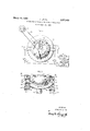
- Fig. 1 is a schematic showing of the various parts and their cooperative relationship to each other.
- Fig. 2 is a more detailed schematic showing of the pickup device and of one ofthe possible adjusted relationships of the pickup devices to the index marks on the table.
- a circular table clear or translucent glass plate 10 thereon The glass plate may be secured to the table 7 by any conventional fastening
- the table 7 is equipped 7 carries a blank may be a sheet or several types of radiation, such as, for example, visible light, ultra-violet light, or x-rays, or the like such as may be produced in pulses of different time duration.
- the photosensitive surface is responsive to visible light. In such instance, the apparatus should be enclosed in a light tight housing or be used in a darkened room.
- the table 7 is rotatably supported, by means not shown, for rotation about its central axis.
- Any conventional support means may be provided, as for example, a shaft may be alfixed perpendicular to the table at its center, and spaced bearings provided for journaling said shaft.
- a lamp or other light source 30 is inclosed within a light tight housing or cavity 31 above the edge of the plate 10.
- the housing is formed with a narrow slit or aperture 32 at the bottom edge thereof in a position'to cooperate with the opaque marks 11.
- a similar housing or cavity 33 incloses a photoelectric pickup device such as a photocell 34 and is providedwith a slit or aperture 35 in the upper portion thereof.
- the apertures-32 and 35 form a narrow light passage between the lamp 3t) and the photocell 34. This passage is of such width and'length as to be substantially blocked by the passage of an opaque index mark 11 on the plate between the two inclosures 30 and 33.
- Fig. '2 also illustrates the location of the pickup devices 12 and 13 relative to the instantaneous position of two index marks,-for one mode of operation.
- the pickupdevicellS isdirected to a point on said table 10 directly over one of the index marks 11 at the same instant that an index mark appears squarely before the viewing means-of the pickup device 12.
- the photocells will respond to the index marks in a manner more fully described hereinafter to produce a number of pulses which are equal to the number of marks that pass the viewing means of said devices.
- the pickups may be provided with multiple slits so that the passage of a mark may result in the production of a number of pulses rather than a single pulse.
- the pulse counter 17 may be a binary counter and may include a series of multivibrator stages connected in cascade and provided with separate outputs 29.
- the first stage of the counter produces a square wave out-put having a frequency equal to one half the pulses per second fed to it from thepickup devices.
- the second stage of the counter has a square wave output having half the frequency of the first stage.
- the third stage has an output frequency equal to half the frequencyof the second stage, the fourth stage half the frequency of the third stage and so on, with each succeeding stage having an output with half the frequency of the preceding stage.
- Each stage of the pulse counter 17 is connected by means 2% to separate modulating-equipment 19, having a further connection 21 to the recording head 22.
- the recording head 22 may be the same as that disclosed in my priorpatent. It is provided with a plurality of lamps, separately housed in a housing havingan aperture opening towards the recording blank 8. The recording head 22 is separately supported relative to the table 7, and extends radially of the table 7 In operation, as the lamps are excited the light emanating from the lamps through the aperture associated therewith, exposes the sensitized surface for an annular distance depending on the duration of such excitation and the rate of speed of the table.
- the duration of the excitation of the separate lamps is definitely related to the angular displacement of the table. It is thus obvious, that thetable may be operated at any desired adjusted speed, and the duration of the separate excitation pulses and its frequency fed tothe separate lamps will be automatically varied accordingly.
- a binary counter is referred to above, one or more stages having division ratio greater than two may be substituted for one or more stages of the binary counter to permit dividing a circle into a number of parts not'a power of two.
- a ternary ring counter stage may be substituted for any binary stage.
- a suitable arrangement of electronic counting stages which indicate the count in the desired binary-coded-decimal language may be used, and the count moduleten maybe used, and the individual binary outputs of the counter may then be connected to the recording head to provide the proper recording signals.
- Such bina'ry-coded-decimal pulse counters are well known to the art and are in common use.
- the number of electrical pulses furnishedto the pulse counter 17 on a fullrevolution of the table be so related to the maximum count of the counter that the counter returns to its original countwhen exactly one revolution is made. In some cases, however, it may be convenient to have the counter go through different sequences of counting on successive revolutions, so thatthe recorded pattern is obtained by the super-po'sition of different patterns recorded on a number of successive revolutions.
- the apparatus of the present invention operates as follows: A blank 8 having a sensitized surface is clamped in place on the table 7 by clamps 9. The table 7 is then set to rotating at a convenient speed. As the index marks move past the viewing means of the photocells, electrical pulses are produced by the photocell, in response to the change in light intensity transmitted from the lamp 30 through the apertures 32 and 35. The pulses are applied to the counter device 17 which provides a successive division of the frequency of said pulses to produce separate outputs Ztl. The separate outputs 20 are fed through separate modulating equipment to the separate lamps in the recording head. The separate lamps are excited for -given length of time depending upon the stage to which each is connected and the angular speed of the table 10.
- the function of thesecond pickup will now be explained. It is of course possible that errors may occur in the production of index marks on the glass plate 10. It is also possible that the plate 10 may be mounted in such a way that it is not absolutely concentric with the sensitized surface 8 or the table 7. This will cause variations in the recurrence rates of the pulses produced by the photoelectric pickup device which in turn will result in inaccuracies in the final exposed disc 8. Additionalphot m electric pickups may be added to eliminate this difficulty by averaging out any such errors in recurrence rate. These additional pickups are represented by the pickup 12.
- Each additional pickup is identical to the structure described for pickup 13 and is so located with respect to the disc it that it would produce an electrical impulse at the same time if the index marks upon the disc were equally spaced and symmetrical to the axis of rotation. For example with an even number of opaque index marks on the disc and two pickups the pickups would be spaced at intervals of about the disc. If an odd number of index marks were used the spacing would be 180 less one half the difference angle between adiacent index marks.
- a system for dividing a surface of revolution into aliquot parts comprising a rotatable support having means clamping a recording surface thereon and index marks arranged thereon, means for rotating said support, means arranged adjacent said index marks and responsive to movement of said marks relative thereto for producing a series of equally spaced signal pulses, means connected to said last named means for converting said signal pulses into a series of pulses having a spacing equal to a multiple of the spacing of said equally spaced pulses, means arranged in juxtaposition to said recording surface for imposing a record thereon and means connecting said last named means and said means for converting said pulses for dividing said surface into aliquot sectors.
- a system for dividing a surface of revolution into aliquot parts comprising a rotatable support having clamping means thereon, a recording surface clamped to said rotatable support, index marks equally spaced along the surface of said support, means arranged adjacent said support and said index marks and responsive thereto to produce a continuing series of electrical pulses, means for converting said series of electrical pulses to a multiple series of electrical pulses each having a recurrence rate which is a submultiple of the continuing series of electrical pulses, means arranged in juxtaposition to said recording surface for imposing a record thereon in multiple paths and means connecting said last named means and said means for converting said series of electrical pulses for producing a record in each path dividing the surface into aliquot parts bearing a fixed geometrical relation to those in the adjacent paths.
- a system for dividing a surface of revolution into aliquot parts comprising a rotatable table having clamping means thereon, a recording surface clamped thereon, index marks arranged in equally spaced relation around the peripheral edge of said table, light responsive means adjacent the peripheral edge of said table responsive to the movement of the index marks relative thereto for producing a continuous initial series of electrical pulses having an instantaneous recurrence rate which is a multiple of the instantaneous speed of said table, means having multiple outputs connected to said light responsive means for converting said pulses into a multiple series of pulses each having a spacing which is a multiple of and a recurrence rate which is a submultiple of said initial series of pulses, means arranged in juxtaposition relative to said recording surface having means thereon spaced along the surface of said recording surface for recording thereon a record in parallel paths and means connecting each of said means arranged in juxtaposition with said record with an output of said means having multiple outputs for dividing each recording path into a number of aliquot parts bearing
- a system for dividing a surface of revolution into aliquot parts comprising, a circular table having means clamping a recording surface thereon, and index marks arranged in equally spaced relation around the peripheral edge thereof, means arranged adjacent the peripheral edge of said table responsive to the movement of the index marks relative thereto to produce a series of pulses having a recurrence rate which is a multiple of the instantaneous revolutions per minute of said table, means for converting said electrical pulses into a multiple series of pulses each having a recurrence rate which is a submultiple of that of the preceding series and means connected to said last named means and having means arranged in juxtaposition to said recording surface for recording in multiple paths concentric about the axis of said circular table and for dividing each path into a number of aliquot parts equal to a factorial of the number of divisions in adjacent paths.
- a system for dividing a surface of revolution into aliquot parts comprising, a rotatable support having means for clamping a recording surface thereon and index marks thereon, a plurality of means arranged adjacent said marks and responsive to movement of said marks relative thereto for producing a series of substantially equally spaced signal pulses, means connected to all of said last named means for converting said signal pulses into a series of pulses having a spacing equal to a multiple of the spacing of the original pulses with any spacing errors averaged out, means arranged in juxtaposition to said recording surface for imposing a record thereon and means connecting said last named means and said means for converting said pulses for dividing said surface into aliquot sectors.
- a system for dividing a surface of revolution into parts according to a predetermined pattern comprising a rotatable support having means clamping a recording surface thereto, means fixed to said support providing a line of index marks movable with said support, driving means connected to said support, means fixed adjacent to said movable support and in juxtaposition to said index marks responsive to movement of said marks relative thereto to produce a series of signals, means connected to said last named means and responsive to signals produced thereby a multiple series of signals each having separate predetermined patterns and means positioned adjacent said support having means for imposing a record in multiple paths upon said movable surface connected to said last named means.
- a system for dividing a surface in multiple paths according to a predetermined pattern comprising a movable recording surface means for moving said surface, recording means arranged in a fixed position relative to said movable surface having means for impressing a record on said surface in multiple paths, a series of index marks arranged to move with said surface, means responsive to the movement of said index marks for producing a signal for each passing mark, means connecting said last named means and the means for impressing a record in multiple paths for converting said signals into signals having a predetermined pattern of duration and recurrence.
- a system for dividing a surface in multiple paths according to a predetermined pattern comprising a requency proportional to the rate of relative motion, means connecting said last named means to said recording means to control the impression of records in the separate multiple paths, and means for producing relative motion between the recording surface and "recording means and betweenthe index means and the pickupmeans,
- a sys'fm foi dividing a pliifal i ty'ef circular paths upon a slfrface 'in't'cj eq u'al'pfirts a'ccor'di'rig to a 'predetetminednpatteni, Cbmprisin'g a rdfatable support having a surface t be divided mounted thereon, index'marks associated "with said support lto move therew ithineans stationari ly arranged in juktapbsition to said index on said rota'talble 's'uppo rt 211d respc'msive tb tnoveme'n't o'f sa'idindex relative theretb to produce an electrical pulse each time an index mark moves past said means, means for re ceivi n'gjsaid electrical piilses ⁇ m'dfor simultaneously'producingfipluiliiy 0f Seties
Landscapes
- Engineering & Computer Science (AREA)
- Signal Processing (AREA)
- Theoretical Computer Science (AREA)
- Transmission And Conversion Of Sensor Element Output (AREA)
- Optical Transform (AREA)
Description
B. LIPPEL March 10, 1959 SYSTEM FOR DIVIDING A SURFACE OF REVOLUTION Filed Sept. 25, 1956 MODULATING EQUIPMENT FIGI MOTOR PULSE COUNTER INVENTOR.
BERNARD LI PPEL United States Patent SYSTEM FOR DIVIDIYG A SURFACE OF REVOLUTION Bernard Lippel, West Long Branch, N. 1., nssignor to the United States of America as represented by the Secretary of the Army Application September 25, 1956, Serial No. 612,074 9 Claims. (Cl. 340-345) (Granted under Title 35, U. S. Code (1952), sec. 266) The invention described herein may be manufactured and used by or for the Government for governmental purposes, without the payment of any royalty thereon.
This invention relates to a system for dividing a surface such as might be used for example in the production of coding devices for use for analog-digital conversion and is an improvement upon such a system as is disclosed in my prior Patent No. 2,590,110, patented March 25, 1952. As in said patent, the present invention relates to an electrical system for dividing a surface such as a disk or drum, into aliquot sectors or parts. It is to be understood however that the principles of the invention may also be applied to linear dividing engines. In particular, the invention relates to a system for producing a code record device, as for example, a disk, drum or plate, having commutating segments distributed thereon and arranged to quantize the displacement of the device in accordance with .a digital number code.
In said prior patent, apparatus is provided for producing a coding device having commutating elements corresponding to a digital code. Said apparatus includes a means for rotatably supporting a photosensitive surface, a means producing an alternating voltage, constituting a frequency reference, means for driving the supporting means at an angular velocity proportional to the frequency of the alternating voltage, means arranged adfor exposing said photoat radii differing by equal increments, and means operable in timed relation to said alternating voltage for exciting the means for exposing the photosensitive surface, to produce commutating segments thereon.
rangement, the angular displacement of the voltage, constituted as a frequency reference.
As distinguished from the invention of the aforementioned patent and constituting an improvement thereon, the present invention associates with the table or supporting means, or makes an integral part thereof, a means for producing electrical pulses in number proportional to the relative displacement of the table or supporting means, and at an instantaneous recurrence rate proportional to the rate of instantaneous displacement. The electrical pulses are supplied to the exposing means to excite it into operation. Said means makes use of the displacement of the table with respect to the supporting means to produce the synchronizing function and eliminates the need for a special type motor and power source or frequency reference.
easy to operate.
Another object is to provide an improved surface dividing system having means associated therewith for assuring accuracy of operation and duplication of divided surfaces produced on successive cycles of operation.
Another more specific object of the invention is to provide a surface dividing system having a rotatable support or table, upon which is engraved a peripheral row of index marks, operable to relate the production of pulses to the angular displacement of the table.
Another object of the invention is to provide a divided surface capable of being operated at different selected speeds and producing the same degree of accuracy in the coded record.
A still further object of the invention is to permit the use of lower displacement speeds with a consequent reduction in bandwith response requirements of the exposing means utilized in my previous system.
A still further object of the invention is to eliminate the stringent necessity for constant displacement speeds of my prior patent.
Other objects will become manifest upon consideration of the following description and the disclosure of the accompanying drawings in which:
Fig. 1 is a schematic showing of the various parts and their cooperative relationship to each other.
Fig. 2 is a more detailed schematic showing of the pickup device and of one ofthe possible adjusted relationships of the pickup devices to the index marks on the table.
In Fig. l of the drawings, a circular table clear or translucent glass plate 10 thereon. The glass plate may be secured to the table 7 by any conventional fastening The table 7 is equipped 7 carries a blank may be a sheet or several types of radiation, such as, for example, visible light, ultra-violet light, or x-rays, or the like such as may be produced in pulses of different time duration. In the embodiment illustrated, the photosensitive surface is responsive to visible light. In such instance, the apparatus should be enclosed in a light tight housing or be used in a darkened room.
The table 7 is rotatably supported, by means not shown, for rotation about its central axis. Any conventional support means may be provided, as for example, a shaft may be alfixed perpendicular to the table at its center, and spaced bearings provided for journaling said shaft.
15 to a similar pulley driven by an The belt and pulley arrangement is intended merely to represent a driving connection. Any conventional drivindex marks 11.
Separately mounted adjacent the peripheral edge of are a pair of pickup devices 12 and 13.
only will bedescribed. A lamp or other light source 30 is inclosed within a light tight housing or cavity 31 above the edge of the plate 10. The housing is formed with a narrow slit or aperture 32 at the bottom edge thereof in a position'to cooperate with the opaque marks 11. A similar housing or cavity 33 incloses a photoelectric pickup device such as a photocell 34 and is providedwith a slit or aperture 35 in the upper portion thereof. The apertures-32 and 35 form a narrow light passage between the lamp 3t) and the photocell 34. This passage is of such width and'length as to be substantially blocked by the passage of an opaque index mark 11 on the plate between the two inclosures 30 and 33. As each index mark moves through the space between the two slits the intensity of the transmitted light will be reduced to a minimum-and increased again after passage of the mark. A peaked electrical impulse will thus beproduced in the photocell. The peaked electrical impulseis amplified in a conventional amplifier for application to the first stage -of apulse counter 17 (see Fig. l).
The corresponding elements of the pickup 12 have been designated by primed reference characters and the dey scription of the elements of pickup 13 applies to these elements also.
Fig. '2 also illustrates the location of the pickup devices 12 and 13 relative to the instantaneous position of two index marks,-for one mode of operation. As shown, the pickupdevicellS isdirected to a point on said table 10 directly over one of the index marks 11 at the same instant that an index mark appears squarely before the viewing means-of the pickup device 12. As the table is rotated the photocells will respond to the index marks in a manner more fully described hereinafter to produce a number of pulses which are equal to the number of marks that pass the viewing means of said devices. If desired the pickups may be provided with multiple slits so that the passage of a mark may result in the production of a number of pulses rather than a single pulse. An effective multiplication of the number of marks may be obtained in this manner. The advantage obtained by the use of multiple slits is apparent in the reduction of the work required to produce the glass index plate. As is disclosed in the'aforementioned patent, the pulse counter 17 may be a binary counter and may include a series of multivibrator stages connected in cascade and provided with separate outputs 29. The first stage of the counter produces a square wave out-put having a frequency equal to one half the pulses per second fed to it from thepickup devices. The second stage of the counter has a square wave output having half the frequency of the first stage.
Similarly the third stage has an output frequency equal to half the frequencyof the second stage, the fourth stage half the frequency of the third stage and so on, with each succeeding stage having an output with half the frequency of the preceding stage.
Each stage of the pulse counter 17 is connected by means 2% to separate modulating-equipment 19, having a further connection 21 to the recording head 22. The recording head 22 may be the same as that disclosed in my priorpatent. It is provided with a plurality of lamps, separately housed in a housing havingan aperture opening towards the recording blank 8. The recording head 22 is separately supported relative to the table 7, and extends radially of the table 7 In operation, as the lamps are excited the light emanating from the lamps through the aperture associated therewith, exposes the sensitized surface for an annular distance depending on the duration of such excitation and the rate of speed of the table. Inasmuch as the opaque index marksll are integral with the ,table and operateto generate the various exciting pulses for the various flash lamps, the duration of the excitation of the separate lamps is definitely related to the angular displacement of the table. It is thus obvious, that thetable may be operated at any desired adjusted speed, and the duration of the separate excitation pulses and its frequency fed tothe separate lamps will be automatically varied accordingly.
It will be clear that, although a binary counter is referred to above, one or more stages having division ratio greater than two may be substituted for one or more stages of the binary counter to permit dividing a circle into a number of parts not'a power of two. Forexample, a ternary ring counter stage may be substituted for any binary stage. For the fabrication of digital encoding'dee vices, as discussed in my above-mentioned patent, it is frequently desired that a binary-coded-decimal pattern of marks be recorded. In such case, a suitable arrangement of electronic counting stages which indicate the count in the desired binary-coded-decimal language may be used, and the count moduleten maybe used, and the individual binary outputs of the counter may then be connected to the recording head to provide the proper recording signals. Such bina'ry-coded-decimal pulse counters are well known to the art and are in common use.
It is preferable-that the number of electrical pulses furnishedto the pulse counter 17 on a fullrevolution of the table be so related to the maximum count of the counter that the counter returns to its original countwhen exactly one revolution is made. In some cases, however, it may be convenient to have the counter go through different sequences of counting on successive revolutions, so thatthe recorded pattern is obtained by the super-po'sition of different patterns recorded on a number of successive revolutions.
The apparatus of the present invention operates as follows: A blank 8 having a sensitized surface is clamped in place on the table 7 by clamps 9. The table 7 is then set to rotating at a convenient speed. As the index marks move past the viewing means of the photocells, electrical pulses are produced by the photocell, in response to the change in light intensity transmitted from the lamp 30 through the apertures 32 and 35. The pulses are applied to the counter device 17 which provides a successive division of the frequency of said pulses to produce separate outputs Ztl. The separate outputs 20 are fed through separate modulating equipment to the separate lamps in the recording head. The separate lamps are excited for -given length of time depending upon the stage to which each is connected and the angular speed of the table 10.
It will be readily apparent that the speed of the table 7 may vary while producing a coded disc without effect on the final result. The sensitized surface and the glass plate 10 rotate as a unit and the variation in rotationalspeed is therefore cancelled out. I
The function of thesecond pickup will now be explained. It is of course possible that errors may occur in the production of index marks on the glass plate 10. It is also possible that the plate 10 may be mounted in such a way that it is not absolutely concentric with the sensitized surface 8 or the table 7. This will cause variations in the recurrence rates of the pulses produced by the photoelectric pickup device which in turn will result in inaccuracies in the final exposed disc 8. Additionalphot m electric pickups may be added to eliminate this difficulty by averaging out any such errors in recurrence rate. These additional pickups are represented by the pickup 12. Each additional pickup is identical to the structure described for pickup 13 and is so located with respect to the disc it that it would produce an electrical impulse at the same time if the index marks upon the disc were equally spaced and symmetrical to the axis of rotation. For example with an even number of opaque index marks on the disc and two pickups the pickups would be spaced at intervals of about the disc. If an odd number of index marks were used the spacing would be 180 less one half the difference angle between adiacent index marks. The pickups may be adjustably mounted to be adapted to di'derent patterns of index marks on the plate 10'. It will be readily apparent that this principle can'b'e extended to larger numbers of=pickup heads spaced with substantial uniformity about the periphery of the disc. I
Regardless of the number of the pickups used all pickups are connected through their respective amplifiers to the first stage of the pulse counter 17. This is shown in the connection of photocell 34' through amplifier to the binary counter .17. Alternatively, both photocells might have been connected to the input of a single amplifier. If due to the inaccuracies described above the pulses do not occur at exactly the same instant the net effect of the two pickups is combined to produce a broadened single pulse which actuates the binary counter. The errors in recurrence rate of the pulses, tend to cancel although the shape of the individual pulses may be altered.
The following advantages to be realized by the present invention not realized by the prior art devices, are simplification, improvement in accuracy of the product and improvement of ease of operation.
Having described the invention the manner of constructing the same and the best mode contemplated for carrying out the invention, what is regarded as the invention is set forth in the following claims.
What is claimed is:
l. A system for dividing a surface of revolution into aliquot parts comprising a rotatable support having means clamping a recording surface thereon and index marks arranged thereon, means for rotating said support, means arranged adjacent said index marks and responsive to movement of said marks relative thereto for producing a series of equally spaced signal pulses, means connected to said last named means for converting said signal pulses into a series of pulses having a spacing equal to a multiple of the spacing of said equally spaced pulses, means arranged in juxtaposition to said recording surface for imposing a record thereon and means connecting said last named means and said means for converting said pulses for dividing said surface into aliquot sectors.
2. A system for dividing a surface of revolution into aliquot parts comprising a rotatable support having clamping means thereon, a recording surface clamped to said rotatable support, index marks equally spaced along the surface of said support, means arranged adjacent said support and said index marks and responsive thereto to produce a continuing series of electrical pulses, means for converting said series of electrical pulses to a multiple series of electrical pulses each having a recurrence rate which is a submultiple of the continuing series of electrical pulses, means arranged in juxtaposition to said recording surface for imposing a record thereon in multiple paths and means connecting said last named means and said means for converting said series of electrical pulses for producing a record in each path dividing the surface into aliquot parts bearing a fixed geometrical relation to those in the adjacent paths.
3. A system for dividing a surface of revolution into aliquot parts comprising a rotatable table having clamping means thereon, a recording surface clamped thereon, index marks arranged in equally spaced relation around the peripheral edge of said table, light responsive means adjacent the peripheral edge of said table responsive to the movement of the index marks relative thereto for producing a continuous initial series of electrical pulses having an instantaneous recurrence rate which is a multiple of the instantaneous speed of said table, means having multiple outputs connected to said light responsive means for converting said pulses into a multiple series of pulses each having a spacing which is a multiple of and a recurrence rate which is a submultiple of said initial series of pulses, means arranged in juxtaposition relative to said recording surface having means thereon spaced along the surface of said recording surface for recording thereon a record in parallel paths and means connecting each of said means arranged in juxtaposition with said record with an output of said means having multiple outputs for dividing each recording path into a number of aliquot parts bearing a fixed geometrical relation to that in adjacent paths.
4. A system for dividing a surface of revolution into aliquot parts comprising, a circular table having means clamping a recording surface thereon, and index marks arranged in equally spaced relation around the peripheral edge thereof, means arranged adjacent the peripheral edge of said table responsive to the movement of the index marks relative thereto to produce a series of pulses having a recurrence rate which is a multiple of the instantaneous revolutions per minute of said table, means for converting said electrical pulses into a multiple series of pulses each having a recurrence rate which is a submultiple of that of the preceding series and means connected to said last named means and having means arranged in juxtaposition to said recording surface for recording in multiple paths concentric about the axis of said circular table and for dividing each path into a number of aliquot parts equal to a factorial of the number of divisions in adjacent paths.
5. A system for dividing a surface of revolution into aliquot parts comprising, a rotatable support having means for clamping a recording surface thereon and index marks thereon, a plurality of means arranged adjacent said marks and responsive to movement of said marks relative thereto for producing a series of substantially equally spaced signal pulses, means connected to all of said last named means for converting said signal pulses into a series of pulses having a spacing equal to a multiple of the spacing of the original pulses with any spacing errors averaged out, means arranged in juxtaposition to said recording surface for imposing a record thereon and means connecting said last named means and said means for converting said pulses for dividing said surface into aliquot sectors.
6. A system for dividing a surface of revolution into parts according to a predetermined pattern comprising a rotatable support having means clamping a recording surface thereto, means fixed to said support providing a line of index marks movable with said support, driving means connected to said support, means fixed adjacent to said movable support and in juxtaposition to said index marks responsive to movement of said marks relative thereto to produce a series of signals, means connected to said last named means and responsive to signals produced thereby a multiple series of signals each having separate predetermined patterns and means positioned adjacent said support having means for imposing a record in multiple paths upon said movable surface connected to said last named means.
7. A system for dividing a surface in multiple paths according to a predetermined pattern comprising a movable recording surface means for moving said surface, recording means arranged in a fixed position relative to said movable surface having means for impressing a record on said surface in multiple paths, a series of index marks arranged to move with said surface, means responsive to the movement of said index marks for producing a signal for each passing mark, means connecting said last named means and the means for impressing a record in multiple paths for converting said signals into signals having a predetermined pattern of duration and recurrence.
8. A system for dividing a surface in multiple paths according to a predetermined pattern comprising a requency proportional to the rate of relative motion, means connecting said last named means to said recording means to control the impression of records in the separate multiple paths, and means for producing relative motion between the recording surface and "recording means and betweenthe index means and the pickupmeans,
9. A sys'fm foi dividing a pliifal i ty'ef circular paths upon a slfrface 'in't'cj eq u'al'pfirts a'ccor'di'rig to a 'predetetminednpatteni, Cbmprisin'g a rdfatable support having a surface t be divided mounted thereon, index'marks associated "with said support lto move therew ithineans stationari ly arranged in juktapbsition to said index on said rota'talble 's'uppo rt 211d respc'msive tb tnoveme'n't o'f sa'idindex relative theretb to produce an electrical pulse each time an index mark moves past said means, means for re ceivi n'gjsaid electrical piilses {m'dfor simultaneously'producingfipluiliiy 0f Seties' of electrical pulses, each sef 10 2,590,110 Lip'peI 2 Mar. 25, 1952 2,628,346 Burkh'art Feb. 10, 1953 2,746,833 Jacksdh May 22, 1956 2,793,344; Reynbl'd's' May 21,1957
Priority Applications (1)
| Application Number | Priority Date | Filing Date | Title |
|---|---|---|---|
| US612074A US2877458A (en) | 1956-09-25 | 1956-09-25 | System for dividing a surface of revolution |
Applications Claiming Priority (1)
| Application Number | Priority Date | Filing Date | Title |
|---|---|---|---|
| US612074A US2877458A (en) | 1956-09-25 | 1956-09-25 | System for dividing a surface of revolution |
Publications (1)
| Publication Number | Publication Date |
|---|---|
| US2877458A true US2877458A (en) | 1959-03-10 |
Family
ID=24451607
Family Applications (1)
| Application Number | Title | Priority Date | Filing Date |
|---|---|---|---|
| US612074A Expired - Lifetime US2877458A (en) | 1956-09-25 | 1956-09-25 | System for dividing a surface of revolution |
Country Status (1)
| Country | Link |
|---|---|
| US (1) | US2877458A (en) |
Citations (4)
| Publication number | Priority date | Publication date | Assignee | Title |
|---|---|---|---|---|
| US2590110A (en) * | 1951-04-03 | 1952-03-25 | Us Army | System for producing an encoding device |
| US2628346A (en) * | 1951-11-03 | 1953-02-10 | Monroe Calculating Machine | Magnetic tape error control |
| US2746833A (en) * | 1953-04-13 | 1956-05-22 | Jackson T Burr | Method and apparatus for continuously reducing recorded telementric data |
| US2793344A (en) * | 1953-11-23 | 1957-05-21 | Donald K Reynolds | Magnetic record testing means |
-
1956
- 1956-09-25 US US612074A patent/US2877458A/en not_active Expired - Lifetime
Patent Citations (4)
| Publication number | Priority date | Publication date | Assignee | Title |
|---|---|---|---|---|
| US2590110A (en) * | 1951-04-03 | 1952-03-25 | Us Army | System for producing an encoding device |
| US2628346A (en) * | 1951-11-03 | 1953-02-10 | Monroe Calculating Machine | Magnetic tape error control |
| US2746833A (en) * | 1953-04-13 | 1956-05-22 | Jackson T Burr | Method and apparatus for continuously reducing recorded telementric data |
| US2793344A (en) * | 1953-11-23 | 1957-05-21 | Donald K Reynolds | Magnetic record testing means |
Similar Documents
| Publication | Publication Date | Title |
|---|---|---|
| US3187187A (en) | Photoelectric shaft angle encoder | |
| US3024986A (en) | Measuring system employing digital electronic circuitry | |
| US3096444A (en) | Electromechanical transducing system | |
| US3153111A (en) | Measurement of displacements | |
| US2590110A (en) | System for producing an encoding device | |
| ATE35912T1 (en) | SLOT MACHINE. | |
| GB1070680A (en) | Improvements in or relating to positioning apparatus | |
| JPS58157203A (en) | Optical device for generating sinusoidal wave of low harmonic wave content | |
| US2877458A (en) | System for dividing a surface of revolution | |
| US2777354A (en) | Apparatus for recording and reproducing variables | |
| US2586664A (en) | Musical instrument employing continuously moving members | |
| GB1514209A (en) | Rotating magnetic memories | |
| US3024994A (en) | Crosscorrelation apparatus | |
| US3040322A (en) | Device and method for producing code members | |
| ES376397A1 (en) | Electromagnetic system for scaling frequencies which are proportional to the angular velocities of selected rotating shafts | |
| US2667812A (en) | Timing light control for oscillographs and the like | |
| US3265902A (en) | Photoelectric shaft angle encoder | |
| GB895626A (en) | Improvements in and relating to measuring apparatus | |
| GB772014A (en) | Improvements in or relating to automatic computing apparatus | |
| US2940171A (en) | Angle measurement | |
| US3089133A (en) | Dynamic coders | |
| US3293548A (en) | Means for testing apparatus which causes a rotatable shaft to follow the movements of another rotatable shaft | |
| US3344418A (en) | Device and method for producing code members | |
| US3307172A (en) | Encoder methods and apparatus | |
| JPS5272244A (en) | Detector for rotary speed |