US2868024A - Slaving mechanism for gyros - Google Patents
Slaving mechanism for gyros Download PDFInfo
- Publication number
- US2868024A US2868024A US458834A US45883454A US2868024A US 2868024 A US2868024 A US 2868024A US 458834 A US458834 A US 458834A US 45883454 A US45883454 A US 45883454A US 2868024 A US2868024 A US 2868024A
- Authority
- US
- United States
- Prior art keywords
- slaving
- pendulum
- motor
- contact
- gyroscope
- Prior art date
- Legal status (The legal status is an assumption and is not a legal conclusion. Google has not performed a legal analysis and makes no representation as to the accuracy of the status listed.)
- Expired - Lifetime
Links
- 230000007246 mechanism Effects 0.000 title description 9
- 230000033001 locomotion Effects 0.000 description 38
- XEEYBQQBJWHFJM-UHFFFAOYSA-N Iron Chemical compound [Fe] XEEYBQQBJWHFJM-UHFFFAOYSA-N 0.000 description 16
- 230000009471 action Effects 0.000 description 12
- 230000000737 periodic effect Effects 0.000 description 11
- 229910052742 iron Inorganic materials 0.000 description 8
- 230000008859 change Effects 0.000 description 5
- 238000010586 diagram Methods 0.000 description 5
- 230000000694 effects Effects 0.000 description 5
- 230000004907 flux Effects 0.000 description 4
- 230000001965 increasing effect Effects 0.000 description 4
- 239000000463 material Substances 0.000 description 4
- 230000008901 benefit Effects 0.000 description 3
- 238000013016 damping Methods 0.000 description 3
- 238000000926 separation method Methods 0.000 description 3
- 230000003993 interaction Effects 0.000 description 2
- 230000010355 oscillation Effects 0.000 description 2
- 241000606643 Anaplasma centrale Species 0.000 description 1
- RYGMFSIKBFXOCR-UHFFFAOYSA-N Copper Chemical compound [Cu] RYGMFSIKBFXOCR-UHFFFAOYSA-N 0.000 description 1
- 239000004020 conductor Substances 0.000 description 1
- 238000010276 construction Methods 0.000 description 1
- 229910052802 copper Inorganic materials 0.000 description 1
- 239000010949 copper Substances 0.000 description 1
- 238000012937 correction Methods 0.000 description 1
- 238000013461 design Methods 0.000 description 1
- 230000005484 gravity Effects 0.000 description 1
- 230000001939 inductive effect Effects 0.000 description 1
- 238000012423 maintenance Methods 0.000 description 1
- 238000000034 method Methods 0.000 description 1
- 238000012986 modification Methods 0.000 description 1
- 230000004048 modification Effects 0.000 description 1
- 230000001151 other effect Effects 0.000 description 1
- 230000010349 pulsation Effects 0.000 description 1
- 230000001846 repelling effect Effects 0.000 description 1
- 238000005096 rolling process Methods 0.000 description 1
- 239000003381 stabilizer Substances 0.000 description 1
- 230000001052 transient effect Effects 0.000 description 1
- 238000004804 winding Methods 0.000 description 1
Images


Classifications
-
- G—PHYSICS
- G01—MEASURING; TESTING
- G01C—MEASURING DISTANCES, LEVELS OR BEARINGS; SURVEYING; NAVIGATION; GYROSCOPIC INSTRUMENTS; PHOTOGRAMMETRY OR VIDEOGRAMMETRY
- G01C21/00—Navigation; Navigational instruments not provided for in groups G01C1/00 - G01C19/00
- G01C21/10—Navigation; Navigational instruments not provided for in groups G01C1/00 - G01C19/00 by using measurements of speed or acceleration
- G01C21/12—Navigation; Navigational instruments not provided for in groups G01C1/00 - G01C19/00 by using measurements of speed or acceleration executed aboard the object being navigated; Dead reckoning
- G01C21/16—Navigation; Navigational instruments not provided for in groups G01C1/00 - G01C19/00 by using measurements of speed or acceleration executed aboard the object being navigated; Dead reckoning by integrating acceleration or speed, i.e. inertial navigation
- G01C21/18—Stabilised platforms, e.g. by gyroscope
-
- Y—GENERAL TAGGING OF NEW TECHNOLOGICAL DEVELOPMENTS; GENERAL TAGGING OF CROSS-SECTIONAL TECHNOLOGIES SPANNING OVER SEVERAL SECTIONS OF THE IPC; TECHNICAL SUBJECTS COVERED BY FORMER USPC CROSS-REFERENCE ART COLLECTIONS [XRACs] AND DIGESTS
- Y10—TECHNICAL SUBJECTS COVERED BY FORMER USPC
- Y10T—TECHNICAL SUBJECTS COVERED BY FORMER US CLASSIFICATION
- Y10T74/00—Machine element or mechanism
- Y10T74/12—Gyroscopes
- Y10T74/1229—Gyroscope control
- Y10T74/1232—Erecting
- Y10T74/1254—Erecting by motor torque
Definitions
- This invention relates to slaving mechanisms for gyroscopes, particularly for gyroscopes of the free type mounted in gimbals for rotation about three axes.
- One feature of this invention is that it provides an improved slaving or correcting system for mechanical stabilizers involving a free gyroscope, as artificial horizon systems and directional gyroscopes; another feature of this invention is that it provides an improved slaving system for free gyroscopes used as a reference device in any system subject to variations in attitude, as an autopilot system of an aircraft; a further feature of this invention is that it provides a slaving or correcting force only slightly greater than the average resistance to movement in the gyroscope mountings, thus minimizing the rate of corrective action and maintaining the gyroscope nearer the desired attitude, while at the same time being capable of overcoming temporary high resistances to movement in the mounting; yet another feature of this invention is that the slaving torque or force is actuated intermittently and periodically, to provide sufficient force to overcome the maximum resistance encountered and yet provide an average restoring or correcting force substantially less than that required to overcome such maximum resistance so that the rate of movement of the correcting force need be only a
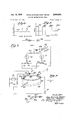
- Figure 1 is an exaggerated illustrative view of a vertical gyroscope with reference to the position of an aircraft in which it is mounted;
- Figure 2 is an illustrative view of the gyroscope action upon roll of the airplane
- Figure 3 is a perspective view of a vertical gyroscope, with a simplified form of slaving control
- Figure 4 is a fragmentary enlarged view of one of the slaving control pendulums illustrated in Fig. 3;
- Figure 5 is a view of a conventional slaving control circuit for apparatus of the character illustrated in Figure 3;
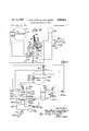
- Figure 6 is a chart illustrating a characteristic bearing friction or resistance to movement in the gyroscope mounting encountered during rotation of the gimbal mountings
- Figure 7 is a slaving or corrective restoring circuit embodying my invention.
- Figure 8 is a chart illustrative of the slaving torque or force pulsations provided by my invention.
- Figure 9 is a partial schematic view of a slaving system embodying another and more generally used type of control pendulum for actuating the slaving system as a function of a movement affecting the gyroscope;
- Figure 10 is a schematic view of a slaving system incorporating a control device for minimizing contact difliculties and obviating inoperativeperiods of the slaving system;
- Figure 11 is a schematic view of a slaving system incorporating a still further improved system for overcoming contact difficulties
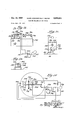
- Figure 12 is a side elevation, partly schematic, of a control device including periodically actuated magnetic means urging the movable control element toward the nearest of its two limiting contacting positions;
- Figure 13 is an end view of the device, looking from the left of Figure 12, with its associated circuit;
- Figure 14 is a sectional view of the device looking along the line 14-14;
- Figure 15 is a schematic plan view of an alternative control device
- Figure 16 is a schematic'plan view of still another control device with its associated circuit
- Figure 17 is a schematic plan view of yet another control device, with a different associated circuit
- Figure 18 is a vertical sectional view along the line 18-48 of Figure 17;
- Figure 19 is a schematic plan view of still another control device
- Figure 20 is a side elevational view of this same device, looking from the bottom of Figure 19;
- Figure 21 is a simplified perspective view of a directional gyroscope with its associated slaving controls.
- Figure 22 is acircuit diagram illustrating the use of my invention in connection with this form of gyroscope.
- gyroscopes mounted in such a manner that they are termed free gyroscopes, the mounting including gimbals enabling rotation about two axes mutually perpendicular to the axis of rotation of the gyroscope 'rotor.
- Such devices usually with high speed rotation of the rotor, are used in navigational instruments, to provide signals for automatic pilot systems, and in connection with other systems such as bomb sights, gun control equipment, and the like.
- a gyroscopic instrument of such a type maintains a fixed angular position with sufficient accuracy for the operational purposes only for a limited period of time.
- gravity does not coincide with the intersection of the three axes, and bearing friction, introduce influences affecting the gyroscope position as a result of changes of attitude of the craft in which it is mounted.
- some other devices must be used to provide a signal tending to correct or restore the gyroscope to the desired angle, and such a device together with its motor means and actuating system is generally termed a slaving system.
- the restoring or corrective force provided by the slaving system must exceed the maximum resistance to movement encountered, yet should preferably be kept as low as possible in order to avoid inaccuracies in position which otherwise would be introduced by overcompensation.
- simple pendulums may be used as the actuating device for the slaving system.
- the actuating force provided during operative periods may have an. amplitude easily able to overcome any transient peak resistance encountered, yet by properly spacing the periods of actuation the average force provided may be very substantially less, as for example of the order of a half, and only slightly exceeding the average resistance to movement provided by the gyroscope mounting.
- Figure 1 schematically illustrates a free gyrosco e of the vertical tvne, as one embodiment of a device with which my inventions may be used.
- a rotor 20 revolves at high speed. the drive means not being here illustrated in order to simplify the drawing.
- the axis 21 is mounted in a gimhal ring 22 carried by axis 23 mounted in bearings in another gimbal ring 24, this in turn being carried by an axis 25 mounted on standards 26a and 26b. So long as: the aircraft maintains straight and normal flight the rotor, if the gyroscope is perfectly balanced.
- FIGs 3, 4 and 5 illustrate a gyroscope in more conventional form, rather than illustratively only as in Figures 1 and 2, and the slaving or corrective mechanism for overcoming such precession.
- the gyroscope rotating element 30 is illustrated as the armature of the motor, with the housing 31 acting as the motor stator and as a gimbal ring mounted on the shaft 32.
- Motor means capable of supplying a desired torque or corrective restoring force is here illustrated as an electric motor 33 operative on the shaft 32, it being understood that the stator of this motor is mounted on the gimbal ring 34.
- This ring is in turn carried by the shaft 3d mounted in standards 36a and 36b.
- the standard 36a is also illustrated as carrying the casing of another motor means 37 adapted to apply a restoring torque to the shaft 35.
- the pendulum arrangement B is illustrated as comprising a freely movable pendulum member 38 swingable about an axis 39 carried by a pair of standards 40a and 40b.
- the end of the member 31% is movable between two limiting contact positions in contact with either of the fixed contact elements 41 or 42.
- the other pendulum system is similar except that its mounting is such as to cause its movable member to swing in a plane normal to the pendulum arrangement B just described.
- FIG. 7 a circuit is illustrated embodying my invention.
- this circuit I have broken the common return lead 50 from the motors 33 and 37 to the batteries 43 and 49, and completion of this common return is through the contacts 51a and 51!).
- a separate motor 52 is provided continuously rotating the cam 53 for moving the contact 51b and opening and closing the circuit. If the movable pendulum member 45 is in contact with fixed contact 47. the slaving torque or restoring force applied by the motor means 33 to the shaft 32 may then be as illustrated in Figure 8.
- spaced periods of application of is in engagement with one of the fin pulses of torque or restoring force, of an amplitude and duration greater than the maximum resistance to movement provided by friction if" the bearings, here identified as the force pulses 54a-d, are separated by periods of no force application, so that the resultant average restoring or corrective force may be considered to be of the the spacing between the force application pulses, as co mpared with their duration, determines the average force 55.
- a gyro-scope slaving system embodying a different type of pendulum having less dead or inactive range; that is, a type wherein sufficient contact separation is permitted to insure against shorting even if dirt collects or some pitting of the contacts occurs, yet wherein a lesser angle of movement of the gyroscope device than in the type of pendulum heretofore discussed results in contact being made.
- the gyroscope rotor 60 is again illustrated as mounted in a casing 61 carried by shaft 62 mounted in gimbals as heretofore illustrated, such "shaft being adapted to have corrective or slaving torque applied thereto by the motor means 63.
- a vertical shaft 6-4- has the movable pendulum member 65 pivoted thereon with a suitable low friction bearing, the contacts on the end of this pendulum member being adapted to engage fixed contacts and 67.
- substantial range of movement for the pendulum member 65 may be provided between the limiting positions provided by the fixed contacts, very small angular deviation of the 62. about the axis X results in engagement or contacting of the pendulum 'r'nember and one of the fixed. contacts, thus minimizing the inactive or dead zone of the pendulum device providing the slaving signal or control.
- a separate motor 68 continuously rotates a cam opening and closing contacts 7% and 70b; and when the pendulum member contacts, a circuit of the appropriate type is again completed from the battery '71 through the motor with the actuation being of the intermittent periodic or pulsating type by reason of the opening and closing of the contacts 70.
- current through the motor is in series with one of the resistors 72 and 73, with this series combination being in shunt with the other resistor; a very simple circuit is thus provided enabling reversal of torque in the motor from a single source of energy, as the cattery 71 illustrates.
- the slave motor 8i? 1s pot actuated directly from the contacts of the pendulum device, but through an intermediate device comprising a polarized relay actuated by the pendulum devicecontacts. Since the relay can be built to be quite sensitive, the current handled by the free swinging pendulum arrangement may thus be made very greatly less than that required by the restoring or slave motor means.
- the polarized relay comprises a closed core 81 having an arcuate portion over which a coil 82 is movable, the coil being mounted on the end of an arm 83 pivoted at 84.
- a permanent magnet 85 provides a predetermined permanent magnetic condition in the closed core, and the direction of current through the coil 82 (determined by the position of the pendulum member 75) determines the position taken by the coil on the polarized relay. That is, at one contacting position of the pendulum member current flows through the coil 82 in one direction from the battery 35, while in the other contacting position of the pendulum member 75 current flows through the coil in the opposite direction from the battery 86, a resistor 87 limiting the current to the desired value in each case.
- a toggle action for the arm 83 is provided by the use of an additional movable member 88 pivoted at 82 with a spring 90 providing an o-ver-center or toggle action bringing the upper end of the arm 83 into engagement with one or the other of the stops 91 and $2. .
- the arm 83 also carries a movable contact member 93 making engagement with one or the other of the fixed contacts 94- and 95.
- the circuit for the restoring motor 8b is completed through one or the other of these fixed contacts to one of the batteries 85 and 86; and intermittent or pulsating operation is again provided by the use of a separate motor 96 and a contacting disc 97 having a semicircular conductive portion 97a, so that the circuit is intermittently periodically completed and broken between the wiper elements 98a and 98b.
- this toggle action relay With this toggle action relay, the main current carrying contacts are always closed with substantial contact pressure, and when they are separated, such separation is quick and clean; and the pendulum operated contacts need carry only such current as is necessary to operate the relay.
- FIG. 11 Still another method of overcoming contact difficulties is shown in Figure 11. Fitting, corroding, and other contact point troubles occur substantially entirely as the result of opening of a circuit (with attendant arcing), rather than from closing of a pair of contacts.
- the circuit shown in Figure 11 causes the pendulum device merely to close relay means actuating the slaving motor, this relay means thereafter keeping the slaving motor circuit closed and avoiding any further current'carrying operation by the contacts of the pendulum device until such time as that device calls for an opposite movement of the slaving motor.
- the movable pendulum arm 23%) pivots about the shaft 231 as a result of deviations of the rotor housing 232, the contact member 233 at the end of the arm swinging between fixed contacts 234 and 235.
- Two multi-contact relays are provided, here identified in general as 240 and 250.
- the pendulum contact 233 has just previously engaged the fixed contact 235, and that this has resulted in the movable element 251 being raised by energization of the coil 252.
- the movable element 251 is provided with contact bars 25in, 251i) and 251C, these all being in their uppermost position as a result of the energization just mentioned.
- an actuating circuit for the slaving motor 265 is completed from a power source here indicated as the battery 261 through the fixed contacts 255a and 25512 and contact bar 2510, the current limiting resistor 262 and the contacts of the interrupter device 7.63 driven by the motor 264. It will be also noted that in this situation a holding circuit for the coil 252 of the relay 25% is completed through the lower contacts 244a and 244b, and the contact bar 241b, of the relay 240. In this condition of the system not only is the slaving motor actuated in a given direction in the desired'intermittent or periodic manner, but this actuation continues independently of whether or not the pendulum contact 233 remains in engagement with the fixed contact 235.
- the pendulum device no longer acts as a current carrying device, insofar as the slaving motor is concerned, and making and breaking between the contacts 233 and 235 not only does not aifect the operation of the slaving motor, but does not even result in any appreciable current flow through these contacts.
- a gyroscope casing 1.61 carries a shaft M2 on which is mounted a swingable pendulum arm M3 divided into sections for a purpose which will become apparent.
- the rigid back section has mounted thereon a leaf spring section MS which carrie an Outer portion 1%.
- a soft iron armature member 167 adapted to cooperate with the pole piece Tide of an electromagnet M9.
- the electromagnet is intermittently periodically actuated, as for example once each second, from the source illustrated as the battery .llrtl through Wipers Mia and llib adapted to have a circuit therebetween made and broken by the disc 112 continuously rotated by the motor 113.
- the electromagnet Jill? When the electromagnet Jill? is energized, it positively and strongly pulls down the outer portion 2% of the pendulum arm; and when the electromagnet is inactive the spring portion res positively and rapidly elevate the outer portion of the pendulum arm, breaking contact.
- a prism or pyramidal element 114 adapted to cooperate with another oppositely facing prism-like or pyramidal portion 115, as can be best seen in Figure 14. Swinging movement of the pendulum outer portion M6 is limited by the stop members 116 and 117; and downward movement of the portion 106 as the result of actuation of the electromagnet 109, dulum member is at all off-center, not only moves it downwardly but also outwardly to the limit of its movement in such regard through interaction of the sloping faces of the 115.
- the pend prism-like or pyramidal elements 114 and The end of the outer portion 106 carries a contact member 118 adapted to make contact with either of two fixed contacts 119 and 120 when the portion 106 is pulled downwardly.
- contact 118 is in engagement with fixed contact 120 current from the battery 121 flows through the resistor 122 and the slaving or restoring motor 123 in one direction; and when the movable contact 118 is in engagement with the fixed contact 19 current flows through the resistor 124 and the motor 123 in the opposite direction.
- resistor 124 and the motor 123 in the opposite direction.
- the pendulum device just described has the advantage of not only overcoming contacting difiiculties but also of automatically providing a pulsating actuation of the slaving motor 123.
- the spring portion 105 ensures a quick and positive separation of the contacts; and closing of either contact arrangement occurs only when the electromagnet 1699 is energized so that even if the pendulum member remains at one side at the limit of its swing (determined by a stop member, as 117) the circuit through the slaving motor is made and broken in accordance with the operation of the electromagnet 109.
- the pendulum member has been illustrated as fully free. However, the effect of random movements, particularly from vibration, can be minimized by providing a centering force tending to hold the swingable pendulum member in central position.
- the pendulum member 336 swingably mounted on the shaft 131 carried by the casing 132, is normally centered in the absence of a substantial deflecting force by the spring sections 133 and 134-, having their Outer ends fixed to posts 135 and 136.
- a movable contact element 137 is adapted to engage either of the fixed contacts 138 or 139; and positive engagement of the contacts when the arm is nearer one or the other is ensured by the provision of an electromagnet 14d having a yoke 141 of soft iron or the like cooperating with an armature member 142 of similar material.
- Current through the coil of the electromagnet is again provided intermittently by virtue of the cooperation of the continuously rotated disc 143 with the wiper arm and 14417 to alternately open and close a circuit from the battery 145.
- a circuit is intermittently periodically made and broken to the resistors 146 and 147 having the slaving motor M8 shunted thereacross.
- the presence of the spring centering means keeps vibration or other minor random effects from closing the slaving motor actuating contacts; but when a steady force due to angular change in attitude of the housing 132 brings the armature member 142 closer to one end of the yoke Mi, energization of the electromagnet quickly and positively swings the pendulum member toward such nearest contact and closes the circuit through one of the fixed contacts and 139.
- the centering force for the swingable pendulum member 15h mounted on the shaft 151 carried by the casing 152, is of a magnetic type which I prefer to the spring arrangement heretofore described.
- the pendulum member again carries a movable contact element 153 having its opposed contacting faces adapted to make engagement with one or the other of the fixed contacts 154 and 155.
- magnetic means here shown as a permanent magnet 161 movable with the pendulum member 150 and cooperating with an electromagnet.
- the electromagnet comprises the coil portion 163 and a yoke portion of soft iron or other suitable material; the leg portions 163a and 16317 of this yoke being adapted to cooperate with the permanent magnet 161 to provide the desired centering force.
- Current is supplied to the electromagnet coil 162 in an intermittent periodic manner from the source 157 through the contacts 164:: and 164b, these contacts 164 being periodically opened and closed by the cam 165 driven by the motor 160.
- a pendulum arm 171 is again shown as pivoted about the post 172 carried by the gyroscope casing 173; and the pendulum member carries a movable contact 174 adapted to make engagement with either of two fixed contacts 175 and 176.
- the outer end of the pendulum member 171 in this case is turned up to provide a vertically extending end portion 171a carrying a permanent magnet 176.
- This is again adapted to cooperate (to effect centering action on the pendulum member) with periodically created like poles in leg portions 177a and 1771; of a yoke member 177 carrying an electromagnet coil 178.
- Another portion 179 of permeable material, as soft iron, is provided to increase the amount of flux set up in the yoke 177 by energization of the coil.
- This energization is periodically effected from a suitable source of power, illustrated as the battery 180, through a circuit periodically completed through the wiper elements 181a and 18111 by the conductive portion 182a of a disc 182 rotated continuously by the motor 183.
- the slaving motor 170 is in this case illustrated as a motor of the eddy current type analogous to that used in the conventional alternating current watt meter; that is, a rotating disc 170a of conducting material is acted upon by the magnetic field created in coil portions 17% and 170s.
- a three-phase generator 184 provides the source of operative power in the case of this particular embodiment.
- One of the output connections of the three-phase generator is connected directly to the motor coil 170k by the lead 185; whereas the other two outputs of the generator are connected across a coil 186 having a center tap 186a.
- This center tap is connected through wiper members 187a and 187b, periodically connected through the conductive portion 188a of a disc 188 also rotated by the motor 183, to terminals of the coils 17017 and 1700.
- the other terminal of the coil 1700 is connected to the movable contact member 174 carried by the pendulum member; and the two fixed contacts 175 and 176 with which this movable contact cooperates are connected to opposite end portions of the coil 186.
- the current through coil a will either lead or lag the current through coil 17Gb; i. e., there will be a leading or lagging phase difference which will determine the direction of rotation of the motor disc 1700:.
- Figures 19 and 20 illustrate the use of magnetic forces for centering the pendulum and for increasing the contact pressure when a contact is made; but contrary to the arrangement shown in Figures 17 and 18, for example, centering is here effected when the electromagnet is deenergized and contact engagement is assisted when the electromagnet is energized, this opposite action resulting from the fact that the plane of the magnetic action is vertical in the device shown in these Figures 19 and 20, rather than horizontal as in the device shown in Figures 17 and 18.
- the gyroscope casing 301 has mounted on the top thereof a pendulum arm 302 pivotal about the vertical shaft 303. Near its center, as illustrated, the pendulum arm carries the movable contact members 304a and 3041); and these are adapted to make engagement with the fixed contacts 305a and 3051). Near its outer end the pendulum arm carries a vertical bar magnet 306 of the permanent type here indicated for illustrative purposes as having its north pole at the top and its south pole at the bottom.
- An electromagnet comprising a U-shaped soft iron armature 307 with a magnet coil 308 is fixedly mounted on the gyroscope casing.
- An additional soft iron member 309 cooperates with the U-shaped armature to improve the flux circuit.
- the coil i so wound and connected that when it is energized the upper end of the U-shaped core member 307 is north, and the lower end south (as identified in Figure 20), so that energization of the electromagnet tends to swing the pendulum away from the center, if it is the least bit off center, into engagement with one of the fixed contacts. 011 the other hand, when the coil 308 is deenergized, the soft iron member 307 loses its electrically induced poles and the bar magnet 306 tends to attract itself to and center it elf under this soft iron member.
- FIGS. 21 and 22 show in simplified form a gyroscope arrangement providing course 11 angle or heading, and a circuit for utilizing my invention in connection therewith.
- the mounting bracket 201 would be mounted in a suitable location in an aircraft, for example, and in turn would provide a mount ing for the shaft 2% carrying the gimbal ring 203 in which is mounted the shaft 294 carrying the gyroscope casing 23%, in turn providing a mounting for the shaft 286 on which the rotor element 207 revolves.
- a correcting or slaving motor 208 has its casing mounted on the supporting bracket 2M and its rotor connected to the shaft 292 to provide a suitable corrective torque; and another slaving motor 2ti9 has its casing mounted on the gimbal ring 2% and its rotor adapted to provide a corrective torque to the shaft 2%. While a pendulum arrangement of the type disclosed and illustrated earlier in this application could be used as the slaving signal source to control rotation of the casing 2% about the axis provided by the shaft course gyros generally operate satisfactorily if the casing 2% is merely maintained perpendicularly to the gimbal ring 2033.
- a simple slaving signal source frequently used for this purpose comprises a potentiometer arrangement having a resistance section 21d fixedly mounted on the gimbal ring 203, engaged by a movable contact member 211 carried by the shaft 284; so that any change in the relative position of the casing 295 and gimbal ring 203 results in movement of the contact arm 211 on the potentiometer resistance element 214).
- the potentiometer controls the action of the slaving motor 209.
- the slaving control for the other motor 208 is provided by another potentiometer arrangement here shown as controlled by a compass needle 212. While for simplicity of illustration this is shown as a simple compass mounted in direct association with the course gyroscope, it will be understood that in commercial practice a more satisfactorily operative compass (as a Sperry flux valve or a Bendix flux gate) might be used, and that it would normally be located in a wing or tail section not influenced by stray fields, with an appropriate telacontrol system to transmit information as to its position to the course gyroscope slaving system.
- a compass needle 212 While for simplicity of illustration this is shown as a simple compass mounted in direct association with the course gyroscope, it will be understood that in commercial practice a more satisfactorily operative compass (as a Sperry flux valve or a Bendix flux gate) might be used, and that it would normally be located in a wing or tail section not influenced by
- the compass needle 212 aligns itself (over average period) with the north magnetic pole, and its position controls the position of the shaft 213 on which are mounted wiper elements 214 and 215 providing the movable contacts of a pair of potentiometers having their fixed resistance elements 216 and 217 mounted on the shaft 2G2. Accordingly, variation in the relative positions (about a vertical axis) of the gimbal ring 203 and compass needle 212 will result in the creation of a corrective signal for the slaving system.
- a source of operating current is here illustrated as the two battery sections 218 and 219 having shunted thereacross not only the potentiometer resistance 210, but also the potentiometer resistances 216 and 2&7 in a parallel circuit arrangement with each other.
- a circuit for the slaving motor 269 is completed from the movable contact 211 through a pair of wiper elements 22th: and 22011, when connected, to the center point between the batteries 21S and 219; and circuit connection between these wiper elements is alternatively made and brolten by the conducting section 221a of a control disc 221 continuously rotated by the motor 222. Intermittent periodic pulses of operating current are thus supplied to the slaving motor 289 with all of the advantages of that system heretofore described whenever the movable contact 211 departs from center position on its cooperating potentiometer resistance element are.
- the other slaving motor 208 has its two terminals connected respectively to the movable contact elements 214 and 215 of the other potentiometer arrangements;
- the potentiometer resistance elements 216 and 217 thus provide in effect the four legs of a bridge circuit; and any change from central position of the movable contacts 214 and 215 results in pulses of operating current in suitable direction being supplied to the slaving motor 208.
- a slaving system for a gyroscope apparatus including: a movably mounted member movable over a range between two remote positions as a function of a movement affecting the gyroscope; means, including a spring actuated toggle arrangement which holds the member in the limiting position, for urging the member toward the nearest of said limiting positions; motor means for applying a restoring force to the gyroscope; and means for actuating the motor means in accordance with the position of the movable member.
- apparatus including: a movably mounted member movable over a range between two limiting positions as a function of a movement affecting the gyroscope; motor means for applying a restoring force to the gyroscope; means for actuating the motor means in accordance with the position of the movably mounted member; means associated with said movably mounted member and defining spaced north and south magnetic poles; magnetic means movable with the gyroscope; and means alternately energizing said magnetic means for reaction with said pole defining means to apply a centering force to the movably mounted member and allowing said magnetic means to have an inductive reaction with said pole defining means to assure movement of the movably mounted member to a limiting position toward which it is urged by the movement of the gyroscope.
- a movably mounted member movable over a range between two limiting positions as a function of a movement affectingthe gyroscope; motor means for applying a restoring force to the gyroscope; means for actuating the motor means in accordance with the position of the movably mounted member; and means for seriatim centering said movably mounted member notwithstanding the movement of the gyroscope and assuring its movement from an intermediate to a limiting position toward which it is urged by the movement of the gyroscope.
- a movably mounted member movable over a range between two limiting positions as a function of a movement affecting the gyroscope; motor means for applying a restoring force to the gyroscope; means for actuating the motor means in accordance with the position of the movably mounted member; electromagnetic means associated with said movably mounted member for centering the movably mounted member and for assisting its movement from an intermediate to a limiting position; and means for periodically energizing said electromagnetic means.
Landscapes
- Engineering & Computer Science (AREA)
- Radar, Positioning & Navigation (AREA)
- Remote Sensing (AREA)
- Automation & Control Theory (AREA)
- Physics & Mathematics (AREA)
- General Physics & Mathematics (AREA)
- Connection Of Motors, Electrical Generators, Mechanical Devices, And The Like (AREA)
Description
Jan- 13, 1 HANS-JOACHIM KURT MEYER 2,358,024
SLAVING MECHANISM FOR GYROS Filed Sept. 28. 1954 6 Sheets-Sheet 1 I Irz/n i07 fla 551711 [Di Jan. 13, 1959 HANS-JOACHIM KURT MEYER 4 SLAVING MECHANISM FOR GYROS Filed Sept. 28. 1954 6 Sheets-Sheet 2 FOR 06 v FR 1 0770A:
a Izflzz l ar has-fish: 6711-277 0 m i; 706 jaw? 10 flrnqg Jan. 13, 1959 HANS-JOACHIM KURT MEYER 2,853,024
SLAVING MECHANISM FOR GYROS V Filed Sept. 28. 1954 6 Sheets-Sheet 3 rugs- Jan. 13, 1959 HANS-JOACHIM KURT MEYER 2,868,024
SLAVING MECHANISM F OR GYROS Filed Sept. 28, 1954 6 Sheets-Sheet 5 Jan. 13, 1959 HANS-JOACHIM KURT IVIEYYER 2,853,024
SLAVING MECHANISM FOR GYROS Filed Sept. 28. 1954 6 Sheets-Sheet 6 I .ZZw/zz for 2154i; [or 1% er 6% United States Patent G SLAVING MECHANISM FOR GYROS Hans-Joachim Kurt Meyer, Lemont, 111., assignor to Ampatco Laboratories Corporation, a corporation of Delaware This invention relates to slaving mechanisms for gyroscopes, particularly for gyroscopes of the free type mounted in gimbals for rotation about three axes.
One feature of this invention is that it provides an improved slaving or correcting system for mechanical stabilizers involving a free gyroscope, as artificial horizon systems and directional gyroscopes; another feature of this invention is that it provides an improved slaving system for free gyroscopes used as a reference device in any system subject to variations in attitude, as an autopilot system of an aircraft; a further feature of this invention is that it provides a slaving or correcting force only slightly greater than the average resistance to movement in the gyroscope mountings, thus minimizing the rate of corrective action and maintaining the gyroscope nearer the desired attitude, while at the same time being capable of overcoming temporary high resistances to movement in the mounting; yet another feature of this invention is that the slaving torque or force is actuated intermittently and periodically, to provide sufficient force to overcome the maximum resistance encountered and yet provide an average restoring or correcting force substantially less than that required to overcome such maximum resistance so that the rate of movement of the correcting force need be only a small fraction of a degree per minute greater than the drift; still afurther feature of this invention is the provision of means for obviating any intermediate ineffective positions of the control device when no slaving or corrective restoring forces would otherwise be applied; and a further feature of this invention is the provision of intermittently magnetically actuated means for causing a movable control member to assume one or the other of two limiting contacting positions to improve contact pressure and slaving operation.
Other features and advantages of this invention will be apparent from the following specification and drawings, in which:
Figure 1 is an exaggerated illustrative view of a vertical gyroscope with reference to the position of an aircraft in which it is mounted;
Figure 2 is an illustrative view of the gyroscope action upon roll of the airplane;
Figure 3 is a perspective view of a vertical gyroscope, with a simplified form of slaving control;
Figure 4 is a fragmentary enlarged view of one of the slaving control pendulums illustrated in Fig. 3;
Figure 5 is a view of a conventional slaving control circuit for apparatus of the character illustrated in Figure 3;
Figure 6 is a chart illustrating a characteristic bearing friction or resistance to movement in the gyroscope mounting encountered during rotation of the gimbal mountings;
Figure 7 is a slaving or corrective restoring circuit embodying my invention;
Figure 8 is a chart illustrative of the slaving torque or force pulsations provided by my invention;
Figure 9 is a partial schematic view of a slaving system embodying another and more generally used type of control pendulum for actuating the slaving system as a function of a movement affecting the gyroscope;
Figure 10 is a schematic view of a slaving system incorporating a control device for minimizing contact difliculties and obviating inoperativeperiods of the slaving system;
Figure 11 is a schematic view of a slaving system incorporating a still further improved system for overcoming contact difficulties;
Figure 12 is a side elevation, partly schematic, of a control device including periodically actuated magnetic means urging the movable control element toward the nearest of its two limiting contacting positions;
Figure 13 is an end view of the device, looking from the left of Figure 12, with its associated circuit;
Figure 14 is a sectional view of the device looking along the line 14-14;
Figure 15 is a schematic plan view of an alternative control device;
Figure 16 is a schematic'plan view of still another control device with its associated circuit;
Figure 17 is a schematic plan view of yet another control device, with a different associated circuit;
Figure 18 is a vertical sectional view along the line 18-48 of Figure 17;
Figure 19 is a schematic plan view of still another control device;
Figure 20 is a side elevational view of this same device, looking from the bottom of Figure 19;
Figure 21 is a simplified perspective view of a directional gyroscope with its associated slaving controls; and
Figure 22 is acircuit diagram illustrating the use of my invention in connection with this form of gyroscope.
Various devices on moving vehicles, as airplanes and ships, must be mounted in such a way that they do not participate in changes'of attitude of the craft, as pitching or rolling thereof, turns, and the like. This is usually accomplished by the use of gyroscopes mounted in such a manner that they are termed free gyroscopes, the mounting including gimbals enabling rotation about two axes mutually perpendicular to the axis of rotation of the gyroscope 'rotor. Such devices, usually with high speed rotation of the rotor, are used in navigational instruments, to provide signals for automatic pilot systems, and in connection with other systems such as bomb sights, gun control equipment, and the like.
A gyroscopic instrument of such a type, however, maintains a fixed angular position with sufficient accuracy for the operational purposes only for a limited period of time. gravity does not coincide with the intersection of the three axes, and bearing friction, introduce influences affecting the gyroscope position as a result of changes of attitude of the craft in which it is mounted. Accordingly, some other devices must be used to provide a signal tending to correct or restore the gyroscope to the desired angle, and such a device together with its motor means and actuating system is generally termed a slaving system.
The restoring or corrective force provided by the slaving system must exceed the maximum resistance to movement encountered, yet should preferably be kept as low as possible in order to avoid inaccuracies in position which otherwise would be introduced by overcompensation. In a vertical gyro, for example, simple pendulums may be used as the actuating device for the slaving system. While the random motions of an aircraft will over a relatively long period average out, during any given short interval of time the pendulum will be undesirably affected by any attitude of the aircraft other than straight and normal flight, and accordingly it is desirable to keep the Mechanical unbalance such that the center of v average restoring or corrective force only slightly higher than the average resistance to movement in the gyroscope mounting in order to minimize undesired changes in angle of the gyroscope. In a-well designed gyroscope of the type used in an auto-pilot system, for example, precession or changes in attitude due to bearing friction or similar factors seldom exceeds 1 per minute. It will thus be obvious that the corrective force provided by the slaving system will operate most advantageously if its rate of correction only very slightly exceeds this figure.
In systems heretofore used, however, the necessity of overcoming peak resistances to movement in the mountings, even though such relatively high resistance might be temporary and brief, has resulted in the provision of a slaving or restoring force two or three times the average resistance to movement. Although a ball bearing of quality or precision characteristics has a very low average resistance to movement, differences due to minute irregularities sometimes accumulate during movement of the balls and result in a brief peak resistance to movement which may be double or triple the average resistance, as is illustrated in Figure 6.
I have overcome this problem, in the system disclosed here, by providing a pulsating or intermittently and periodically actuated slaving force. By utilizing such periodic actuation, the actuating force provided during operative periods may have an. amplitude easily able to overcome any transient peak resistance encountered, yet by properly spacing the periods of actuation the average force provided may be very substantially less, as for example of the order of a half, and only slightly exceeding the average resistance to movement provided by the gyroscope mounting.
In addition, the use of a freely movable pendulum type of device for providing the slaving si nal sometimes results in extremely light and unsatisfactory contact pressure. and undesired arcing where the movable pendulum member tends to swing away from a fixed contact. but witho t doing so quickly and cleanly. I have overcome this difficulty by using in the slaving system, either as the si nal source or as a separate device in the svstem. a de-- vice for insuring maintenance of good contact between a. central. movable member and one or the other of twolimiting contact positions between which it moves. I' prefer to. do this by providing an intermittently actuated arran ement'for positively moving the movable member toward and into firm en agement with the nearest contact and for re eating this at periodic intervals with the intervening periods enabling the movable member to assume a. new relationship if the attitude of the craft in: wh ch it is mounted has changed.
Referring now more particularly to the drawings. Figure 1 schematically illustrates a free gyrosco e of the vertical tvne, as one embodiment of a device with which my inventions may be used. in relation to an air lane illustrated in small size in order that the relative positions may be easily understood. A rotor 20 revolves at high speed. the drive means not being here illustrated in order to simplify the drawing. The axis 21 is mounted in a gimhal ring 22 carried by axis 23 mounted in bearings in another gimbal ring 24, this in turn being carried by an axis 25 mounted on standards 26a and 26b. So long as: the aircraft maintains straight and normal flight the rotor, if the gyroscope is perfectly balanced. would maintain the position illustrated with the axes X, Y, Z all being' mutually perpendicular. If the plane rolls, however, as' illustrated in Figure 2, bearing resistance in the bearings: 27a and 27b applies a force tending to rotate the gimbal ring 24 about the axis X. While this is resisted by the gyroscope, the force thus applied results in precession of' the gyroscope axis 21 from the original position Z to some new position Z, for example, the amount of precession shown being excessive for illustrative purposes. Similarly, if the plane climbed, dived or looped, friction in the bearings 28a and 28!) would result in precession about the axis X rather than about the axis Y, as previously illustrated, tending to make the gyroscope axis Z move to the left or right of its correct position.
Figures 3, 4 and 5 illustrate a gyroscope in more conventional form, rather than illustratively only as in Figures 1 and 2, and the slaving or corrective mechanism for overcoming such precession. Referring first to Figure 3, the gyroscope rotating element 30 is illustrated as the armature of the motor, with the housing 31 acting as the motor stator and as a gimbal ring mounted on the shaft 32. Motor means capable of supplying a desired torque or corrective restoring force is here illustrated as an electric motor 33 operative on the shaft 32, it being understood that the stator of this motor is mounted on the gimbal ring 34. This ring is in turn carried by the shaft 3d mounted in standards 36a and 36b. The standard 36a is also illustrated as carrying the casing of another motor means 37 adapted to apply a restoring torque to the shaft 35.
v Mounted on the casing 31 are a pair of simple pendulum arrangements identified in general as A and B, the pendulums or movable elements of these arrangements swinging in planes at right angles to each other. Referring more particularly to Figure 4, the pendulum arrangement B is illustrated as comprising a freely movable pendulum member 38 swingable about an axis 39 carried by a pair of standards 40a and 40b. The end of the member 31% is movable between two limiting contact positions in contact with either of the fixed contact elements 41 or 42. The other pendulum system is similar except that its mounting is such as to cause its movable member to swing in a plane normal to the pendulum arrangement B just described.
Referring now more particularly to the circuit diagram comprising Figure 5, it will be seen that if the pendulum element 38 swings into engagement with the contact 41, current from the power source, illustrated as battery 43, suitably controlled as by the resistor 44, will flow through the motor 37 and provide a desired corrective restoring force in appropriate direction to the shaft 35. If the movable pendulum elements swing into contact with the contact 42, on the other hand, current from the source illustrated as battery 49 will flow in the opposite direction through the motor 3 7, thus applying opposite torque or restoring force to the shaft 35. Similarly, if the other movable pendulum element 45 swings into engagement with the contact 46, current fill flow from the battery 4-3 through the resistor 48 and motor 33 to apply a restoring torque in suitable direction to the shaft 32, with the opposite torque being provided if the contact .7 is contacted.
While the bearing friction of the mounting bearings normally provides a given average resistance to movement, occasionally there are brief periods of greatly increased resistance during rotation, as illustrated in Figure 6. Because of this my invention contemplates the use of a restoring force or torque exceeding the maximum resistance to movement to be encountered, but applied inter mittently or periodically.
With the previously described general system understood, and referring now more particularly to Figure 7. a circuit is illustrated embodying my invention. in this circuit I have broken the common return lead 50 from the motors 33 and 37 to the batteries 43 and 49, and completion of this common return is through the contacts 51a and 51!). In order to open and close these and intermittently periodically actuate the motors upon closure of a. movable pendulum member with one of its cooperating fixed contacts, a separate motor 52 is provided continuously rotating the cam 53 for moving the contact 51b and opening and closing the circuit. If the movable pendulum member 45 is in contact with fixed contact 47. the slaving torque or restoring force applied by the motor means 33 to the shaft 32 may then be as illustrated in Figure 8. That is, spaced periods of application of is in engagement with one of the fin pulses of torque or restoring force, of an amplitude and duration greater than the maximum resistance to movement provided by friction if" the bearings, here identified as the force pulses 54a-d, are separated by periods of no force application, so that the resultant average restoring or corrective force may be considered to be of the the spacing between the force application pulses, as co mpared with their duration, determines the average force 55. 'It will thus be apparent that by suitable design of the cam 53 the average restoring force applied can be made to only slightly exceed the average frictional resistance encountered, while at the same time the amplitude of the pulse actuations exceeds the maximum resistance to be encountered and insures the desired movement when the slaving system is actuated by either of the pendulum members.
Referring to Figure 9, comprising only a partial view, a gyro-scope slaving system is shown embodying a different type of pendulum having less dead or inactive range; that is, a type wherein sufficient contact separation is permitted to insure against shorting even if dirt collects or some pitting of the contacts occurs, yet wherein a lesser angle of movement of the gyroscope device than in the type of pendulum heretofore discussed results in contact being made. Here the gyroscope rotor 60 is again illustrated as mounted in a casing 61 carried by shaft 62 mounted in gimbals as heretofore illustrated, such "shaft being adapted to have corrective or slaving torque applied thereto by the motor means 63. In this case a vertical shaft 6-4- has the movable pendulum member 65 pivoted thereon with a suitable low friction bearing, the contacts on the end of this pendulum member being adapted to engage fixed contacts and 67. Even though substantial range of movement for the pendulum member 65 may be provided between the limiting positions provided by the fixed contacts, very small angular deviation of the 62. about the axis X results in engagement or contacting of the pendulum 'r'nember and one of the fixed. contacts, thus minimizing the inactive or dead zone of the pendulum device providing the slaving signal or control. A separate motor 68 continuously rotates a cam opening and closing contacts 7% and 70b; and when the pendulum member contacts, a circuit of the appropriate type is again completed from the battery '71 through the motor with the actuation being of the intermittent periodic or pulsating type by reason of the opening and closing of the contacts 70. lo the form of circuit shown in this figure, current through the motor is in series with one of the resistors 72 and 73, with this series combination being in shunt with the other resistor; a very simple circuit is thus provided enabling reversal of torque in the motor from a single source of energy, as the cattery 71 illustrates.
Where the motor means providing a slaving torque requires any appreciable power, the free pendulum arrangements have the disadvantage of trying to handle "such current with what may be extremely light contact pressure. This results not only in a lack of a definite current value, and thus an unr sired variation in the slaving torque, but also in pitting 5 ad burning difiiculties at the contacts. One arrangement for overcoming these problems is illustrated in Figure 10.
in this system a movable pendulum a m 75, pivoted about the shaft 76 on the rotor housing =1 again swings between fixed contacts 78 and 75 in accordance with the angular position of the housing 77.
In this arrangement, however, the slave motor 8i? 1s pot actuated directly from the contacts of the pendulum device, but through an intermediate device comprising a polarized relay actuated by the pendulum devicecontacts. Since the relay can be built to be quite sensitive, the current handled by the free swinging pendulum arrangement may thus be made very greatly less than that required by the restoring or slave motor means.
The polarized relay comprises a closed core 81 having an arcuate portion over which a coil 82 is movable, the coil being mounted on the end of an arm 83 pivoted at 84. A permanent magnet 85 provides a predetermined permanent magnetic condition in the closed core, and the direction of current through the coil 82 (determined by the position of the pendulum member 75) determines the position taken by the coil on the polarized relay. That is, at one contacting position of the pendulum member current flows through the coil 82 in one direction from the battery 35, while in the other contacting position of the pendulum member 75 current flows through the coil in the opposite direction from the battery 86, a resistor 87 limiting the current to the desired value in each case. A toggle action for the arm 83 is provided by the use of an additional movable member 88 pivoted at 82 with a spring 90 providing an o-ver-center or toggle action bringing the upper end of the arm 83 into engagement with one or the other of the stops 91 and $2. .The arm 83 also carries a movable contact member 93 making engagement with one or the other of the fixed contacts 94- and 95. The circuit for the restoring motor 8b is completed through one or the other of these fixed contacts to one of the batteries 85 and 86; and intermittent or pulsating operation is again provided by the use of a separate motor 96 and a contacting disc 97 having a semicircular conductive portion 97a, so that the circuit is intermittently periodically completed and broken between the wiper elements 98a and 98b. With this toggle action relay, the main current carrying contacts are always closed with substantial contact pressure, and when they are separated, such separation is quick and clean; and the pendulum operated contacts need carry only such current as is necessary to operate the relay.
Still another method of overcoming contact difficulties is shown in Figure 11. Fitting, corroding, and other contact point troubles occur substantially entirely as the result of opening of a circuit (with attendant arcing), rather than from closing of a pair of contacts. The circuit shown in Figure 11 causes the pendulum device merely to close relay means actuating the slaving motor, this relay means thereafter keeping the slaving motor circuit closed and avoiding any further current'carrying operation by the contacts of the pendulum device until such time as that device calls for an opposite movement of the slaving motor.
Referring now more particularly to the arrangement illustrated in Figure 11, the movable pendulum arm 23%) pivots about the shaft 231 as a result of deviations of the rotor housing 232, the contact member 233 at the end of the arm swinging between fixed contacts 234 and 235. Two multi-contact relays are provided, here identified in general as 240 and 250. In the circuit diagram as illustrated, it Will be assumed that the pendulum contact 233 has just previously engaged the fixed contact 235, and that this has resulted in the movable element 251 being raised by energization of the coil 252. The movable element 251 is provided with contact bars 25in, 251i) and 251C, these all being in their uppermost position as a result of the energization just mentioned. Under these conditions an actuating circuit for the slaving motor 265 is completed from a power source here indicated as the battery 261 through the fixed contacts 255a and 25512 and contact bar 2510, the current limiting resistor 262 and the contacts of the interrupter device 7.63 driven by the motor 264. It will be also noted that in this situation a holding circuit for the coil 252 of the relay 25% is completed through the lower contacts 244a and 244b, and the contact bar 241b, of the relay 240. In this condition of the system not only is the slaving motor actuated in a given direction in the desired'intermittent or periodic manner, but this actuation continues independently of whether or not the pendulum contact 233 remains in engagement with the fixed contact 235. Once this has energized the relay 25h the pendulum device no longer acts as a current carrying device, insofar as the slaving motor is concerned, and making and breaking between the contacts 233 and 235 not only does not aifect the operation of the slaving motor, but does not even result in any appreciable current flow through these contacts.
When the pendulum device swings over as a result of change in attitude of the aircraft, so that the pend contact 2.33 engage the fixed contact 234, the coil of relay Edi is ener ized from the supply source here indicated diagrammatically as the battery 2.66. Energization of this relay lifts its movable element ildl and breaks the holding circuit provided by the Contact bar 24-11), resulting in the relay 25h dropping out. This results in contact bar 2351b engaging fixed contacts 254a and 254!) and engages contacts 256a and 256b. This latter engagement results in current from the source here diagrammatically indicated. as a battery 267 actuating the slaving motor in the opposite direction from that of Loo its previous energization, the circuit again being through the limiting resistor 262 and the contacts of the interrupting device 263. At the same time a holding circuit is provided for the relay 2% through the contacts 243a and 24312 and the contact bar Z lla in that relay, and the contacts 254a and 1254b and the contact bar 25% in the relay 250. The system is again in equilibrium with the relays maintaining energization of the slaving motor 265 regardless of the relationship between the contacts 233 and 234 in the pendulum device, until such time as contact may again engage contact 235, whereupon the initial situation of the system as illustrated in Figure 11 will be resumed.
Another and preferred arrangement for overcoming contact difiiculties and random action of the pendulum (due to vibration and other effects) is illustrated in Figures 12, 13 and 14. Referring now to these figures, a gyroscope casing 1.61 carries a shaft M2 on which is mounted a swingable pendulum arm M3 divided into sections for a purpose which will become apparent. The rigid back section has mounted thereon a leaf spring section MS which carrie an Outer portion 1%. On the underside of this outer section we is mounted a soft iron armature member 167 adapted to cooperate with the pole piece Tide of an electromagnet M9. The electromagnet is intermittently periodically actuated, as for example once each second, from the source illustrated as the battery .llrtl through Wipers Mia and llib adapted to have a circuit therebetween made and broken by the disc 112 continuously rotated by the motor 113. When the electromagnet Jill? is energized, it positively and strongly pulls down the outer portion 2% of the pendulum arm; and when the electromagnet is inactive the spring portion res positively and rapidly elevate the outer portion of the pendulum arm, breaking contact.
Near the center of the outer portion 106 of the pendulum arm is a prism or pyramidal element 114 adapted to cooperate with another oppositely facing prism-like or pyramidal portion 115, as can be best seen in Figure 14. Swinging movement of the pendulum outer portion M6 is limited by the stop members 116 and 117; and downward movement of the portion 106 as the result of actuation of the electromagnet 109, dulum member is at all off-center, not only moves it downwardly but also outwardly to the limit of its movement in such regard through interaction of the sloping faces of the 115.
if the pend prism-like or pyramidal elements 114 and The end of the outer portion 106 carries a contact member 118 adapted to make contact with either of two fixed contacts 119 and 120 when the portion 106 is pulled downwardly. When contact 118 is in engagement with fixed contact 120 current from the battery 121 flows through the resistor 122 and the slaving or restoring motor 123 in one direction; and when the movable contact 118 is in engagement with the fixed contact 19 current flows through the resistor 124 and the motor 123 in the opposite direction. In each case there is, of course, also a shunting circuit through the other resistor; but this merely affects the amount of current drawn and not the operation of the slaving motor.
The pendulum device just described has the advantage of not only overcoming contacting difiiculties but also of automatically providing a pulsating actuation of the slaving motor 123. When the electromagnet 109 is inoperative, the spring portion 105 ensures a quick and positive separation of the contacts; and closing of either contact arrangement occurs only when the electromagnet 1699 is energized so that even if the pendulum member remains at one side at the limit of its swing (determined by a stop member, as 117) the circuit through the slaving motor is made and broken in accordance with the operation of the electromagnet 109.
In the pendulum actuating arrangements as heretofore described, the pendulum member has been illustrated as fully free. However, the effect of random movements, particularly from vibration, can be minimized by providing a centering force tending to hold the swingable pendulum member in central position. In Figure 15 the pendulum member 336, swingably mounted on the shaft 131 carried by the casing 132, is normally centered in the absence of a substantial deflecting force by the spring sections 133 and 134-, having their Outer ends fixed to posts 135 and 136. A movable contact element 137 is adapted to engage either of the fixed contacts 138 or 139; and positive engagement of the contacts when the arm is nearer one or the other is ensured by the provision of an electromagnet 14d having a yoke 141 of soft iron or the like cooperating with an armature member 142 of similar material. Current through the coil of the electromagnet is again provided intermittently by virtue of the cooperation of the continuously rotated disc 143 with the wiper arm and 14417 to alternately open and close a circuit from the battery 145. At the same time a circuit is intermittently periodically made and broken to the resistors 146 and 147 having the slaving motor M8 shunted thereacross.
The presence of the spring centering means keeps vibration or other minor random effects from closing the slaving motor actuating contacts; but when a steady force due to angular change in attitude of the housing 132 brings the armature member 142 closer to one end of the yoke Mi, energization of the electromagnet quickly and positively swings the pendulum member toward such nearest contact and closes the circuit through one of the fixed contacts and 139. Even if a strong angular force, such as caused by a sharp turn or a roll of the airplane, causes continuous engagement of the movable contact element 137 with one of the fixed contacts, a pulsating slaving torque is still provided by the opening and closing of the motor actuating circuit through rotation of the disc In the device shown in Figure 16 the centering force for the swingable pendulum member 15h, mounted on the shaft 151 carried by the casing 152, is of a magnetic type which I prefer to the spring arrangement heretofore described. The pendulum member again carries a movable contact element 153 having its opposed contacting faces adapted to make engagement with one or the other of the fixed contacts 154 and 155. When either such contact is made a circuit for the slaving or restoring motor 156 is completed from the battery 157 or other suitable source of power through the intermittently opened and closed contacts 158a and 158b, the periodic interruption of these contacts being affected by the cam 159 driven by the motor 160. A pulsating slaving torque of the desired character is thus again provided by this device.
However, normal periodic centering is provided by magnetic means here shown as a permanent magnet 161 movable with the pendulum member 150 and cooperating with an electromagnet. The electromagnet comprises the coil portion 163 and a yoke portion of soft iron or other suitable material; the leg portions 163a and 16317 of this yoke being adapted to cooperate with the permanent magnet 161 to provide the desired centering force. Current is supplied to the electromagnet coil 162 in an intermittent periodic manner from the source 157 through the contacts 164:: and 164b, these contacts 164 being periodically opened and closed by the cam 165 driven by the motor 160. When the circuit to the electromagnet is completed, the direction of the coil windings and current flow are so arranged that poles similar to the adjacent permanent magnet poles are created in the leg portions 163a and 163b. The repelling interaction between the adjacent like poles provides a periodic force tending to center the pendulum arm 150, so that it is only in the periods when no centering force is being provided that the pendulum arm swings over and closes the circuit with one of the fixed contacts 154 or 155.
Referring now to Figures 17 and 18, a circuit is shown utilizing magnetic centering of the pendulum arm but differing from embodiments heretofore described by reason of utilizing an alternating current supply for the slaving or restoring motor 170. A pendulum arm 171 is again shown as pivoted about the post 172 carried by the gyroscope casing 173; and the pendulum member carries a movable contact 174 adapted to make engagement with either of two fixed contacts 175 and 176. The outer end of the pendulum member 171 in this case is turned up to provide a vertically extending end portion 171a carrying a permanent magnet 176. This is again adapted to cooperate (to effect centering action on the pendulum member) with periodically created like poles in leg portions 177a and 1771; of a yoke member 177 carrying an electromagnet coil 178. Another portion 179 of permeable material, as soft iron, is provided to increase the amount of flux set up in the yoke 177 by energization of the coil. This energization is periodically effected from a suitable source of power, illustrated as the battery 180, through a circuit periodically completed through the wiper elements 181a and 18111 by the conductive portion 182a of a disc 182 rotated continuously by the motor 183. l
The slaving motor 170 is in this case illustrated as a motor of the eddy current type analogous to that used in the conventional alternating current watt meter; that is, a rotating disc 170a of conducting material is acted upon by the magnetic field created in coil portions 17% and 170s. A three-phase generator 184 provides the source of operative power in the case of this particular embodiment. One of the output connections of the three-phase generator is connected directly to the motor coil 170k by the lead 185; whereas the other two outputs of the generator are connected across a coil 186 having a center tap 186a. This center tap is connected through wiper members 187a and 187b, periodically connected through the conductive portion 188a of a disc 188 also rotated by the motor 183, to terminals of the coils 17017 and 1700. The other terminal of the coil 1700 is connected to the movable contact member 174 carried by the pendulum member; and the two fixed contacts 175 and 176 with which this movable contact cooperates are connected to opposite end portions of the coil 186. Depending upon which of the two fixed contacts is engaged by the movable contact 174, the current through coil a will either lead or lag the current through coil 17Gb; i. e., there will be a leading or lagging phase difference which will determine the direction of rotation of the motor disc 1700:.
Figures 19 and 20 illustrate the use of magnetic forces for centering the pendulum and for increasing the contact pressure when a contact is made; but contrary to the arrangement shown in Figures 17 and 18, for example, centering is here effected when the electromagnet is deenergized and contact engagement is assisted when the electromagnet is energized, this opposite action resulting from the fact that the plane of the magnetic action is vertical in the device shown in these Figures 19 and 20, rather than horizontal as in the device shown in Figures 17 and 18.
'Referring now more particularly to Figures 19 and 20, the gyroscope casing 301 has mounted on the top thereof a pendulum arm 302 pivotal about the vertical shaft 303. Near its center, as illustrated, the pendulum arm carries the movable contact members 304a and 3041); and these are adapted to make engagement with the fixed contacts 305a and 3051). Near its outer end the pendulum arm carries a vertical bar magnet 306 of the permanent type here indicated for illustrative purposes as having its north pole at the top and its south pole at the bottom. An electromagnet comprising a U-shaped soft iron armature 307 with a magnet coil 308 is fixedly mounted on the gyroscope casing. An additional soft iron member 309 cooperates with the U-shaped armature to improve the flux circuit. The coil i so wound and connected that when it is energized the upper end of the U-shaped core member 307 is north, and the lower end south (as identified in Figure 20), so that energization of the electromagnet tends to swing the pendulum away from the center, if it is the least bit off center, into engagement with one of the fixed contacts. 011 the other hand, when the coil 308 is deenergized, the soft iron member 307 loses its electrically induced poles and the bar magnet 306 tends to attract itself to and center it elf under this soft iron member. It will be apparent that periodic energization and deenergization of the coil 308 of the electromagnet will thus result in both periodic centering of the pendulum member, and in moving the pendulum member to and holding it in good engagement (for a brief period) with one of the contact members when the gyroscope casing is tilted from the vertical axis.
It will be understood that where the magnetic centering is used the shape of the electromagnet and permanent magnet may be interchanged without change in the desired operation. Moreover, the types of magnetic centering illustrated in Figures 16, 17 and 18 may, if desired, be combined in the same device with electrom gnetic means for further increasing contact pressure beyond that effected by the permanent magnet, as means of the type illustrated in Figure 15, it then being necessary to have the centering electromagnet arrangement and the contact pressure increasing electromagnet arrangement operated alternately.
The provision of a periodically actuated magnetic centering force has a tendency to make the pendulum oscillate. If natural damping due to air friction and friction about the mounting post is insufficient to insure a rapid dying out of such oscillations after each centering action, additional damping means of any suitable type may be provided; for example, copper shorting rings may be placed around the leg portions of the electromagnet yoke to provide a magnetic damping action in the event of such oscillation.
While my inventions have heretofore been described in connection with a vertical gyroscope, as a gyroscope providing an artificial horizon, it is to be understood that they are equally adapted for use in any type of free gyroscope. For example, Figures 21 and 22 show in simplified form a gyroscope arrangement providing course 11 angle or heading, and a circuit for utilizing my invention in connection therewith.
Referring now ot Figure 21, a simple or basic form of course gyroscope is illustrated. The mounting bracket 201 would be mounted in a suitable location in an aircraft, for example, and in turn would provide a mount ing for the shaft 2% carrying the gimbal ring 203 in which is mounted the shaft 294 carrying the gyroscope casing 23%, in turn providing a mounting for the shaft 286 on which the rotor element 207 revolves. A correcting or slaving motor 208 has its casing mounted on the supporting bracket 2M and its rotor connected to the shaft 292 to provide a suitable corrective torque; and another slaving motor 2ti9 has its casing mounted on the gimbal ring 2% and its rotor adapted to provide a corrective torque to the shaft 2%. While a pendulum arrangement of the type disclosed and illustrated earlier in this application could be used as the slaving signal source to control rotation of the casing 2% about the axis provided by the shaft course gyros generally operate satisfactorily if the casing 2% is merely maintained perpendicularly to the gimbal ring 2033. Accordingly, a simple slaving signal source frequently used for this purpose comprises a potentiometer arrangement having a resistance section 21d fixedly mounted on the gimbal ring 203, engaged by a movable contact member 211 carried by the shaft 284; so that any change in the relative position of the casing 295 and gimbal ring 203 results in movement of the contact arm 211 on the potentiometer resistance element 214). The potentiometer, as will be more apparent from the circuit diagram, controls the action of the slaving motor 209.
The slaving control for the other motor 208 is provided by another potentiometer arrangement here shown as controlled by a compass needle 212. While for simplicity of illustration this is shown as a simple compass mounted in direct association with the course gyroscope, it will be understood that in commercial practice a more satisfactorily operative compass (as a Sperry flux valve or a Bendix flux gate) might be used, and that it would normally be located in a wing or tail section not influenced by stray fields, with an appropriate telacontrol system to transmit information as to its position to the course gyroscope slaving system. In the form shown here it will be assumed that the compass needle 212 aligns itself (over average period) with the north magnetic pole, and its position controls the position of the shaft 213 on which are mounted wiper elements 214 and 215 providing the movable contacts of a pair of potentiometers having their fixed resistance elements 216 and 217 mounted on the shaft 2G2. Accordingly, variation in the relative positions (about a vertical axis) of the gimbal ring 203 and compass needle 212 will result in the creation of a corrective signal for the slaving system.
Referring now more particularly to the circuit diagram of Figure 22, a source of operating current is here illustrated as the two battery sections 218 and 219 having shunted thereacross not only the potentiometer resistance 210, but also the potentiometer resistances 216 and 2&7 in a parallel circuit arrangement with each other. A circuit for the slaving motor 269 is completed from the movable contact 211 through a pair of wiper elements 22th: and 22011, when connected, to the center point between the batteries 21S and 219; and circuit connection between these wiper elements is alternatively made and brolten by the conducting section 221a of a control disc 221 continuously rotated by the motor 222. Intermittent periodic pulses of operating current are thus supplied to the slaving motor 289 with all of the advantages of that system heretofore described whenever the movable contact 211 departs from center position on its cooperating potentiometer resistance element are.
The other slaving motor 208 has its two terminals connected respectively to the movable contact elements 214 and 215 of the other potentiometer arrangements;
and the resistance elements 216 and 217, in parallel, are connected across the batteries 218 and 219 through the .Wiper elements 223a and 2232b adapted to have circuit connections therebetween alternately made and broken by the conducting section 224a of the disc 224 also rotated by the motor 222. The potentiometer resistance elements 216 and 217 thus provide in effect the four legs of a bridge circuit; and any change from central position of the movable contacts 214 and 215 results in pulses of operating current in suitable direction being supplied to the slaving motor 208.
While I have shown and described certain embodiments of my invention, it is to be understood that it is capable of many modifications. Changes, therefore, in the construction and arrangement may be made without departing from the spirit and scope of the invention as disclosed in the appended claims.
I claim:
1. In a slaving system for a gyroscope, apparatus including: a movably mounted member movable over a range between two remote positions as a function of a movement affecting the gyroscope; means, including a spring actuated toggle arrangement which holds the member in the limiting position, for urging the member toward the nearest of said limiting positions; motor means for applying a restoring force to the gyroscope; and means for actuating the motor means in accordance with the position of the movable member.
2. Apparatus of the character claimed in claim 1, wherein the means for urging the movably mounted member towards the nearest of said limiting positions is a magnetically actuated arrangement.
3. in a slaving system for a gyroscope, apparatus including: a movably mounted member movable over a range between two limiting positions as a function of a movement affecting the gyroscope; motor means for applying a restoring force to the gyroscope; means for actuating the motor means in accordance with the position of the movably mounted member; means associated with said movably mounted member and defining spaced north and south magnetic poles; magnetic means movable with the gyroscope; and means alternately energizing said magnetic means for reaction with said pole defining means to apply a centering force to the movably mounted member and allowing said magnetic means to have an inductive reaction with said pole defining means to assure movement of the movably mounted member to a limiting position toward which it is urged by the movement of the gyroscope.
4. In a slaving system for a gyroscope, apparatus including: a movably mounted member movable over a range between two limiting positions as a function of a movement affectingthe gyroscope; motor means for applying a restoring force to the gyroscope; means for actuating the motor means in accordance with the position of the movably mounted member; and means for seriatim centering said movably mounted member notwithstanding the movement of the gyroscope and assuring its movement from an intermediate to a limiting position toward which it is urged by the movement of the gyroscope.
5. In a slaving system for a gyroscope, apparatus including: a movably mounted member movable over a range between two limiting positions as a function of a movement affecting the gyroscope; motor means for applying a restoring force to the gyroscope; means for actuating the motor means in accordance with the position of the movably mounted member; electromagnetic means associated with said movably mounted member for centering the movably mounted member and for assisting its movement from an intermediate to a limiting position; and means for periodically energizing said electromagnetic means.
6. Apparatus of the character described in claim 3, wherein the movement of the movably mounted member to effect actuation of the motor means is in one plane and the magnetic means includes a magnetizable core formed of a material having low magnetic retentivity and defining, when energized, the magnetic poles to afiect the pole defining means associated with the movably mounted member in a direction perpendicular to the plane of movement of said member.
696,313 Cheatham Mar. 25, 1902 14 Davis Mar. 22, 1927 Carter et a1 Nov. 18, 1944 Haskins, Jr. Aug. 21, 1945 Kenyon Mar. 15, 1949 Cahill Oct. 3, 1950 Konet Oct. 16, 1951 Perkins et a1. Dec. 11, 1951 Konet et a1 May 15, 1956 FOREIGN PATENTS Sweden June 15, 1943
Priority Applications (1)
| Application Number | Priority Date | Filing Date | Title |
|---|---|---|---|
| US458834A US2868024A (en) | 1954-09-28 | 1954-09-28 | Slaving mechanism for gyros |
Applications Claiming Priority (1)
| Application Number | Priority Date | Filing Date | Title |
|---|---|---|---|
| US458834A US2868024A (en) | 1954-09-28 | 1954-09-28 | Slaving mechanism for gyros |
Publications (1)
| Publication Number | Publication Date |
|---|---|
| US2868024A true US2868024A (en) | 1959-01-13 |
Family
ID=23822256
Family Applications (1)
| Application Number | Title | Priority Date | Filing Date |
|---|---|---|---|
| US458834A Expired - Lifetime US2868024A (en) | 1954-09-28 | 1954-09-28 | Slaving mechanism for gyros |
Country Status (1)
| Country | Link |
|---|---|
| US (1) | US2868024A (en) |
Cited By (3)
| Publication number | Priority date | Publication date | Assignee | Title |
|---|---|---|---|---|
| US3160019A (en) * | 1960-12-19 | 1964-12-08 | Collins Radio Co | Compensation for gyro pitch signal velocity change errors |
| US3280642A (en) * | 1962-09-28 | 1966-10-25 | Bendix Corp | Directional gyroscope |
| US3604276A (en) * | 1969-06-19 | 1971-09-14 | Bendix Corp | Pulse torquer for vertical gyro |
Citations (9)
| Publication number | Priority date | Publication date | Assignee | Title |
|---|---|---|---|---|
| US696313A (en) * | 1901-12-05 | 1902-03-25 | Cheatham Electric Switching Device Co | Electrically-controlled railway-switch. |
| US1621835A (en) * | 1923-01-09 | 1927-03-22 | Arthur P Davis | Electrical contact device for follow-up systems |
| US2363500A (en) * | 1941-11-06 | 1944-11-28 | Sperry Gyroscope Co Inc | Gyro magnetic compass system |
| US2382993A (en) * | 1944-02-14 | 1945-08-21 | Sperry Gyroscope Co Inc | Erection device for gyro verticals |
| US2464516A (en) * | 1947-05-09 | 1949-03-15 | Kenyon Gyro & Electronies Corp | Erecting mechanism for gyroverticals and the like |
| US2524512A (en) * | 1945-11-23 | 1950-10-03 | Jack & Heintz Prec Ind Inc | Compass slaving circuit |
| US2571727A (en) * | 1949-12-01 | 1951-10-16 | Bendix Aviat Corp | Gyroscope |
| US2577912A (en) * | 1949-07-01 | 1951-12-11 | Bendix Aviat Corp | Gyroscope system |
| US2745288A (en) * | 1951-04-09 | 1956-05-15 | Bendix Aviat Corp | Servo system |
-
1954
- 1954-09-28 US US458834A patent/US2868024A/en not_active Expired - Lifetime
Patent Citations (9)
| Publication number | Priority date | Publication date | Assignee | Title |
|---|---|---|---|---|
| US696313A (en) * | 1901-12-05 | 1902-03-25 | Cheatham Electric Switching Device Co | Electrically-controlled railway-switch. |
| US1621835A (en) * | 1923-01-09 | 1927-03-22 | Arthur P Davis | Electrical contact device for follow-up systems |
| US2363500A (en) * | 1941-11-06 | 1944-11-28 | Sperry Gyroscope Co Inc | Gyro magnetic compass system |
| US2382993A (en) * | 1944-02-14 | 1945-08-21 | Sperry Gyroscope Co Inc | Erection device for gyro verticals |
| US2524512A (en) * | 1945-11-23 | 1950-10-03 | Jack & Heintz Prec Ind Inc | Compass slaving circuit |
| US2464516A (en) * | 1947-05-09 | 1949-03-15 | Kenyon Gyro & Electronies Corp | Erecting mechanism for gyroverticals and the like |
| US2577912A (en) * | 1949-07-01 | 1951-12-11 | Bendix Aviat Corp | Gyroscope system |
| US2571727A (en) * | 1949-12-01 | 1951-10-16 | Bendix Aviat Corp | Gyroscope |
| US2745288A (en) * | 1951-04-09 | 1956-05-15 | Bendix Aviat Corp | Servo system |
Cited By (3)
| Publication number | Priority date | Publication date | Assignee | Title |
|---|---|---|---|---|
| US3160019A (en) * | 1960-12-19 | 1964-12-08 | Collins Radio Co | Compensation for gyro pitch signal velocity change errors |
| US3280642A (en) * | 1962-09-28 | 1966-10-25 | Bendix Corp | Directional gyroscope |
| US3604276A (en) * | 1969-06-19 | 1971-09-14 | Bendix Corp | Pulse torquer for vertical gyro |
Similar Documents
| Publication | Publication Date | Title |
|---|---|---|
| US2357319A (en) | Flux valve magnetic compass | |
| US2561367A (en) | Gyroscope control system | |
| US2188606A (en) | Gyroscopic apparatus for determining the inclination of an airplane | |
| US2539411A (en) | Automatic pilot | |
| US2441157A (en) | Caging mechanism for gyroscopes | |
| US1970412A (en) | Means for opening and closing circuits at regular intervals | |
| US2868024A (en) | Slaving mechanism for gyros | |
| US2229645A (en) | Electromagnetic erecting means for gyroscopes | |
| US2368644A (en) | Commutator and brush type switch | |
| US3292269A (en) | Gyroscopic compasses | |
| US2580748A (en) | Centering and caging mechanism for gyroscopes | |
| US2412204A (en) | Torque exerting means | |
| US2278379A (en) | Control means for gyroscopes | |
| US2390532A (en) | Magnetic erection device for gyroscopes | |
| US2091841A (en) | Synchronized clock | |
| US2417081A (en) | Stable element | |
| US2315216A (en) | Gyroscopic apparatus | |
| US2763157A (en) | Automatic mechanism for controlling erection of a gyrovertical | |
| US2464516A (en) | Erecting mechanism for gyroverticals and the like | |
| US2054318A (en) | Compass | |
| US2409188A (en) | Erection controlling device for gyroscopes | |
| GB345127A (en) | Improvements in or relating to gyroscopes | |
| US2403091A (en) | Compass control system | |
| US2951373A (en) | Rate integrator | |
| US2817975A (en) | Pendulum control arrangement for gyroscopes |