US2849952A - Ink fountain mixer - Google Patents
Ink fountain mixer Download PDFInfo
- Publication number
- US2849952A US2849952A US572076A US57207656A US2849952A US 2849952 A US2849952 A US 2849952A US 572076 A US572076 A US 572076A US 57207656 A US57207656 A US 57207656A US 2849952 A US2849952 A US 2849952A
- Authority
- US
- United States
- Prior art keywords
- rack
- mixer
- brackets
- carriage
- mill
- Prior art date
- Legal status (The legal status is an assumption and is not a legal conclusion. Google has not performed a legal analysis and makes no representation as to the accuracy of the status listed.)
- Expired - Lifetime
Links
Images

Classifications
-
- B—PERFORMING OPERATIONS; TRANSPORTING
- B41—PRINTING; LINING MACHINES; TYPEWRITERS; STAMPS
- B41F—PRINTING MACHINES OR PRESSES
- B41F31/00—Inking arrangements or devices
- B41F31/02—Ducts, containers, supply or metering devices
- B41F31/03—Ink agitators
Definitions
- This invention relates to mixers for ink fountains and has particular relation to such mixers employed with printing presses to maintain the ink which is fed to the inking rolls in proper condition and insures uniform feeding.
- the invention consists in the novel arts, constructions, arrangements, cornbinations and improvements herein shown and described.
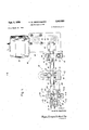
- Figure 1 is a front elevational view of the improved ink fountain mixer '01 agitator cf the present invention and shows the various elements that make up this improved mixer"'mounted on the elongated rack member;
- Figure 2 is a sectional view taken along line 2--2 of .
- Figure 1 showing the disposition cf the conicl mixer within the ink fountain and the manner in which the carriage of the mixer is mounted upon the elong'ated r-ack member;
- Figure 3 is a sectional view taken along line 33 of Figure 1 showing the detailed construction of the mounting for a cam member
- Figure 4 is a sectional view taken along line 44 of Figure 1 and shows the construction of the mounting brackets for the entire mixer organization
- Figure 5 is a sectional view taken along line 5 -5 of Figure 1 and shows in detail the construction cf the idler sprocket and its mounting upon the elongated rack member.
- ink fountain mixers of the type employing a conical shaped 01' frustum mixing member that is positioned in juxtaposition 110 the bed of the ink fountain and is simultaneously reciprocated through a given distance and rotated about its axis is generally superior to other types of known mixers with regard to maintaining the ink properly mixed and continuously und uniformly fed to the fountain ink rolls as well as acting as a mill to maintain the ink in a fine suspension.
- the present invention has for its object the provision of an improved ink fountai-n mixer of the type employing a conieal mixing member that is reciprocated through a given distance while being simultaneously rotated about its axis;
- Another object is t0 provide such an improved ink fountain mixer that is mounttad upon the printirig press solely by means of a pair cf spaced r'nounting brackets which are adapted to be secured to the frarne of the printing p1ess in an extremely simple and expeditious manner.
- a further object is to provide such an improVed inkffountain mixer that is readily adjustable for use with ditferent printing presses With the entire mechanisrn of the mixer being mounted upon an elongated rack member.which is supported solely by a pair of support brackets which are adjustable both longitudinally and rotatatively With respect t0 this rack.
- a still further object of the invention is to provide such an improved ink fountain mixer wherein the spaced brackets are provided With slots elongated in a direction laterally of the rack member so as to provide for limited adjustment of the ink fountain mixer in this lateral direction after the same is secured to the frame of the printing press.
- Another object of the invention is to provide such an improved ink fountain mixer which in addition to being simple to moufit upon the printing press and adjustable for use with difierent printing presses is extremely simple and economical in construction and yet highly reliable in its operation.
- the mixer of the present invention is of unitary construction in that all cf the elements are assembled into an operating unit with this unit then being secured to the printing press in its operative relation with the ink fountain of the press so that itis efl ⁇ ctive to maintain the ink therein properly mixed and in proper cbndition for fee-ding to the fountain ink roller, With this assembled unit being adjustable for use with diflerent types and sizes of printing press organizations.
- an elengated rack member which is of -geherally cylindrical configuration, although it is provided with a flattened surface throughout its length as well as being provided with gear teeth to form the rack of a rack and pinion drive.
- This elongated member is supported solely by a pair cf spaced brackets which are bored to receive this member and which extend laterally of the member.
- each of the brackets being made up of a pair cf members, one cf which is provided with an elongated slot through which a holt o1 capscrew is inserted for attachment to the other member with the slots permitting limited djustment in a direction laterally cf the elongated member.
- the connection between the brackets and the elongated member is such that the elongated member may be adjusted about its axis relative to the brackets and the brackets may be adjusted longitudinally of the rack member with means being provided to positively secure the brackets to the rack member in any desired adjusted position.
- Continuous reciprocatio'n of the mill assembly along the rack is provided by a motor driven drive mechanism which is mounted solely upon the elongated rack and includes an endless ehain positioned be-tween a pair of sprockets one of which is driven by an eleetric motor through a suitable speed reducer.
- Support for the rack 10 is derived solely through the brackets 16 which includes a mem-ber 17 Ih-at is provided with bore 18 within which the rack is received.
- the members 17 are slotted' at 28 to form in elfect a pair of' jaws between which the rack 10 may be firmly clamped, With cap screws 30 being efieotive to drawthe two sections or jaws of this me'mber of the bracket into clamping relation. Tlie construct'iori of member 17 is such that upon loosening eap screw 30 rack.
- bracket 10 may be r-otated within-bore 18 to any desired rotative position and the entire bracket may be adjustecl l'ongitudinallY of the raclewhile tightem'ng of this eap scr ew positively secures the bracket to the rack mernber.
- the ink within fou'ntain 32 is rnaintained properly mixed and in proper condition for feeding to the ink toller 34 by eonical mixer 36 which is.
- the lower portio'n of plate members44 isbentoutwardly torform support lip 46 for supporting ;andguidinga.portiomofthe chain drive mechanism described hereina.fter and by which the carriage is reciprocated along
- Coaxial with and extending f1'om corn'cal mill 36 is shaf-t 54 to which the mill is secured by set screw 56 With the outer end cf -this shaft being received in the spaced bearings 58 provided in frame 41.
- Rotation of the conical mill is produced in response to movement of carriage 40 along rack 10 -through the medium of a suita-bl-e gear train which includes idler pinion 60 mounted on shaft 62 which is seeured to carriage 40 and pinion 63 which is secured to shaft 58 and disposed intermediate the spaced bearings 58.
- the idler pinion is intermeshed With the teeth 14 of rack 10 and with pinion 63 so that a rack and pinion drive is established for rotating shaft 54 and accordingly mill 36.
- Bearing member 58 is fed over a threaded stud 58A which projects -fr0m carriage 40, and is secured thereto by the thurnb nut 58B so that by rern-oving the thumb nut 58B, the ink miXing Cone 36 and bearing aSsembly may be removed.
- Cont-inuous reciprocation of carriage 40 along rack 10 is provided through the motor driven endless chain 64 which is positioned between idler s-procket 66 and driv'ing sprocket 68 With the upper run of the chain -being received intermediate the g1iide members 48 and 50 of carriage 40 while the lower run pas'ses intermediate the guide membei 50 and support lip 46 of plate member 44.
- Idler sprocket 66 is supported from rack 10 -by means of support block 70 which is bored to reeeive the r-ack and is slotted at 72 so tl1at it may be firtnly elam'ped to the rack in any desired osition, with this being accornplished by means of the threaded shaft rnember 74 which islhreadedly received Within bore 76 provided in this' support block.
- s'haft mem-be'r 74 isbnlarged to provide a bearing' surface up'on which is reeeived sprocket 66
- the hexagonal head 78 of the shaft member With the hexagonal head 78 of the shaft member retaining the sprock'et' irip0siti0n and facilitziting adjustment of the shaft rnembe'r.
- Lubricat'i-on of the be'aring surface is provided through fit'ting 80 with the lubricant passing throug'l1 the channel 81 provided in the .shaft member and extending to the bea'1in'g surfaee.
- the drivefor chain 64 is provideid thr0ugh the motor assembly 82 which is supported solely by rack 10, being mounted on the end of the -raek through the mounting br'ackets 84, shown in dotted lines in Figure l.
- This motor asSembly includes an electric rhotor 86 mounted upon upstanding plate 88 and operative todrive sproeket 90 througli speed reducer 92.
- the driving sprocket 68 is driven ffom sprocket 90 through cha.in drive- 93 which is interposed betweeh sprocket' 90 and sprocket 94 with this lateral sprocket being mounten! upon the same shaft -as driving sprocket 68.
- carriage 40 Reciprocation of carriage 40 is accom plished by alternately interconnecting opposite runs of endless chain 64
- carriage 40 is provided with pawl meniber 96, shoWn in dotted lines in Figure 1, which is movable from a position where it engages the upper run of chain 64 and is free of the lower run to the position where it engag-es the lower runand is free of the upper run, with this pawl mernber being frictionally held in its desired position by any suitable meanssuch as a spring press detent, not sl1oWn.
- cam 98 which is supported from rack 10 by means of support block 100 adjustably secured to the rack by means ofcap screw l0l'while movement of pawl 96 from its lower toits upperoperative positon is provided by cam 102 which is likewise suppo-rted frorn rack 10 through a support bloek 104 adjustably received upon the rack and held in position by cap screw 106.
- Chain 64 is driven through motor assembly 82 in the direction indicated by arrow 108 so that when pawl 96 is in engage ment With the chain-carried lug 64' at the upper run of chain 64 carriage 40 is moved to the right as viewed in Figure l.
- pawl 96 is disengaged from the upper run of the chain and is engaged with the Ing 64 at the lower run of the chain so that carriage 40 is moved to the left until the pawl engages cam 102 which again moves it to its upper operating position disengaged from the lower run cf the chain and engaged With the upper run of the chain.
- carriage 40 is continuously reciprocated along rack through an amplitude Which is determined by the location of the cams 98 and 102 and cf course conical mill 36, which is carried by the carriage, is likewise continuously reciprocated as well as being rotated about its axis through the rack and pinion drive mechanism.
- a mixer for ink fountains the combination of an elongated mernber, said rnember being supported solely by a plurality of brackets connected to and extending laterally from said member and adapted to be attached to the side frames of the ink fountain of a printing press, a mill assembly mounted solely on said elongated member and including a carriage and a conical mill supported thereby, said mill assembly being movable along said elongated member and having means engageable with said mernber for rotating the conical mill in response to such movement, means by Which said conical mill may be adjusted relative to the brackets about an axis parallel With the direction of movement of the mill assembly along the elongated member, said last named means being operative to retain said conical mill and brackets in desired adjusted rotative positions, and motor means supported solely by said elongated means and constructed and arranged to continuously reciprocate said mill assembly along said member.
- each of the brackets is provided With means operative to provide for limited adjustrnent of the elongated mernber in a direction laterally thereof after the brackets are secured to a suitable frame member.
- the means operative to provide said limited adjustrnent includes a connection in the form of an elongated slot through which a holt means extends.
- said motor means includes a motor driven endless chain supported 011 a pair of spaced sprockets secured to the elongated member so that both runs of the chain pass in juxtaposition to said carriage, a movable driving member carried by said carriage and operative to alternately engage opposite runs of the chain so that said carriage rnoves with said runs, and cam means disposed at the extremities of reciprocation of the carriage and operative to carn the drive means from engagement With one run of the chain and into engagement With the other run.
- an ink fountain mixer of the type having a coulcal mill adapted to be continuously reciprocated within the ink fountain in juxtaposition to the bed thereof the conibinatiou of a rack, said rack being supported solely by a plurality of brackets extending laterally frorn said rack and adapted to support the Same from a suitable frame rnember, said brackets being connected to said rack in a manner which permits relative rotational and longitudinal adjustment of the brackets relative to said rack but provides for fixedly securing the brackets to the rack in desired adjusted positions, a mill assembly supported solely 011 said rack and including a carriage mounted on the rack in a manner providing for reciprocal movement therealong but preventing angular movement about the rack, a conical mill carried by said carriage and means for rotating the mill about its axis in response to reciprocation of the carriage along the rack including a pinion intermeshed With the rack, and motor means supported solely by said rack and constructed and arranged to.continuously reciprocate said mill assembly along said member.
Description
' H. w. GEGENHEIMER 2,849,952
Sept. 2, 195
Filed March l6 1956 INVENTOR.
Hao ld W. Gegenheimer TTORNEIS H. w. GEGENHEIMER ,849,952
Sept. 2, 1958 INK FOUNTAIN MIXER Filed March 16, 1 1956 1 2 Sheets-Shet 2 INVENTOR.
Harold W. Gegenheimer Fig. 5.
' TTORNEYS nited States Patent INK FOUNTAIN MIXER Harold W. Gegenheimer, Darien, Conn. I Application March 16, 1956, Serial N o. 572,076
8 Claims. (Cl. 101364) This invention relates to mixers for ink fountains and has particular relation to such mixers employed with printing presses to maintain the ink which is fed to the inking rolls in proper condition and insures uniform feeding.
Objects and advantages cf the invention will be Set forth in part hereinafter and in part Will be obvious herefrom, or may be learned by practice with the invenn'en, the same being realized and attained by means of the instwrnentalities and combinations pointed out in the appended claims.
The invention consists in the novel arts, constructions, arrangements, cornbinations and improvements herein shown and described.
The accompanying drawings, referred to herein and constituting a part hereof, illustrate one embodiment of the invention, and together With the description, serve to explain the principles of the invention.
In the drawings:
Figure 1 is a front elevational view of the improved ink fountain mixer '01 agitator cf the present invention and shows the various elements that make up this improved mixer"'mounted on the elongated rack member;
Figure 2 is a sectional view taken along line 2--2 of .Figure 1 showing the disposition cf the conicl mixer within the ink fountain and the manner in which the carriage of the mixer is mounted upon the elong'ated r-ack member;
Figure 3 is a sectional view taken along line 33 of Figure 1 showing the detailed construction of the mounting for a cam member;
Figure 4 is a sectional view taken along line 44 of Figure 1 and shows the construction of the mounting brackets for the entire mixer organization; and
Figure 5 is a sectional view taken along line 5 -5 of Figure 1 and shows in detail the construction cf the idler sprocket and its mounting upon the elongated rack member.
It is recognized that ink fountain mixers of the type employing a conical shaped 01' frustum mixing member that is positioned in juxtaposition 110 the bed of the ink fountain and is simultaneously reciprocated through a given distance and rotated about its axis is generally superior to other types of known mixers with regard to maintaining the ink properly mixed and continuously und uniformly fed to the fountain ink rolls as well as acting as a mill to maintain the ink in a fine suspension.
However, heretofore the fountain ink mixers of this type have been of such a construction or design that they r-equired what may be termed a tailor-made installation for each different printing press and even when pr0perly designed for the particular press installation of the mixer was still a rather substantial task necessitating the drilling ofmany holes and mounting of much equipment upon the frame of the printing press. In accordance with the novel organization of this invention this difliculty with regard to installation is completely 9Vercomc.
Patented Sept. 2, 1958 The present invention has for its object the provision of an improved ink fountai-n mixer of the type employing a conieal mixing member that is reciprocated through a given distance while being simultaneously rotated about its axis; Another object is t0 provide such an improved ink fountain mixer that is mounttad upon the printirig press solely by means of a pair cf spaced r'nounting brackets which are adapted to be secured to the frarne of the printing p1ess in an extremely simple and expeditious manner. A further object is to provide such an improVed inkffountain mixer that is readily adjustable for use with ditferent printing presses With the entire mechanisrn of the mixer being mounted upon an elongated rack member.which is supported solely by a pair of support brackets which are adjustable both longitudinally and rotatatively With respect t0 this rack. A still further object of the invention is to provide such an improved ink fountain mixer wherein the spaced brackets are provided With slots elongated in a direction laterally of the rack member so as to provide for limited adjustment of the ink fountain mixer in this lateral direction after the same is secured to the frame of the printing press. Another object of the invention is to provide such an improved ink fountain mixer which in addition to being simple to moufit upon the printing press and adjustable for use with difierent printing presses is extremely simple and economical in construction and yet highly reliable in its operation.
The mixer of the present invention is of unitary construction in that all cf the elements are assembled into an operating unit with this unit then being secured to the printing press in its operative relation with the ink fountain of the press so that itis efl\ctive to maintain the ink therein properly mixed and in proper cbndition for fee-ding to the fountain ink roller, With this assembled unit being adjustable for use with diflerent types and sizes of printing press organizations.
In accordance with the illustrative and preferred ernbodirnent of the invention there is providsd an elengated rack member which is of -geherally cylindrical configuration, although it is provided with a flattened surface throughout its length as well as being provided with gear teeth to form the rack of a rack and pinion drive. This elongated member is supported solely by a pair cf spaced brackets which are bored to receive this member and which extend laterally of the member. By means cf these brackets the entire mixer is m0u'nted upon the printing press with each of the brackets being made up of a pair cf members, one cf which is provided with an elongated slot through which a holt o1 capscrew is inserted for attachment to the other member with the slots permitting limited djustment in a direction laterally cf the elongated member. The connection between the brackets and the elongated member is such that the elongated member may be adjusted about its axis relative to the brackets and the brackets may be adjusted longitudinally of the rack member with means being provided to positively secure the brackets to the rack member in any desired adjusted position.
Mixing 0f the ink in the inkfount-ain is accom-ph'shed by a mill assembly which includes a conical mill rotatably carried -by a carriage which is mounted solely upon the elongated rack and in a manner which permits the assembly to move longitudinally along the rack but prevents it from moving 01' rotating =around the rack. The mill is rota-ted in response to movement of the assembly along the rack with =suitable gearing being provided for this purpose including a pinion in engagernent Wi-th the rack. Continuous reciprocatio'n of the mill assembly along the rack is provided by a motor driven drive mechanism which is mounted solely upon the elongated rack and includes an endless ehain positioned be-tween a pair of sprockets one of which is driven by an eleetric motor through a suitable speed reducer. This chain asses in close proxirnity to the c arriage of the mill assernbly which is provided Witl1 a cam actuated pawl member movable from a position Where it is engaged withone run of the =chain t a osition where it is engagecl With the other ru11 of the cl1ain to there-by drive the mill assembly first in one direction and then in the ozher direction along the elongated rack. Cam members are secu-red to the rack and1are efiective to cam this pawl member from one of its driving positions tothe other so tha=t a continuous recipro cation of the carriage is had w-ith the positioning of the cam mem-bers determining the =arnplitude of -this reeiprocat1on.
Thus all of the mechanism of rthe novel mixer of this invention is mounted upon the elongated rack mernber and in mounting the mixer upon the print-ing press it is merely necessary to secure the spaced brackets to the frame of the press in any desired manner, as by bolting Wi-th the adjustment alforded by the elongated slots in the brackets and the rotation of the rack member relative 'to the brache-ts being effective to properly position the mill Within the ink fountaih in a variety cf i'nstallations of diiferent designs.
II will be under-stood that the foregoing general descrip tion and the following detailecl d'escription as well are exernplary and explanatory cf the invention but are not restrictive thereof.
Referring now to the drawings, wherein like reference characters are used throughout to designate like ele;ments, the illustrative and preferred embodirnent =of the invention shown therein comprises the cylindrical rack having an outwardly* facing flattened surface 12 and a generally upwardly facing row of teeth 14 (Figures 2 and 4). Support for the rack 10 is derived solely through the brackets 16 which includes a mem-ber 17 Ih-at is provided with bore 18 within which the rack is received. These members 17 of the brackets 16 are provided With elongated slots 20 through which extencl :ap screws 22 by means of which these members are secured =to the L shaped arm 24 which forms a portiert of the bracket and which is adapted to be secured to the upper face 26 of frarne 27 of the printingpress in any suitable manner as by means of bolts 29or' the like. The members 17 are slotted' at 28 to form in elfect a pair of' jaws between which the rack 10 may be firmly clamped, With cap screws 30 being efieotive to drawthe two sections or jaws of this me'mber of the bracket into clamping relation. Tlie construct'iori of member 17 is such that upon loosening eap screw 30 rack. 10 may be r-otated within-bore 18 to any desired rotative position and the entire bracket may be adjustecl l'ongitudinallY of the raclewhile tightem'ng of this eap scr ew positively secures the bracket to the rack mernber. By means of the elongated slots 20 limited adjustment of. the rack relative to the frame of the printing press may be hadin =a direction Iater-ally of the axis of the rack o1 as viezwed in Figure 2 a vertical direction. The ink within fou'ntain 32 is rnaintained properly mixed and in proper condition for feeding to the ink toller 34 by eonical mixer 36 which is. positioned immediately above the -bed 38 of the fountain and is continuously reciprocated generally throughout-the lengtl1 of the fountain whileat the samel time-being rotated abo utu-its axi's. This' conical mixer 36 isrsupport'ed frorn rac'k 10 -through' the medium of carriage:40-whichis mounted=u;aonthe rack in a manner such that it may movewalong.the rack but is preventedfrom moving or rotating about the rack and includes frame 41- boredto receive raok 10; Secured 10 the r ear face offrarne=4iby capsorews 421isplate member 44' which has its inner surface in engagernent With the flatsurface 12 provided'onrack- 10 thereb'wpreventing rotation of frame 41 about the raek: The lower portio'n of plate members44 isbentoutwardly torform support lip 46 for supporting ;andguidinga.portiomofthe chain drive mechanism described hereina.fter and by which the carriage is reciprocated along rack- 10 with mernbers 48 and 50 spaced -outwardly from plate member 44 by spacers 52 and secured in place by cap screws 42 also being efleclive to guide this chain of the drive mechanisrn. Coaxial with and extending f1'om corn'cal mill 36 is shaf-t 54 to which the mill is secured by set screw 56 With the outer end cf -this shaft being received in the spaced bearings 58 provided in frame 41. Rotation of the conical mill is produced in response to movement of carriage 40 along rack 10 -through the medium of a suita-bl-e gear train which includes idler pinion 60 mounted on shaft 62 which is seeured to carriage 40 and pinion 63 which is secured to shaft 58 and disposed intermediate the spaced bearings 58. The idler pinion is intermeshed With the teeth 14 of rack 10 and with pinion 63 so that a rack and pinion drive is established for rotating shaft 54 and accordingly mill 36. Bearing member 58 is fed over a threaded stud 58A which projects -fr0m carriage 40, and is secured thereto by the thurnb nut 58B so that by rern-oving the thumb nut 58B, the ink miXing Cone 36 and bearing aSsembly may be removed.
Cont-inuous reciprocation of carriage 40 along rack 10 is provided through the motor driven endless chain 64 which is positioned between idler s-procket 66 and driv'ing sprocket 68 With the upper run of the chain -being received intermediate the g1iide members 48 and 50 of carriage 40 while the lower run pas'ses intermediate the guide membei 50 and support lip 46 of plate member 44. Idler sprocket 66 is supported from rack 10 -by means of support block 70 which is bored to reeeive the r-ack and is slotted at 72 so tl1at it may be firtnly elam'ped to the rack in any desired osition, with this being accornplished by means of the threaded shaft rnember 74 which islhreadedly received Within bore 76 provided in this' support block. By tightening down upon this shaft member block 70 is seeurely clamped torack 10 whil'e' wherx this shaft member is loosened the block rnziy move alng or about the rack. The outer end of s'haft mem-be'r 74 isbnlarged to provide a bearing' surface up'on which is reeeived sprocket 66 With the hexagonal head 78 of the shaft member retaining the sprock'et' irip0siti0n and facilitziting adjustment of the shaft rnembe'r. Lubricat'i-on of the be'aring surface is provided through fit'ting 80 with the lubricant passing throug'l1 the channel 81 provided in the .shaft member and extending to the bea'1in'g surfaee. The drivefor chain 64 is provideid thr0ugh the motor assembly 82 which is supported solely by rack 10, being mounted on the end of the -raek through the mounting br'ackets 84, shown in dotted lines in Figure l. This motor asSembly includes an electric rhotor 86 mounted upon upstanding plate 88 and operative todrive sproeket 90 througli speed reducer 92. The driving sprocket 68 is driven ffom sprocket 90 through cha.in drive- 93 which is interposed betweeh sprocket' 90 and sprocket 94 with this lateral sprocket being mounten! upon the same shaft -as driving sprocket 68.
Reciprocation of carriage 40 is accom plished by alternately interconnecting opposite runs of endless chain 64 With the carriage and for this purpose carriage 40 is provided with pawl meniber 96, shoWn in dotted lines in Figure 1, which is movable from a position where it engages the upper run of chain 64 and is free of the lower run to the position where it engag-es the lower runand is free of the upper run, with this pawl mernber being frictionally held in its desired position by any suitable meanssuch as a spring press detent, not sl1oWn. The pawl96-iscamn1ecl from its upper position in engagementwith the upper l'un of chain 64 to its lower position in engagement With the lower run of the chain by cam 98 which is supported from rack 10 by means of support block 100 adjustably secured to the rack by means ofcap screw l0l'while movement of pawl 96 from its lower toits upperoperative positon is provided by cam 102 which is likewise suppo-rted frorn rack 10 through a support bloek 104 adjustably received upon the rack and held in position by cap screw 106. Chain 64 is driven through motor assembly 82 in the direction indicated by arrow 108 so that when pawl 96 is in engage ment With the chain-carried lug 64' at the upper run of chain 64 carriage 40 is moved to the right as viewed in Figure l. Upon contacting cam 98 pawl 96 is disengaged from the upper run of the chain and is engaged with the Ing 64 at the lower run of the chain so that carriage 40 is moved to the left until the pawl engages cam 102 which again moves it to its upper operating position disengaged from the lower run cf the chain and engaged With the upper run of the chain. Thus carriage 40 is continuously reciprocated along rack through an amplitude Which is determined by the location of the cams 98 and 102 and cf course conical mill 36, which is carried by the carriage, is likewise continuously reciprocated as well as being rotated about its axis through the rack and pinion drive mechanism.
Since the entire mixer assembly of this inv6ntion is mounted upon rack membe'r 10 and since this rack member may be adjusted relative to support brackets 16 both in a direction longitudinally of the rack member and rotatively about the axis of the rack member and since slots 20 in the member 17 of the bracket provides limited lateral adjustment of the rack the mixer is readily adaptable to many different designs of printing presses With the mounting of the mixer upon the press being extremely simple requiring only the attachment cf arm 24 of the mounting brackets 16 to the press by means of cap screws 29 or in any other manner desired.
The invention in its broader aspects is not limited to I the specific mechanism shown and described but departures may be made therefrom, within the scope of the accompanying claims, without departing from the principles of the invention and without sacrificing its chief advantages.
What is claimed is:
l. In a mixer for ink fountains the combination of an elongated mernber, said rnember being supported solely by a plurality of brackets connected to and extending laterally from said member and adapted to be attached to the side frames of the ink fountain of a printing press, a mill assembly mounted solely on said elongated member and including a carriage and a conical mill supported thereby, said mill assembly being movable along said elongated member and having means engageable with said mernber for rotating the conical mill in response to such movement, means by Which said conical mill may be adjusted relative to the brackets about an axis parallel With the direction of movement of the mill assembly along the elongated member, said last named means being operative to retain said conical mill and brackets in desired adjusted rotative positions, and motor means supported solely by said elongated means and constructed and arranged to continuously reciprocate said mill assembly along said member.
2. The organization defined by claim 1 wherein the means by which said conical mill may be adjusted relative to the brackets is connected to the brackets.
3. The organization defined by' claim 2 wherein the elongated member is generally cylindrical and is received within a complementary bare provided in each of the brackets and wherein said means by which said conical mill may be adjusted relative to the bracket means is efrective in one position to positively secure said bracket means to said member and in another position is effective to allow said bracket means to move longitudinally of and about said member.
4. The organization defined by claim 1 wherein said elongated member is provided with a longitudinally extending flat surface and the carriage has a surface complementary to and in engagement with said flat surface and which is eflective to prevent rotation of the carriage about said mernber.
5. The organization of claim 1 wherein each of the brackets is provided With means operative to provide for limited adjustrnent of the elongated mernber in a direction laterally thereof after the brackets are secured to a suitable frame member.
61 The organization of claim 5 wherein the means operative to provide said limited adjustrnent includes a connection in the form of an elongated slot through which a holt means extends.
7. The organization of claim 1 wherein said motor means includes a motor driven endless chain supported 011 a pair of spaced sprockets secured to the elongated member so that both runs of the chain pass in juxtaposition to said carriage, a movable driving member carried by said carriage and operative to alternately engage opposite runs of the chain so that said carriage rnoves with said runs, and cam means disposed at the extremities of reciprocation of the carriage and operative to carn the drive means from engagement With one run of the chain and into engagement With the other run.
S. In an ink fountain mixer of the type having a coulcal mill adapted to be continuously reciprocated within the ink fountain in juxtaposition to the bed thereof the conibinatiou of a rack, said rack being supported solely by a plurality of brackets extending laterally frorn said rack and adapted to support the Same from a suitable frame rnember, said brackets being connected to said rack in a manner which permits relative rotational and longitudinal adjustment of the brackets relative to said rack but provides for fixedly securing the brackets to the rack in desired adjusted positions, a mill assembly supported solely 011 said rack and including a carriage mounted on the rack in a manner providing for reciprocal movement therealong but preventing angular movement about the rack, a conical mill carried by said carriage and means for rotating the mill about its axis in response to reciprocation of the carriage along the rack including a pinion intermeshed With the rack, and motor means supported solely by said rack and constructed and arranged to.continuously reciprocate said mill assembly along said member.
References Cited in the file of this patent UNITED STATES PATENTS 744,604 Pilkington Nov. 17, 1903 1,401218 Weldon Dec. 27, 1921 1,509888 Weldon Sept. 30, 1924 2103922 Van Guilder D60. 28, 1937 2234754 Gegenheimer Mar. 11, 1941
Priority Applications (1)
| Application Number | Priority Date | Filing Date | Title |
|---|---|---|---|
| US572076A US2849952A (en) | 1956-03-16 | 1956-03-16 | Ink fountain mixer |
Applications Claiming Priority (1)
| Application Number | Priority Date | Filing Date | Title |
|---|---|---|---|
| US572076A US2849952A (en) | 1956-03-16 | 1956-03-16 | Ink fountain mixer |
Publications (1)
| Publication Number | Publication Date |
|---|---|
| US2849952A true US2849952A (en) | 1958-09-02 |
Family
ID=24286244
Family Applications (1)
| Application Number | Title | Priority Date | Filing Date |
|---|---|---|---|
| US572076A Expired - Lifetime US2849952A (en) | 1956-03-16 | 1956-03-16 | Ink fountain mixer |
Country Status (1)
| Country | Link |
|---|---|
| US (1) | US2849952A (en) |
Cited By (5)
| Publication number | Priority date | Publication date | Assignee | Title |
|---|---|---|---|---|
| US3084625A (en) * | 1961-04-05 | 1963-04-09 | Baldwin Gegenheimer Corp | Ink agitator device |
| US3128699A (en) * | 1962-10-11 | 1964-04-14 | Baldwin Gegenheimer Corp | Vertical ink fountain agitator |
| DE1199285B (en) * | 1962-10-11 | 1965-08-26 | Baldwin Gegenheimer Corp | Agitator for the ink fountain of printing machines |
| US3710714A (en) * | 1970-11-09 | 1973-01-16 | Polygraph Leipzig | Stirring apparatus for circulating color or ink in the color chest of a printing machine |
| US4589337A (en) * | 1985-08-28 | 1986-05-20 | Hardin Philip J | Ink agitator for printing presses |
Citations (5)
| Publication number | Priority date | Publication date | Assignee | Title |
|---|---|---|---|---|
| US744604A (en) * | 1903-01-10 | 1903-11-17 | Herbert M Pilkington | Adjustable securing means. |
| US1401218A (en) * | 1921-05-26 | 1921-12-27 | Charles F Weldon | Mechanical inking apparatus |
| US1509888A (en) * | 1923-09-11 | 1924-09-30 | Charles F Weldon | Mechanical inking apparatus |
| US2103922A (en) * | 1935-09-19 | 1937-12-28 | Gen Electric | Mixing device |
| US2234754A (en) * | 1939-11-25 | 1941-03-11 | Gegenheimer William | Ink fountain mixer and agitator |
-
1956
- 1956-03-16 US US572076A patent/US2849952A/en not_active Expired - Lifetime
Patent Citations (5)
| Publication number | Priority date | Publication date | Assignee | Title |
|---|---|---|---|---|
| US744604A (en) * | 1903-01-10 | 1903-11-17 | Herbert M Pilkington | Adjustable securing means. |
| US1401218A (en) * | 1921-05-26 | 1921-12-27 | Charles F Weldon | Mechanical inking apparatus |
| US1509888A (en) * | 1923-09-11 | 1924-09-30 | Charles F Weldon | Mechanical inking apparatus |
| US2103922A (en) * | 1935-09-19 | 1937-12-28 | Gen Electric | Mixing device |
| US2234754A (en) * | 1939-11-25 | 1941-03-11 | Gegenheimer William | Ink fountain mixer and agitator |
Cited By (5)
| Publication number | Priority date | Publication date | Assignee | Title |
|---|---|---|---|---|
| US3084625A (en) * | 1961-04-05 | 1963-04-09 | Baldwin Gegenheimer Corp | Ink agitator device |
| US3128699A (en) * | 1962-10-11 | 1964-04-14 | Baldwin Gegenheimer Corp | Vertical ink fountain agitator |
| DE1199285B (en) * | 1962-10-11 | 1965-08-26 | Baldwin Gegenheimer Corp | Agitator for the ink fountain of printing machines |
| US3710714A (en) * | 1970-11-09 | 1973-01-16 | Polygraph Leipzig | Stirring apparatus for circulating color or ink in the color chest of a printing machine |
| US4589337A (en) * | 1985-08-28 | 1986-05-20 | Hardin Philip J | Ink agitator for printing presses |
Similar Documents
| Publication | Publication Date | Title |
|---|---|---|
| US4741266A (en) | Can decorating apparatus | |
| DE3116505C2 (en) | Rotary printing machine that can be used for various printing processes | |
| NO138749B (en) | STERILITY INDICATOR. | |
| US20070006757A1 (en) | Inking device of printing press | |
| US2849952A (en) | Ink fountain mixer | |
| DE2540794A1 (en) | DEVICE FOR PRINTING CANS | |
| US5272972A (en) | Arrangement for inking and doctoring in a pad printing machine | |
| DE2224210C2 (en) | Drive device for intermittently rotating feed cylinders in printing and punching machines | |
| CH616109A5 (en) | ||
| DE2808856C2 (en) | Inking unit drive | |
| DE2139830C3 (en) | Offset sheet-fed rotary printing press | |
| US3007403A (en) | Printing press attachment | |
| DE2725725A1 (en) | FLAT OFFSET PRESS | |
| EP0008924A1 (en) | Apparatus for providing ink feed to printing presses | |
| DE2606590A1 (en) | Vibrator damping and inking system - has device synchronising surface speed of vibrator roller with doctor roller | |
| US3710714A (en) | Stirring apparatus for circulating color or ink in the color chest of a printing machine | |
| US4848228A (en) | Damping device with biased transfer roller adjustment | |
| DE633956C (en) | Multicolor rotogravure printing machine with several single-color rotogravure printing units in a row | |
| CN216001862U (en) | Printing ink feeding device of plastic cup printing machine | |
| EP1447219A1 (en) | Rotary pad printing machine and method for printing objects with at least a printing module | |
| DE1140587B (en) | Stirring device for ink boxes of printing machines | |
| DE3039326A1 (en) | BLADE WITH A THIS FLOATING DRIVE | |
| DE1636321A1 (en) | Liquid supply device | |
| DE4340079C2 (en) | Offset printing machine with a numbering unit | |
| DE3811977C1 (en) |