US2838136A - Traffic adjusted standing time control - Google Patents
Traffic adjusted standing time control Download PDFInfo
- Publication number
- US2838136A US2838136A US602981A US60298156A US2838136A US 2838136 A US2838136 A US 2838136A US 602981 A US602981 A US 602981A US 60298156 A US60298156 A US 60298156A US 2838136 A US2838136 A US 2838136A
- Authority
- US
- United States
- Prior art keywords
- car
- relay
- contacts
- elevator
- doors
- Prior art date
- Legal status (The legal status is an assumption and is not a legal conclusion. Google has not performed a legal analysis and makes no representation as to the accuracy of the status listed.)
- Expired - Lifetime
Links
- 230000004044 response Effects 0.000 description 19
- 230000008859 change Effects 0.000 description 17
- 238000005303 weighing Methods 0.000 description 11
- 239000004020 conductor Substances 0.000 description 10
- 230000008093 supporting effect Effects 0.000 description 6
- 238000010586 diagram Methods 0.000 description 5
- 239000012530 fluid Substances 0.000 description 4
- 230000003068 static effect Effects 0.000 description 4
- 238000013459 approach Methods 0.000 description 3
- 230000003247 decreasing effect Effects 0.000 description 3
- 230000000994 depressogenic effect Effects 0.000 description 3
- 238000006243 chemical reaction Methods 0.000 description 2
- 230000008878 coupling Effects 0.000 description 2
- 238000010168 coupling process Methods 0.000 description 2
- 238000005859 coupling reaction Methods 0.000 description 2
- 239000013078 crystal Substances 0.000 description 2
- 230000007423 decrease Effects 0.000 description 2
- 239000012212 insulator Substances 0.000 description 2
- 230000007246 mechanism Effects 0.000 description 2
- 241000306729 Ligur Species 0.000 description 1
- 241000120020 Tela Species 0.000 description 1
- 230000009471 action Effects 0.000 description 1
- 230000008901 benefit Effects 0.000 description 1
- 229940000425 combination drug Drugs 0.000 description 1
- 230000003750 conditioning effect Effects 0.000 description 1
- 230000009699 differential effect Effects 0.000 description 1
- 230000000694 effects Effects 0.000 description 1
- 230000005686 electrostatic field Effects 0.000 description 1
- VKYKSIONXSXAKP-UHFFFAOYSA-N hexamethylenetetramine Chemical compound C1N(C2)CN3CN1CN2C3 VKYKSIONXSXAKP-UHFFFAOYSA-N 0.000 description 1
- 230000001976 improved effect Effects 0.000 description 1
- 230000001939 inductive effect Effects 0.000 description 1
- 230000000977 initiatory effect Effects 0.000 description 1
- 239000011810 insulating material Substances 0.000 description 1
- 230000004048 modification Effects 0.000 description 1
- 238000012986 modification Methods 0.000 description 1
- 238000005192 partition Methods 0.000 description 1
- 230000010363 phase shift Effects 0.000 description 1
- 238000000926 separation method Methods 0.000 description 1
- 230000001360 synchronised effect Effects 0.000 description 1
Images


Classifications
-
- B—PERFORMING OPERATIONS; TRANSPORTING
- B66—HOISTING; LIFTING; HAULING
- B66B—ELEVATORS; ESCALATORS OR MOVING WALKWAYS
- B66B1/00—Control systems of elevators in general
- B66B1/34—Details, e.g. call counting devices, data transmission from car to control system, devices giving information to the control system
- B66B1/3476—Load weighing or car passenger counting devices
- B66B1/3484—Load weighing or car passenger counting devices using load cells
-
- B—PERFORMING OPERATIONS; TRANSPORTING
- B66—HOISTING; LIFTING; HAULING
- B66B—ELEVATORS; ESCALATORS OR MOVING WALKWAYS
- B66B13/00—Doors, gates, or other apparatus controlling access to, or exit from, cages or lift well landings
- B66B13/02—Door or gate operation
- B66B13/14—Control systems or devices
- B66B13/143—Control systems or devices electrical
Definitions
- This invention relates to automatic elevators and in particular to improvements designed to reduce the standing time during which an elevator stands at a oor after a passenger has entered or left the car.
- the principal object of this invention is to provide means operating directly or indirectly through the floor or threshold of the car for sensing the exit or entrance of a passenger from or into the car together with means for cutting short the waiting or standing time that the elevator waits at a floor before proceeding to the next door.
- Another object of the invention is to provide weight sensitive means in the ioor of the carin order to sense the exit or entrance of a passenger from or into the car.
- Another object of the invention is to provide means acting directly or indirectly through the floor or threshold of the car for detecting and distinguishing between passengers entering the car and those leaving the car for controlling the waiting time intervals accordingly.
- the entrance or exit of a passenger into or from the elevator car is detected by the pressure or presence of a passengers foot on the threshold of the car or the oor of the elevator car or the apparent change in weight of the car.
- the detecting means may take the form of transitory load weighing devices, i. e. load weighing devices responsive to a change in load rather than the total load, or to electrostatic devices located in the threshold of the car and actuated by the presence of or passage of an object close to the surface of the threshold.
- the pressure responsive devices may take the form of weighing devices that carry the entire weight of the car and load, weighing devices in which the iioor of the car is the platform of the Weighing device, treadles adjacent the door of the car, or thresholds supported by weighing devices.
- the detecting means may also take the form of inertia operated devices which respond to the movement of the car as permitted by the elasticity of the supporting cables as a person enters or leaves the car. Regardless of which type of sensing device is employed the device responds momentarily to an addition or subtraction of load or to the presence of a person on or moving across the threshold of the car and responds by interrupting the operationl of one of the timing relays used to determine the standing time that a car waits at the floor.
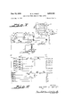
- Figure I is a simplied schematic illustration of an operating system for a single elevator car.
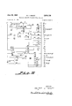
- Figure Il is a schematic diagram illustrating suitable stopping circuits for stopping the car at various oors in response to landing calls registered at such floors.
- Figure Ill is a simplified schematic diagram of a portion of the elevator control including the means for registering and responding to car calls and for operating the door mechanism of the car.
- Figure lV is a simplified schematic diagram of an elevator car and sling illustrating the location of a switch for sensing changes in the load in the car.
- Figure V is a similar arrangement of an elevator car with a load weighing mechanism that occupies only a portion of the oor of the car.
- Figure VI is a greatly enlarged diagrammatic view of a transitory switch suitable for use according to the in* vention.
- Figure VH is a schematic illustration of another form of switch suitable for use according to the invention.
- Figure VIH is a simpliiied schematic diagram of an inertia operated device suitable for detecting changes in load in the elevator car.
- Figure IX is a simplified schematic View of an elevator car showing the location of an electrostatic threshold used for detecting the entrance or exit of passengers.
- Figure X is a simplified schematic wiring diagram of electrical circuit suitable for use with the electrostatic threshold.
- an elevator car 1 is suspended by cables 2 that are trained over a drive sheave 3 and connected to counterweights 4.
- the car is driven up and down by means of elevator drive motor 5 having an armature shaft 6 on which the drive sheave 3 is mounted.
- a brake 7 is arranged to operate on a brake drum 8 mounted on the armature shaft 6 to hold the elevator stationary as long as the motor 5 is deenergized.
- variable voltage direct current for the elevator drive motor 5 such current being supplied from a generator 9 having armature 10 connected to the elevator drive motor 5.
- the drive motor S has a shunt field 11 that is continuously energized from direct current power lines L1 and L2 by way ot leads 12 and lead 13.
- the variable voltage generator 9 has a shunt field 1f; that is connected to the lines L1 and L2 by way of reversing contacts UF and DF, a rheostat 15 and a lead 16 connecting the reversing contacts to the rheostat 15.
- the rheostat 1S is arranged to increase the current flow through the shunt iield 14 as its slider 17 is moved either way from a center position.
- the position of the slider 17 on the rheostat 1S and thus the speed of the elevator is controlled by a diiierential gear 18 operating between the elevator drive motor shaft 6 and a shaft 19 driven by a constant speed advance motor 20.
- the advance motor 20 also drives a door selector machine 21 which serves to switch the various circuits required for car position signals and for the control of the elevator car as it travels up and down the elevator shaft.
- the seiector machine 21 includes a brush carriage 22 that is carried on chains 23 up and down over the face of a contact board or contact strips 24 substantially in synchronism with the movement of the car in the shaft.
- the floor selector machine 21 is driven 3 directly by the motor and the car controls cause the car to follow with a positional lag depending upon the speed.
- the sequence of events as the car moves from one floor and travels to another begins with the advance motor starting first to drive the brush carriage 22 toward the contacts on the board 24 representing the destination floor.
- the advance motor drivesl the floor selector machine it also drives the differential 1S and thus moves the slider 17 in a direction tending to energize the eld 14 of the generator 9 and thus provide voltage to drive the elevator motor such that the motor 5 moves the car from the previous door toward the selected floor.
- the slider 17 moves fairly rapidly away from the central position on the rheostat.
- the elevator motor 5 starts and acceleratesrthe shaft 6 drives the Y Vdifferential 18 in a direction tending to cancel the drive from the advance motor shaft 19 thus slowing up the movement of the slider 17 until ,it finally stops when the speeds of the elevator motor 5 and the advanced motor 20 correspond.
- the slider 17 is displaced substantially its maximum amount from the central position thus corresponding to full speed movement of the car and because of the differential action the position of the selector machine brush bar 22 actually leads the equivalent position. of the elevator car 1 bysuch a distance as may be required for a slow down for the next stop.
- the advance motor is preferably a synchronous single phase alternating current motor, preferably of the inductor type, so as to ensure rapid starts and stops as well as constant speed while in operation.
- the diiferential is arranged so that the position of the brush bar 22 leads the equivalent position of the elevator car 1 by as much as one and onehalf or two floors of the building. This is the distance required to stop without causing the passengers objection- Y
- the switch 29 is Yof a transitory nature having means so that it operates in response to a change in load rather than in a continued steady load and is arranged to vary the standing time at a floor in response to passenger movements.
- Figures II and III illustrate circuits for registering landing calls and causing the elevator to respond thereto and for registering car calls and causing the elevator to respond'to such calls as well as portions of the circuit for operating the doors and determining the time interval during which the doors shall remain open. While only a few of the relays are shown in Figures Il and III it is to be understood that an ordinary elevator system contains many more relays used to secure the various operations required in normal service.
- the relays whose coils are Vshown in the figures include:
- landing calls are registered on the SU and SD series of relays which preferably are latch type relays that are tripped, to register a call, by operation of push buttons 31 and which are restored to non-registering position, as the call is answered, by alcircuit that is completed, at line 12, from lead L3 through the restoring coil of the relay, a selector machine brush 31, up or down directional relays UF or DF, and the stopping relay contact S.
- relays which preferably are latch type relays that are tripped, to register a call, by operation of push buttons 31 and which are restored to non-registering position, as the call is answered, by alcircuit that is completed, at line 12, from lead L3 through the restoring coil of the relay, a selector machine brush 31, up or down directional relays UF or DF, and the stopping relay contact S.
- the stopping relay S in line 18 responds to registered landing calls as brushes 32 and 33 connected through contacts DF or UF in lines l or 2'3 touch energized contacts corresponding to registering landing calls.
- This circuit, in line 1S includes contacts of the by-pass relay BP and brake relay BK so that the stopping relay S cannot be energized if the car is loaded and is byassing si nals or when it is sto ned inductor motor having the two elds 34 and 35, the
- the car button-circuit for registering destination calls is'shown in Figure HI, lines 35 to 41, wherein the push buttons shown at the right in lines 35 to 4b are car buttons installed in the car for registering calls for the particular doors.
- the car buttons for the terminal doors may be omitted and the leads continued direct from the lead L4 to the car call contacts of the selector machine represented by the small circles 38 cooperating with a selector machine brush 39.
- the selector machine-brush 39 When the car is running and the selector machine-brush 39 reaches an energized contact 38 it completes a circuit from the lead L3 to the lead L4 through the car call stopping relay SC.
- No latch relays are employed in connection with the car button relays but rather holding coils are arranged directly behind each of the buttons in the assembly in the car to magnetically hold the buttons in depressed condition once they are depressed. These coils are not strong enough to draw the buttons to depressed positions and thus the buttons remain open or circuits deenergized until the calls are actually registered.
- the circuit to the holdin g coils not shown in the drawings, is arranged to be momentarily broken each time the car is reversed. Thus all the car calls are canceled at that time.
- the car call relay SC or the landing call stopping relay S When either the car call relay SC or the landing call stopping relay S is energized in response to the answering of a call, it closes its contacts SC or S in lines 33 or 32 so as to energize a series of selector machine stopping contacts 4G, there being one such contact for each door and these being connected in parallel. These now energized contacts 4d through brushes 41 or 42, depending upon the direction of travel, energize the stopping relay V in line 36. The contacts RHZ also shown in this line are closed as long as the elevator is in motion. As soon as the relay V is energized it opens its contacts in lines 31 and 33 to deenergize the advance motor 20 and the advance motor relay AM.
- This relay immediately drops out and, to accurately position the brush bar 22 of the oor selector machine, closes its contacts AM in the vertical leads at the level of line 35 so as to connect the advance motor 2t? through these now closed AM contacts to the brushes 4i and Assuming that the car had been traveling down such that the brush 42 was on an energized contact current is maintained to the advance motor until the brush 42 leaves the contact 40. Should the advance motor overrun, the following brush 41 reaches the energized contact and energizes the advance motor for reverse rotation. Until the elevator stops after the advance motor stopped the elevator motor drives the differential in a direction to drive the rheostat back to center and the reaction torque from the differential is applied to the advance motor.
- this reaction torque is suilicient to drive the advance motor and selector machine away from the proper position if it were not for the current supplied through the brushes 41 or 42 to the advance motor as soon as it departs from its selected position with the energized contact between but not in contact with either the brushes 41 or 42.
- the se* lector machine brush carriage and advance motor are electrically held in theircorrect position while the elevator is coming to a stop at the selected floor.
- the leveling relay contact LU in line 46 closes so as to complete a circuit to a door opening relay OP which controls the door motor to effect opening the doors.
- the relay Oi When the relay Oi) is energized it closes its contacts in lines 42 and 44 so as to connect the door motor, shown in line 44, to the leads L3, L4, and L5. lesistances 43 and 44 are included in the leads from the supply leads L4 and L5 in order to reduce the starting torque and permit the motor to stall if the door sticks.
- the door reaches its fully open position it opens a limit contact 45 shown in line 46 so as to break the circuit to the door opening relay OP.
- Door opening relay OP in addition to operating the door motor, controls contacts shown in lines 48 and 54.
- the contacts in line 4S in series with brake contacts BK operate the auxiliary timing relay TRLA which establishes or determines time interval that the car will wait for a passenger before initiating a door closing operation sequence.
- Relay TRLA seals itself in through a circuit shown in line 49 which comprises a pair of normally open TRLA contacts, a pair of normally closed TRL relay contacts, and a pair of normally open WT contacts which are part of the passenger sensing equipment.
- the WT contacts are closed in normal operation and opened momentarily as a passenger enters or leaves the car.
- the auxiliary timin. relay TRLA also closes its contacts TRL/ft.
- the door closing and car starting sequence of operation is controlled or initiated by a second timing relay TR shown in line 52 of Figure lll.
- This relay of the luX decay timing variety, is energized through a rectifier 45 from the lead L3 and through parallelly connected contacts of the emergency relay EM in line Si, advance motor relays AM in line S2, timing relay TRLA in line 53, and door opening OP in line 54.
- the timing relay TR is energized as long as the emergency relay EM is deenergized so as to close its contact in line 51, cr the advance motor is operating, or the TRLA timing relay energized, or the door opening relay is energized during the door opening operation.
- the timing relay TR times a short interval following the simultaneous opening of afl of these contacts and at the end of such short time interval closes its contacts in line 47 so as to complete a circuit to the car starting relay CS shown in line 47. lf the doors are not opening so as to open the contacts OP in line 47 relay CS is energized and immediately begins a :car starting sequence which begins by operating a door closing relay which in turn closes its contacts CL in lines 43 and 45'to operate the door motor in a direction to close the door. As soon as the door is completely closed the gate relay Clo-ses contacts G in line 31 to start the advance motor and the elevator motor.
- the timing relays TRL and TR constitute sequentially operating timers the first of which times a maximum waiting time interval measured from the start of the open- Search 7 ing of the doors as the car stops at a floor. This is effected by the closing of the OP contacts in line 48.
- the second timing relay TR constitutes a second timing means for measuring a second time interval which is measured from the completion or interruption of the operation from the first timing relay as evidenced by the opening of the TRLA contacts in line 53 or the opening of the OP contacts should the doors have started to close and been reopened by the entrance of a passenger during the closing time.
- the presence of the other contacts in lines 51 to 54 cause the second timing relay TR to time its interval from the instant that the car starting sequence may be safely initiated. This time interval ordinarily is in the order of a second or slightly less since that is the average or safe time that may be employed to allow a passenger to safely clear the door before the door starts to close.
- the timing interval established or measured by the irst timing relay TRL may be cut short by the entrance or exit of a passenger which causes momentary separation of WT contacts in line 49.
- These contacts are preferably constructed as part of a transitory switch operated in conjunction with load weighing equipment or as part of a sensitive treadle sensitive either to the weight of a person stepping on it at the threshold of the car or by change of an electrostatic field resulting from a passengers foot on the threshold or passing close above the threshold.
- the timing of the maximum time interval as measured by the iirst timing relay TRL is cut short or interrupted as soon as a passenger enters or leaves the car.
- Figures IV and V illustrate two of several locations that may be selected for the transitory load weighing switch.
- Figure IV shows an elevator car or elevator cab 51 supported on a sling 52 that comprises a bottom beam 53, side rails 54 and a cross head 55 to which a hoisting cable or cables 56 is attached.
- the sling 52 is guided by rollers 57 that engage vertical rails 58 in the hatchway.
- the transitory switch 59 is mounted on a secondary cross head 60 in position to measure the deflection of the cross head 55 as the load in the car changes.
- the transitory switch 59 has contacts WT shown in line 49 of Figure III and arranged when separated or open to interrupt the operation of the irst timer relay TR1.
- the transitory switch 59 may have contacts arranged to operate whenever a passenger' enters or leaves the car.
- a passenger enters the weight in the car 51 is increased so as to increase the dellection of the cross head 55 to which the hoisting cable 56 is attached.
- This additional deflection results in a decrease in distance between the cross heads S and 60 at the switch location and a consequent operation of the switch.
- the deflection of the cross head 55 is decreased and the spacing between the cross heads 55 and 60 is increased which again may be sensed by the switch 59.
- this position for the transitory switch is selected it is essential that the car be guided by rollers rather than friction guide shoes running on the vertical rails 58.
- the passenger responsive means may also take the form Vot treadle 61, Figure V, located adjacent the door of of the car 62.V Again it is necessary that the switch re-v entering or leaving a car and in this case. as in that shown in Figure IV, a transitory switch is employed, i. e., one that is arranged vto open or close its contacts momentarily as a load is applied and maintained.
- Figure V shows the treadle as a small platform supported on a linkage
- the ordinary form of electric mat is also suitable for this purpose, such a mat usually being constructed of rubber with electrical conductors embedded in the mat and arranged to be closed or form a closed circuit when pressure is applied to the mat.
- VThe transitory nature of such a Vmat may be achieved by connecting the leads through a timing relay that will hold a contact-closed momentarily for each energization and locating the mat close to the door so that persons would not ordinarily remain standing on it.
- load sensitive electrical controls such as piezo-electric crystals or strain gauges
- a simple dashpot form of transitory switch is preferred.
- FIGS VI and VII Two examples of such transitory switches are illustrated in Figures VI and VII.
- an electrical switch having an operating plunger 71 is mounted from an upper cross head member 72, corresponding to the auxiliary cross head 60, by means of a stiff spring 73.
- a stud 74 depending from the cross head 72 cooperates with the operating plunger 71 to operate the switchv whenever the spring '73 is compressed.
- the switch 70 is also connected to the lower cross head 75 by means of a mounting plate 76 and a hydraulic bellows 77.
- the mounting plate 76 is also connected to the upper cross head 72 by a second bellows 7S large enough in diameter to completely enclose the rst.
- the mounting plate 76 is spaced from the cross head 75 by a shallow cup shaped member 79 so as to form a hydraulic chamber beneath the mpunting plate 76.
- Oriices and 81 connect the interiors of the bellows 78 and 77 respectively to the chamber formed within the cup-shaped member 79 so as to provide for the tlow of uid from one bellows into the other.
- the system is usually tilled with fluid at least to the level of the switch 70 with the inner bellows 77 completely lled with fluid and an air space left above the fluid in the outer bellows 77
- This assembly is used as the transitory switches 59 in Figure IV or 65 of Figure V and arranged so that the cross head members 72 and 75 or linkage assembly with the system as used in Figure V approach each other or deflected toward each other with an increase in load.
- the switch is operated momentarily in this arrangement when the load is applied so as to force the cross head members 72 and 75 toward each other because the hydraulic duid trapped within the bellows 77 provides a momentary firm resistance to any relative'movement between the switch 7h and the lower cross head 75 so that the spring 73 is deflected or compressed enough to allow the stud 74 to operate the plunger l 1l of the switch 70.
- the spring extends so as to release the force between the plunger 71 and stud 74 thus opening the switch. Should the load be increased a second time the same action occurs again and so on for subsequent operations as additional passengers enter the car.
- the tlexibility of the bellows 77 is much greater than the spring 73 so that over the normal operating range the static position of the switch 7l) isV fixed relative to the upper cross members V72 and is deflected only momentarily as hydraulic iluid is forced from the bellows 77.
- the switch illustrated in Figure VII works on the same principle in that it is operated by relative motion or deflection between an upj'er member 85 and a lower member 86' which may be portions of the cross heads of the car or of the linkage supporting the sensitive treadle.
- a lever 87 fulcrumed from the upper member 85 has its end 88 embraced between leaf contacts 89 and 90 which are spaced by an insulator 91 so that each of the contact leaves 89 and 9i) contact the lever 88 but such that contact with one or the other is broken by a relatively small movement of the lever in either direction.
- the insulator 91 is also attached to the upper member 85 so as to move with that member.
- the lever 87 is also connected to the lower member 86 through a dash pot 92 which is adjusted to be rather stiff in its response or resistance to relative movement between the lower member 86 and the lever 87 but which has very little static friction so that the leaf contacts 89 and 90 may overcome the residual or static friction of the dash pot 92 so as to hold both contacts closed in the normal static condition.
- the switch operates to break the connection between the common lead 93 and a lead 94 connected to the upper leaf spring contact 90 whenever the load increases and to break the contact between the common lead 93 and a lead 95 connected to the lower leaf spring contact 89 whenever the load in the car decreases.
- the switch 7) or the circuit taken through the leads 93, 94 or 93, 95 correspond to the WT contacts appearing in line 49 in Figure 1li' so as to break the circuit to the maximum standing time interval timer TRLA as soon as a change in load in the car occurs.
- the leads 94 and 95 are connected to the WT contacts so that opening of either set of contacts breaks the circuit.
- the cir cuit is connected between the common lead 93 and the lead 94 which circuit is broken when a person enters a car but is not broken by the exit of a passenger.
- This circuit is thus responsive to the direction of travel of the passenger as to whether he is entering or leaving and affects the circuit accordingly.
- switches shown in Figures Vl and VII are merely representative of structure that may be used to produce the desired results of momentary circuit interruption as the load in the car is changed.
- Other types of equipment may serve the same purpose, for example many of the electrical load weighing devices using strain gauges, piezoelectric crystals, inductive devices, etc. can be arranged to respond to changes in load as well as to the total load.
- the sensitive door or threshold of the car may also, as suggested earlier, be of an electrostatic nature such that changes in the electrostatic capacity of a sensing lead to ground varies according to the presence of an object on or immediately above the threshold.
- Figures IX and X illustrate structure employed for this type of operation.
- an elevator car is shown positioned adjacent a landing 106 and is equipped with an electrostatic threshold 107 arranged in the path of a passenger entering or leaving the car.
- the threshold is sensitive to the passage of objects either in contact with it or closely adjacent to it. Circuits used in conjunction with the threshold are illustrated in Figure X.
- the threshold 107 comprises a U-shaped channel 108 of an electrically conductive material divided into two troughs by a center partition 109. Each section is filled with insulating material and near the surface is provided with a conductor 110 extending lengthwise of the threshold and arranged to be energized by a high frequency alternating current.
- the high frequency current for energizing the conductors 11@ is obtained from a capacitive bridge circuit 111, one for each conductor ⁇ 110.
- Each bridge circuit is fed by an oscillator 112 which may be of any conventional type.
- a cathode or electron coupled type is illustrated.
- a tank circuit comprising condenser 113 and an inductance 114 is connected between a grid 115 of the oscillator 112 and ground.
- a cathode 116 of the oscillator is connected to a tap on the inductance 114.
- a plate 117 of the oscillator is connected to a B+ lead 118 through a primary 119 of a coupling transformer 120.
- the transformer has a secondary 121 that feeds the bridge circuit 111.
- the vbridge circuit 111 comprises two condensers 122, 123 serving as ratio arms, a variable condenser 124 serving as a tuning adjustment and the fourth arm of the bridge is made up of the capacitance of the connected conductor 110 to ground.
- the equivalent capacitance of the conductor 110 to ground is indicated by the dotted condenser symbol included in the layout of the bridge 111.
- the output voltage or the capacitive bridge 111 is taken through a lead 125 to a grid 126 of a detector tube 127 that is operated as a cathode loaded electronic voltmeter to develop a direct current voltage on its cathode lead 12S corresponding to the voltage developed in the bridge circuit.
- the cathode lead 128 is connected to ground through a parallel combination of a resistor 129 and condenser 130 having a time constant long in comparison with the time of one cycle of the oscillator 112.
- the voltage developed at the cathode 128 which varies according to the capacitance to ground of the conductor 113 which in turn varies according to the presence or absence of objects immediately above the conductor, is coupled through a coupling condenser 131 to a grid 132 of a relay control tube 133.
- the grid 132 is also grounded through a resistor 134 which in combination with the condenser 131 provides a time constant in order of one quarter to one half second.
- the value of a cathode or a fixed bias preferably is selected so that a relay 136 in the plate crcuit is in its non-operating condition when there is no change in the voltage at the detector cathode 128.
- unbalanced condition of the bridge circuit 111 produces a signal that drives the grid positive to increase the i'iow of current through the tube and thus operate the relay.
- the relay Because of the capacitive connection from the detector to the relay tube 133 the relay responds only to changes in capacity and not to a steady unbalance.
- the relay includes normally closed contacts 140 corresponding to the WT contacts that are included inthe first timer circuit to interrupt the operation of that timer when a person crosses the' threshold.
- a similar circuit including oscillator, bridge and detec tor is used in conjunction with the second sensing conductor 10 of the sensitive threshold and its output relay tube 141 is connected to operate a second relay 142.
- the relay is normally deenergized to open its contacts 143 as long as there is no change in signal voltage from the sensitive threshold. However, when there is a change in voltage resulting from a change in capacitance Y 1 1 at the threshold the relay is momentarily energized so as to close its contacts 143.
- the circuit including the relay 136 with its contact 140 is all that is required. However, if it is desired to sense the direction of movement of the passenger across the threshold as Well as the fact that a passenger has crossed the second relay 142 and its control circuit must also be used.
- the second relay 142 alone is energized a circuit is completed from a grounded lead 144 through contacts 143 of the second relay 142, contacts 14S of the first relay 136 to the grid 132 of the first relay tube 133. This circuit prevents a first relay tube 133 from operating in response to change capacitance in its bridge circuit.
- the second relay 142 always responds but the rst relay responds only if the second has not.
- the threshold is mounted so that the left hand conductor 110 of Figure X is adjacent the landing so that a person entering the car will cause the relay 136 to operate in advance of the relay 142 and thus interrupt the timing.
- the operation of the relay 136 by opening its contact 145 removes the grounding circuit from the grid 132 of the relay tube 133 and permits it to operate in response to its change of capacitance of signal.
- the circuit responds to a person entering a car.
- the circuits are arranged so that the first timer relays TRL and TRLA operate only if the car stops in response to a landing call or combination of landing and car calls.
- the preference is required when the car stops for a landing call and a passenger leaves the car. If the departing passenger interrupted the timing it is doubtful if the prospective passenger could reach the doors before they started to close.
- the directional responsive system provides the required time for the entering passenger under any circumstance.
- an elevator control system in combination, means for stopping a car at a fioor for which a call is registered, means for opening the doors of the car as it stops at a floor, means for reclosing the doors and starting the car for travel to the next stop, first timing means arranged to delay the reclosing of the doors for artime interval measured from the opening of the doors as a stop is made, second timing means for delaying the reclosing of the doors for a minimum time interval measured from the end of the first time interval, and transitory Weight sensing means arranged to detect changes in load in the car, said weight sensing means being connected to the first timing means to terminate the operation of the first timing means upon the occurrence of a change in load in the elevator car.
- an automatic elevator control system in combination, means for opening the doors of an elevator car as the car stops at a door, means for reclosing Vthe doors, a first timer arranged to delay the reclosing of the doors for a time interval measured from the opening of the doors as a stop is made, a second timing means for delaying the reclosing of the doors for a minimum time interval measured from the end of the first time interval, transitory weight sensitive means supporting at least a portion of the door of the elevator car, and means connected to the transitory Weight sensitive means and the ray first timer for terminating the operation of the irst timer immediately upon a change in load in the car.
- an automatic elevator control system in com bination, means for opening the doors of an elevatol car as the car stops at a floor, means for reclosing the doors, a first timer arranged to delay the reclosing of the doors for a time interval measured from the opening of the doors as the car stops, a second timer for delaying the reclosing of the doors for a minimum time interval after termination of the first time interval, transitory weight sensing means for supporting the elevator car, and means connected to the Weight sensing means and responsive to a change in weight for terminating operation of the first timer.
- an elevator .car arranged to serve a pluralityrof floors of a building, hall call means for registering calls for service from the various oors, car call means for registering destination calls, means for opening the doors as the car stops at a floor, means for reclosing the doors, a first timer arranged to delay the reclosing of the doors for a Vtime interval measured from the opening of the doors when a stop is made in response to said hall call means, a second timer for delaying the reclosing of the doors for a minimum time interval measured from the opening Vof the doors, when a stop is made in response to the car call means or the expiration of the first timer interval whichever is later, transitory Weight sensing means responsive to the load in theV elevator car, and means connected to the weight sensing means and the first timer adapted to interrupt the operation of the first timer immediately upon an increase in load in the car.
- an elevator car arranged to serve a plurality of oors, hall call and car call means for registering calls for service, means for stopping the car ata oor in response to a call, means for opening the doors as the car stops at a floor, means for reclosing the doors, a first 'timer arranged to delay reclosing of the doors for a first time interval measured from the opening of the doors when the car stops in response to a hall call, transitory load Weighing means responsive to changes in load in the elevator car, .said load responsive means being arranged to interrupt operation of said first timing means, and second timing means for delaying reclosing of the doors for a minimum time interval after interruption or expiration of the first time interval or openingV of the doors in response to a car call.
- a control system in which the weight sensitive means includes a resiliently supported mass and means for detecting movements of the car With respect to said mass.
- an elevator car arranged to serve a plurality of oors, means for opening the car doors when the car stops at a oor, means for reclosing the doors, a first timer arranged to delay reclosing of the doors for a first time interval measured from the opening of the doors, a pressure sensitive tread extending across the path -of a person passing through the door way of the car, said sensitive tread being connected to the first timer and arranged to terminate the irst time interval, and a second timer arranged to delay reclosing of the doors for a minimum time after opening of the doors or termination of the first time interval whereby the doors are held open to await the entrance or exit of a passenger ⁇ and promptly closed after the entrance or exit of the passenger.
- an elevator car arranged to serve a plurality of floors, hall call means and car call means for registering calls for service, means for opening the doors as the car stops for a floor, means for reclosing the doors, a rst timer arranged to delay reclosing of the doors for a rst time interval measured from the opening of the 13 doors in response to a hall call, a sensitive tread arranged in the elevator car, said tread being divided to be directionally sensitive and connected to the first timer to terminate the rst time interval when the tread responds to a passenger entering the ear, and a second timer adapted to delay reclosing of the doors for a minimum time interval following opening of the doors in re- References Cited in the tile of this patent UNITED STATES PATENTS Suozzo Apr. l4, 1953 Nikazy Aug. 14, 1956
Landscapes
- Engineering & Computer Science (AREA)
- Automation & Control Theory (AREA)
- Mechanical Engineering (AREA)
- Computer Networks & Wireless Communication (AREA)
- Elevator Control (AREA)
Description
June 10, 1958 w. A. NlKAzY 2,838,136
TRAFFIC ADJUSTED STANDING MME CONTROL Filed Aug. 9, 195e 5 sheets-sheet 1 23 ooooo 22\\ ooooo 0 INVENTOR. Eig- ZZ- WALYTER A. /VKAZY M2wf June 10, 1958 `w. A. NIKAzY 2,838,135
TRAFFIC ADJUSTED STANDING TINII` CONTROL Filed Aug. 9, 1956 5 Sheets-Sheet 2 @M4/MS June 10, 1958 w. A. NlKAzY 2,838,136
TRAFFIC ADJUSTED STANDING TIME CONTROL Filed Aug. 9, 1956 5 Sheets-Sheet 3 a f56 (59 J f6@ f "r` l "57 57 r -Hl Fi g- 1Z- INVENTOR.
WALTER A. /V/KZY June 10, 1958 w. A. NlKAzY 2,838,136
TRAFFIC ADJUSTED STANDING TIME CONTROL Filed Aug. 9, 1956 5 Sheets-Sheet 4 WL 7%?? A /V/KZY June 10, 1958 w. A. NlKAzY 2,833,136
TRAFFIC ADJUSTED STANDING TIME CONTROL Filed Aug. 9, 1956 5 Sheets-Sheet i rm-w f/OS fgm Jig. n.7
IN V EN TOR.
WAL 155/? A. /v//mzy @MQ/M United States Patent() TRAFFEC ADJUSTED STANDING TllVIE CGNTROL Walter A. Niirazy, Toedo, Ohio, assigner to Toledo Scale Corporation, a corporation of @ino Application August 9, 1956, Serial No. 602,931
This invention relates to automatic elevators and in particular to improvements designed to reduce the standing time during which an elevator stands at a oor after a passenger has entered or left the car.
One noticeable diierence in the operation of a completely automatic or passenger operated elevator as cornpared to an attendant operated elevator is the time that elapses after a passenger has entered or left the car before the car doors close. In the completely automatic` system the car door must be held open at each stop for a time long enough for the slowest passenger to enter or leave the car as the case may be. However, when a passenger promptly enters or leaves much of this waiting time is wasted. In the attendant operated car the attendant notes the entrance or exit of the passenger and immediately closes the doors and proceeds to the next u stop.
The principal object of this invention is to provide means operating directly or indirectly through the floor or threshold of the car for sensing the exit or entrance of a passenger from or into the car together with means for cutting short the waiting or standing time that the elevator waits at a floor before proceeding to the next door.
Another object of the invention is to provide weight sensitive means in the ioor of the carin order to sense the exit or entrance of a passenger from or into the car.
Another object of the invention is to provide means acting directly or indirectly through the floor or threshold of the car for detecting and distinguishing between passengers entering the car and those leaving the car for controlling the waiting time intervals accordingly.
According to the invention the entrance or exit of a passenger into or from the elevator car is detected by the pressure or presence of a passengers foot on the threshold of the car or the oor of the elevator car or the apparent change in weight of the car. The detecting means may take the form of transitory load weighing devices, i. e. load weighing devices responsive to a change in load rather than the total load, or to electrostatic devices located in the threshold of the car and actuated by the presence of or passage of an object close to the surface of the threshold. The pressure responsive devices may take the form of weighing devices that carry the entire weight of the car and load, weighing devices in which the iioor of the car is the platform of the Weighing device, treadles adjacent the door of the car, or thresholds supported by weighing devices. The detecting means may also take the form of inertia operated devices which respond to the movement of the car as permitted by the elasticity of the supporting cables as a person enters or leaves the car. Regardless of which type of sensing device is employed the device responds momentarily to an addition or subtraction of load or to the presence of a person on or moving across the threshold of the car and responds by interrupting the operationl of one of the timing relays used to determine the standing time that a car waits at the floor.
An improved form of the invention is illustrated in the accompanying drawings.
In the drawings:
Figure I is a simplied schematic illustration of an operating system for a single elevator car.
Figure Il is a schematic diagram illustrating suitable stopping circuits for stopping the car at various oors in response to landing calls registered at such floors.
Figure Ill is a simplified schematic diagram of a portion of the elevator control including the means for registering and responding to car calls and for operating the door mechanism of the car.
Figure lV is a simplified schematic diagram of an elevator car and sling illustrating the location of a switch for sensing changes in the load in the car.
Figure V is a similar arrangement of an elevator car with a load weighing mechanism that occupies only a portion of the oor of the car.
Figure VI is a greatly enlarged diagrammatic view of a transitory switch suitable for use according to the in* vention.
Figure VH is a schematic illustration of another form of switch suitable for use according to the invention.
Figure VIH is a simpliiied schematic diagram of an inertia operated device suitable for detecting changes in load in the elevator car.
Figure IX is a simplified schematic View of an elevator car showing the location of an electrostatic threshold used for detecting the entrance or exit of passengers.
Figure X is a simplified schematic wiring diagram of electrical circuit suitable for use with the electrostatic threshold.
These specic ligures and the accompanying description are intended merely to illustrate the invention and not to impose limitations on the claims.
In a typical elevator system an elevator car 1 is suspended by cables 2 that are trained over a drive sheave 3 and connected to counterweights 4. The car is driven up and down by means of elevator drive motor 5 having an armature shaft 6 on which the drive sheave 3 is mounted. A brake 7 is arranged to operate on a brake drum 8 mounted on the armature shaft 6 to hold the elevator stationary as long as the motor 5 is deenergized.
For smooth control it is preferable to use variable voltage direct current for the elevator drive motor 5 such current being supplied from a generator 9 having armature 10 connected to the elevator drive motor 5.
The drive motor S has a shunt field 11 that is continuously energized from direct current power lines L1 and L2 by way ot leads 12 and lead 13. The variable voltage generator 9 has a shunt field 1f; that is connected to the lines L1 and L2 by way of reversing contacts UF and DF, a rheostat 15 and a lead 16 connecting the reversing contacts to the rheostat 15.
The rheostat 1S is arranged to increase the current flow through the shunt iield 14 as its slider 17 is moved either way from a center position.
The position of the slider 17 on the rheostat 1S and thus the speed of the elevator is controlled by a diiierential gear 18 operating between the elevator drive motor shaft 6 and a shaft 19 driven by a constant speed advance motor 20. The advance motor 20 also drives a door selector machine 21 which serves to switch the various circuits required for car position signals and for the control of the elevator car as it travels up and down the elevator shaft. The seiector machine 21 includes a brush carriage 22 that is carried on chains 23 up and down over the face of a contact board or contact strips 24 substantially in synchronism with the movement of the car in the shaft.
In a system using an advance motor such as the advance motor 20 the floor selector machine 21 is driven 3 directly by the motor and the car controls cause the car to follow with a positional lag depending upon the speed. The sequence of events as the car moves from one floor and travels to another begins with the advance motor starting first to drive the brush carriage 22 toward the contacts on the board 24 representing the destination floor. As the advance motor drivesl the floor selector machine it also drives the differential 1S and thus moves the slider 17 in a direction tending to energize the eld 14 of the generator 9 and thus provide voltage to drive the elevator motor such that the motor 5 moves the car from the previous door toward the selected floor. When the elevator is still at rest and the advance motor started, the slider 17 moves fairly rapidly away from the central position on the rheostat. Then as the elevator motor 5 starts and acceleratesrthe shaft 6 drives the Y Vdifferential 18 in a direction tending to cancel the drive from the advance motor shaft 19 thus slowing up the movement of the slider 17 until ,it finally stops when the speeds of the elevator motor 5 and the advanced motor 20 correspond. At this time the slider 17 is displaced substantially its maximum amount from the central position thus corresponding to full speed movement of the car and because of the differential action the position of the selector machine brush bar 22 actually leads the equivalent position. of the elevator car 1 bysuch a distance as may be required for a slow down for the next stop.
When the brush carriage 22 reaches the contacts representing the next Hoor at which a stop is to be made the advance motor 20 stops quickly thus stopping the shaft 19. The elevator however, is still moving at its full speed and thus drives the differential 18 back in a direction tending to drive the slider 17 to the central part of the rheostat thus reducing the voltage supplied to the shunt field 14 and thus the voltage generated in the generator 9. This reduces the voltage supplied to the elevator drive motor 5 causing it to smoothly decelerate as the car approaches the floor at which the stop is to be made.
The advance motor is preferably a synchronous single phase alternating current motor, preferably of the inductor type, so as to ensure rapid starts and stops as well as constant speed while in operation. In a high speed elevator system the diiferential is arranged so that the position of the brush bar 22 leads the equivalent position of the elevator car 1 by as much as one and onehalf or two floors of the building. This is the distance required to stop without causing the passengers objection- Y When operated according to the invention the switch 29 is Yof a transitory nature having means so that it operates in response to a change in load rather than in a continued steady load and is arranged to vary the standing time at a floor in response to passenger movements.
Figures II and III illustrate circuits for registering landing calls and causing the elevator to respond thereto and for registering car calls and causing the elevator to respond'to such calls as well as portions of the circuit for operating the doors and determining the time interval during which the doors shall remain open. While only a few of the relays are shown in Figures Il and III it is to be understood that an ordinary elevator system contains many more relays used to secure the various operations required in normal service. The relays whose coils are Vshown in the figures include:
SSD, SIU-Landing call storing relays S-Landing call stopping relay AM-Advance motor relay V-Advance motor stopping relay SC-Car call stopping relay OP-Door opening relay CS-Car starting relay TRLA-Maximurn waiting time auxiliary relay TRL-Maximum waiting time timer TR-Minimurn standing time relay Relays whose contacts appear in the drawings but whose coils are not shown include:
UF, DF-Directional control relays LP-Protective circuit control relays G-Gate relay, energized when the gate is closed M-Main motor control relay Cle-Door close relay, controlled by operation of CS RHZ-Relay controlled by the operation of the rheostat permits operation of the advance motor stopping relay- In order to identify the various relays and their contacts the coils and contacts are given similar symbols and in a code column at the right of each figure is listed the line number in the figure in which a coil or contact appears, the identication of any relay coils appearing in the line, and the line numbers at which the contacts operated by that particular coil are shown. Thus the stopping relay SV appearing in line 18 of Figure II has contacts located in lines 12 and 32. Contacts which are closed when the coil is deenergized are identied by underscoring the line number designation.
Referring specically to Figure Il, landing calls are registered on the SU and SD series of relays which preferably are latch type relays that are tripped, to register a call, by operation of push buttons 31 and which are restored to non-registering position, as the call is answered, by alcircuit that is completed, at line 12, from lead L3 through the restoring coil of the relay, a selector machine brush 31, up or down directional relays UF or DF, and the stopping relay contact S. By thus cancelling the call as soon as the stopping relay S operates, which operates as soon as a brush 32 of the selector machine reaches the contact designating the particular landing call, other cars operating in the same system will not stop for the same landing call.V The stopping relay S in line 18 responds to registered landing calls as brushes 32 and 33 connected through contacts DF or UF in lines l or 2'3 touch energized contacts corresponding to registering landing calls. This circuit, in line 1S, includes contacts of the by-pass relay BP and brake relay BK so that the stopping relay S cannot be energized if the car is loaded and is byassing si nals or when it is sto ned inductor motor having the two elds 34 and 35, the
separate leads of which are interconnected by a condenser 36 and resistor 37 so that depending upon which of the contactsUF or DF is closed one field of the motor is energized directly and thc other is energized inseries with the condenser and resistor thus providing the required phase shift to control the direction of rotation of the motor. This circuit for the advance motor is thus completed in the proper direction when the directional relays have been set and the gate relay energized in response to closing of the gates. The main motor relay M is energized when the start signal was given. Completion ofthis circuit also completes a circuit through contacts V in line 33 to energize the advance motor relay AM. This relay controls auxiliary circuits that must be energized or deenergized whenever the advance motor is operating.
The car button-circuit for registering destination calls is'shown in Figure HI, lines 35 to 41, wherein the push buttons shown at the right in lines 35 to 4b are car buttons installed in the car for registering calls for the particular doors. if the system is to operate on regular dispatching and through trip operation such that the cars always travel to the terminal floors the car buttons for the terminal doors may be omitted and the leads continued direct from the lead L4 to the car call contacts of the selector machine represented by the small circles 38 cooperating with a selector machine brush 39. When the car is running and the selector machine-brush 39 reaches an energized contact 38 it completes a circuit from the lead L3 to the lead L4 through the car call stopping relay SC. No latch relays are employed in connection with the car button relays but rather holding coils are arranged directly behind each of the buttons in the assembly in the car to magnetically hold the buttons in depressed condition once they are depressed. These coils are not strong enough to draw the buttons to depressed positions and thus the buttons remain open or circuits deenergized until the calls are actually registered. The circuit to the holdin g coils, not shown in the drawings, is arranged to be momentarily broken each time the car is reversed. Thus all the car calls are canceled at that time.
When either the car call relay SC or the landing call stopping relay S is energized in response to the answering of a call, it closes its contacts SC or S in lines 33 or 32 so as to energize a series of selector machine stopping contacts 4G, there being one such contact for each door and these being connected in parallel. These now energized contacts 4d through brushes 41 or 42, depending upon the direction of travel, energize the stopping relay V in line 36. The contacts RHZ also shown in this line are closed as long as the elevator is in motion. As soon as the relay V is energized it opens its contacts in lines 31 and 33 to deenergize the advance motor 20 and the advance motor relay AM. This relay immediately drops out and, to accurately position the brush bar 22 of the oor selector machine, closes its contacts AM in the vertical leads at the level of line 35 so as to connect the advance motor 2t? through these now closed AM contacts to the brushes 4i and Assuming that the car had been traveling down such that the brush 42 was on an energized contact current is maintained to the advance motor until the brush 42 leaves the contact 40. Should the advance motor overrun, the following brush 41 reaches the energized contact and energizes the advance motor for reverse rotation. Until the elevator stops after the advance motor stopped the elevator motor drives the differential in a direction to drive the rheostat back to center and the reaction torque from the differential is applied to the advance motor. Occasionally, this reaction torque is suilicient to drive the advance motor and selector machine away from the proper position if it were not for the current supplied through the brushes 41 or 42 to the advance motor as soon as it departs from its selected position with the energized contact between but not in contact with either the brushes 41 or 42. Thus the se* lector machine brush carriage and advance motor are electrically held in theircorrect position while the elevator is coming to a stop at the selected floor.
As mentioned, the same operations take place when the car stops in response to a landing call when the relay S closes its contact in line 32, Furthermore, since the relay S operates only momentary the relay V is arranged with contacts in line 34 parallel with the S contacts in line 32 so as to maintain the circuit through the selector machine brushes to the advance motor even though the relay S drops out as the call is being answered.
As the car approaches the door at leveling speed, approximately a foot or 18 inches away from the door, the leveling relay contact LU in line 46 closes so as to complete a circuit to a door opening relay OP which controls the door motor to effect opening the doors. When the relay Oi) is energized it closes its contacts in lines 42 and 44 so as to connect the door motor, shown in line 44, to the leads L3, L4, and L5. lesistances 43 and 44 are included in the leads from the supply leads L4 and L5 in order to reduce the starting torque and permit the motor to stall if the door sticks. As soon as the door reaches its fully open position it opens a limit contact 45 shown in line 46 so as to break the circuit to the door opening relay OP.
Door opening relay OP, in addition to operating the door motor, controls contacts shown in lines 48 and 54. The contacts in line 4S, in series with brake contacts BK operate the auxiliary timing relay TRLA which establishes or determines time interval that the car will wait for a passenger before initiating a door closing operation sequence. Relay TRLA seals itself in through a circuit shown in line 49 which comprises a pair of normally open TRLA contacts, a pair of normally closed TRL relay contacts, and a pair of normally open WT contacts which are part of the passenger sensing equipment. The WT contacts are closed in normal operation and opened momentarily as a passenger enters or leaves the car. The auxiliary timin. relay TRLA also closes its contacts TRL/ft. in line Si) to complete a circuit to a motor driven timing relay TRL which is arranged to open its contacts TRL in line at the expiration ofthe maximum waiting time. This time can be cut short by the entril or exit of a passenger which causes momentary opening of contacts WT. Once the circuit in line 49 is broken after a stop has been made the relay TELA drops out and cannot be reenergized until the doors are again opened while the car is arriving at a loor.
The door closing and car starting sequence of operation is controlled or initiated by a second timing relay TR shown in line 52 of Figure lll. This relay, of the luX decay timing variety, is energized through a rectifier 45 from the lead L3 and through parallelly connected contacts of the emergency relay EM in line Si, advance motor relays AM in line S2, timing relay TRLA in line 53, and door opening OP in line 54. Thus the timing relay TR is energized as long as the emergency relay EM is deenergized so as to close its contact in line 51, cr the advance motor is operating, or the TRLA timing relay energized, or the door opening relay is energized during the door opening operation. The timing relay TR times a short interval following the simultaneous opening of afl of these contacts and at the end of such short time interval closes its contacts in line 47 so as to complete a circuit to the car starting relay CS shown in line 47. lf the doors are not opening so as to open the contacts OP in line 47 relay CS is energized and immediately begins a :car starting sequence which begins by operating a door closing relay which in turn closes its contacts CL in lines 43 and 45'to operate the door motor in a direction to close the door. As soon as the door is completely closed the gate relay Clo-ses contacts G in line 31 to start the advance motor and the elevator motor.
The timing relays TRL and TR constitute sequentially operating timers the first of which times a maximum waiting time interval measured from the start of the open- Search 7 ing of the doors as the car stops at a floor. This is effected by the closing of the OP contacts in line 48. The second timing relay TR constitutes a second timing means for measuring a second time interval which is measured from the completion or interruption of the operation from the first timing relay as evidenced by the opening of the TRLA contacts in line 53 or the opening of the OP contacts should the doors have started to close and been reopened by the entrance of a passenger during the closing time. The presence of the other contacts in lines 51 to 54 cause the second timing relay TR to time its interval from the instant that the car starting sequence may be safely initiated. This time interval ordinarily is in the order of a second or slightly less since that is the average or safe time that may be employed to allow a passenger to safely clear the door before the door starts to close.
The timing interval established or measured by the irst timing relay TRL may be cut short by the entrance or exit of a passenger which causes momentary separation of WT contacts in line 49. These contacts are preferably constructed as part of a transitory switch operated in conjunction with load weighing equipment or as part of a sensitive treadle sensitive either to the weight of a person stepping on it at the threshold of the car or by change of an electrostatic field resulting from a passengers foot on the threshold or passing close above the threshold. In any event the timing of the maximum time interval as measured by the iirst timing relay TRL is cut short or interrupted as soon as a passenger enters or leaves the car.
Figures IV and V illustrate two of several locations that may be selected for the transitory load weighing switch. Figure IV shows an elevator car or elevator cab 51 supported on a sling 52 that comprises a bottom beam 53, side rails 54 and a cross head 55 to which a hoisting cable or cables 56 is attached. The sling 52 is guided by rollers 57 that engage vertical rails 58 in the hatchway. The transitory switch 59 is mounted on a secondary cross head 60 in position to measure the deflection of the cross head 55 as the load in the car changes. The transitory switch 59 has contacts WT shown in line 49 of Figure III and arranged when separated or open to interrupt the operation of the irst timer relay TR1. In this arrangement as shown in Figure IV the transitory switch 59 may have contacts arranged to operate whenever a passenger' enters or leaves the car. When a passenger enters the weight in the car 51 is increased so as to increase the dellection of the cross head 55 to which the hoisting cable 56 is attached. This additional deflection results in a decrease in distance between the cross heads S and 60 at the switch location and a consequent operation of the switch. When a passenger leaves the car the load is decreased, the deflection of the cross head 55 is decreased and the spacing between the cross heads 55 and 60 is increased which again may be sensed by the switch 59. When this position for the transitory switch is selected it is essential that the car be guided by rollers rather than friction guide shoes running on the vertical rails 58. Friction of the ordinary guide shoes particularly if the load in the car is not centered under the hoisting cables results in enough friction force between the guide shoes and the rail to resist movement of the car during addition of the weight of a single passenger. Thus the device is inoperative unless the friction force is kept small.
The passenger responsive means may also take the form Vot treadle 61, Figure V, located adjacent the door of of the car 62.V Again it is necessary that the switch re-v entering or leaving a car and in this case. as in that shown in Figure IV, a transitory switch is employed, i. e., one that is arranged vto open or close its contacts momentarily as a load is applied and maintained.
While Figure V shows the treadle as a small platform supported on a linkage it is to be noted that the ordinary form of electric mat is also suitable for this purpose, such a mat usually being constructed of rubber with electrical conductors embedded in the mat and arranged to be closed or form a closed circuit when pressure is applied to the mat. VThe transitory nature of such a Vmat may be achieved by connecting the leads through a timing relay that will hold a contact-closed momentarily for each energization and locating the mat close to the door so that persons would not ordinarily remain standing on it.
While many forms of load sensitive electrical controls may be employed, such as piezo-electric crystals or strain gauges, a simple dashpot form of transitory switch is preferred.
Two examples of such transitory switches are illustrated in Figures VI and VII. In the form illustrated in Figure Vl an electrical switch having an operating plunger 71 is mounted from an upper cross head member 72, corresponding to the auxiliary cross head 60, by means of a stiff spring 73. A stud 74 depending from the cross head 72 cooperates with the operating plunger 71 to operate the switchv whenever the spring '73 is compressed. The switch 70 is also connected to the lower cross head 75 by means of a mounting plate 76 and a hydraulic bellows 77. The mounting plate 76 is also connected to the upper cross head 72 by a second bellows 7S large enough in diameter to completely enclose the rst. Likewise, the mounting plate 76 is spaced from the cross head 75 by a shallow cup shaped member 79 so as to form a hydraulic chamber beneath the mpunting plate 76. Oriices and 81 connect the interiors of the bellows 78 and 77 respectively to the chamber formed within the cup-shaped member 79 so as to provide for the tlow of uid from one bellows into the other.
The system is usually tilled with fluid at least to the level of the switch 70 with the inner bellows 77 completely lled with fluid and an air space left above the fluid in the outer bellows 77 This assembly is used as the transitory switches 59 in Figure IV or 65 of Figure V and arranged so that the cross head members 72 and 75 or linkage assembly with the system as used in Figure V approach each other or deflected toward each other with an increase in load. The switch is operated momentarily in this arrangement when the load is applied so as to force the cross head members 72 and 75 toward each other because the hydraulic duid trapped within the bellows 77 provides a momentary firm resistance to any relative'movement between the switch 7h and the lower cross head 75 so that the spring 73 is deflected or compressed enough to allow the stud 74 to operate the plunger l 1l of the switch 70. As the hydraulic iiuid leaks through the orifices 81 and 80 from the bellows 77 to the bellows 78 the spring extends so as to release the force between the plunger 71 and stud 74 thus opening the switch. Should the load be increased a second time the same action occurs again and so on for subsequent operations as additional passengers enter the car. The tlexibility of the bellows 77 is much greater than the spring 73 so that over the normal operating range the static position of the switch 7l) isV fixed relative to the upper cross members V72 and is deflected only momentarily as hydraulic iluid is forced from the bellows 77.
When the load in the car is decreased by passengersv leaving the car the spring 73 draws the switch 70 upward so as to cause hydraulic fluid to ow back into the bellows 77 thus conditioning it for response to the next entering passengers. This same structure may be used in place or the switch 65 by suitably arranging the support. ing members or cross head members 72, 75 as part of the linkage arrangement supporting the treadle 6l.
assenso The switch illustrated in Figure VII works on the same principle in that it is operated by relative motion or deflection between an upj'er member 85 and a lower member 86' which may be portions of the cross heads of the car or of the linkage supporting the sensitive treadle. A lever 87 fulcrumed from the upper member 85 has its end 88 embraced between leaf contacts 89 and 90 which are spaced by an insulator 91 so that each of the contact leaves 89 and 9i) contact the lever 88 but such that contact with one or the other is broken by a relatively small movement of the lever in either direction. The insulator 91 is also attached to the upper member 85 so as to move with that member.
The lever 87 is also connected to the lower member 86 through a dash pot 92 which is adjusted to be rather stiff in its response or resistance to relative movement between the lower member 86 and the lever 87 but which has very little static friction so that the leaf contacts 89 and 90 may overcome the residual or static friction of the dash pot 92 so as to hold both contacts closed in the normal static condition. Assuming the members 85 and 86 to be separated by increase in load the switch operates to break the connection between the common lead 93 and a lead 94 connected to the upper leaf spring contact 90 whenever the load increases and to break the contact between the common lead 93 and a lead 95 connected to the lower leaf spring contact 89 whenever the load in the car decreases.
The switch 7) or the circuit taken through the leads 93, 94 or 93, 95 correspond to the WT contacts appearing in line 49 in Figure 1li' so as to break the circuit to the maximum standing time interval timer TRLA as soon as a change in load in the car occurs.
lf it is desired to have the circuit respond to either the entrance or exit of a passenger the leads 94 and 95 are connected to the WT contacts so that opening of either set of contacts breaks the circuit. However, if it is to be desired to have the timer interval cut short only in response to the entrance of a passenger into a car the cir cuit is connected between the common lead 93 and the lead 94 which circuit is broken when a person enters a car but is not broken by the exit of a passenger.
This circuit is thus responsive to the direction of travel of the passenger as to whether he is entering or leaving and affects the circuit accordingly.
The switches shown in Figures Vl and VII are merely representative of structure that may be used to produce the desired results of momentary circuit interruption as the load in the car is changed. Other types of equipment may serve the same purpose, for example many of the electrical load weighing devices using strain gauges, piezoelectric crystals, inductive devices, etc. can be arranged to respond to changes in load as well as to the total load.
It is also possible to use the stretch in the cables supporting the elevator car as a measure of the change in load in the car. in such a case the entrance or exit of a passenger causes a small change in length of the cables and is evidenced by a sudden small lift or drop of the car as the passenger departs or enters. Such motion may be detected by a resiliently supported mass arranged to operate a switch. Such a structure is schematically illustrated in Figure VHI and comprises a mass 96' that is resiliently supported by a weak spring 97 attached to a case 93 arranged as part of the elevator car. A moving switch member 99 cooperating with leaf spring contacts 100 is arranged to break the circuit between leads 1l1 and 102 whenever relative motion between the mass 96 and the case 98 occurs in response to the movement of the elevator car with change in load.
The sensitive door or threshold of the car may also, as suggested earlier, be of an electrostatic nature such that changes in the electrostatic capacity of a sensing lead to ground varies according to the presence of an object on or immediately above the threshold. Figures IX and X illustrate structure employed for this type of operation.
In Figure IX an elevator car is shown positioned adjacent a landing 106 and is equipped with an electrostatic threshold 107 arranged in the path of a passenger entering or leaving the car. The threshold is sensitive to the passage of objects either in contact with it or closely adjacent to it. Circuits used in conjunction with the threshold are illustrated in Figure X.
As shown inFigure X the threshold 107 comprises a U-shaped channel 108 of an electrically conductive material divided into two troughs by a center partition 109. Each section is filled with insulating material and near the surface is provided with a conductor 110 extending lengthwise of the threshold and arranged to be energized by a high frequency alternating current.
The high frequency current for energizing the conductors 11@ is obtained from a capacitive bridge circuit 111, one for each conductor`110. Each bridge circuit is fed by an oscillator 112 which may be of any conventional type. A cathode or electron coupled type is illustrated. In this type, a tank circuit comprising condenser 113 and an inductance 114 is connected between a grid 115 of the oscillator 112 and ground. A cathode 116 of the oscillator is connected to a tap on the inductance 114. A plate 117 of the oscillator is connected to a B+ lead 118 through a primary 119 of a coupling transformer 120. The transformer has a secondary 121 that feeds the bridge circuit 111. The vbridge circuit 111 comprises two condensers 122, 123 serving as ratio arms, a variable condenser 124 serving as a tuning adjustment and the fourth arm of the bridge is made up of the capacitance of the connected conductor 110 to ground. The equivalent capacitance of the conductor 110 to ground is indicated by the dotted condenser symbol included in the layout of the bridge 111. The output voltage or the capacitive bridge 111 is taken through a lead 125 to a grid 126 of a detector tube 127 that is operated as a cathode loaded electronic voltmeter to develop a direct current voltage on its cathode lead 12S corresponding to the voltage developed in the bridge circuit.
The cathode lead 128 is connected to ground through a parallel combination of a resistor 129 and condenser 130 having a time constant long in comparison with the time of one cycle of the oscillator 112. The voltage developed at the cathode 128 which varies according to the capacitance to ground of the conductor 113 which in turn varies according to the presence or absence of objects immediately above the conductor, is coupled through a coupling condenser 131 to a grid 132 of a relay control tube 133. The grid 132 is also grounded through a resistor 134 which in combination with the condenser 131 provides a time constant in order of one quarter to one half second. The value of a cathode or a fixed bias preferably is selected so that a relay 136 in the plate crcuit is in its non-operating condition when there is no change in the voltage at the detector cathode 128. unbalanced condition of the bridge circuit 111 produces a signal that drives the grid positive to increase the i'iow of current through the tube and thus operate the relay. Because of the capacitive connection from the detector to the relay tube 133 the relay responds only to changes in capacity and not to a steady unbalance. The relay includes normally closed contacts 140 corresponding to the WT contacts that are included inthe first timer circuit to interrupt the operation of that timer when a person crosses the' threshold.
A similar circuit including oscillator, bridge and detec tor is used in conjunction with the second sensing conductor 10 of the sensitive threshold and its output relay tube 141 is connected to operate a second relay 142. As shown the relay is normally deenergized to open its contacts 143 as long as there is no change in signal voltage from the sensitive threshold. However, when there is a change in voltage resulting from a change in capacitance Y 1 1 at the threshold the relay is momentarily energized so as to close its contacts 143.
In the circuit shown, if it is satisfactory to interrupt the timing regardless of the direction of movement of a passenger across the threshold, the circuit including the relay 136 with its contact 140 is all that is required. However, if it is desired to sense the direction of movement of the passenger across the threshold as Well as the fact that a passenger has crossed the second relay 142 and its control circuit must also be used. When the second relay 142 alone is energized a circuit is completed from a grounded lead 144 through contacts 143 of the second relay 142, contacts 14S of the first relay 136 to the grid 132 of the first relay tube 133. This circuit prevents a first relay tube 133 from operating in response to change capacitance in its bridge circuit. Thus the second relay 142 always responds but the rst relay responds only if the second has not. VIn use, the threshold is mounted so that the left hand conductor 110 of Figure X is adjacent the landing so that a person entering the car will cause the relay 136 to operate in advance of the relay 142 and thus interrupt the timing. Thus the operation of the relay 136 by opening its contact 145 removes the grounding circuit from the grid 132 of the relay tube 133 and permits it to operate in response to its change of capacitance of signal. Thus the circuit responds to a person entering a car.
When a person leaves a car and operates the relay 142 before the relay 136 operates the grounding circuit is completed and the first relay 136 does not operate. Thus the circuit does not respond to theV exit of a passenger.
When this directional preference is employed the circuits are arranged so that the first timer relays TRL and TRLA operate only if the car stops in response to a landing call or combination of landing and car calls. The preference is required when the car stops for a landing call and a passenger leaves the car. If the departing passenger interrupted the timing it is doubtful if the prospective passenger could reach the doors before they started to close. The directional responsive system provides the required time for the entering passenger under any circumstance.
Various modifications may be made in the specic circuits and structure and still obtain the advantage of controlling the standing time timers by means acting directly or indirectly through the oor of the elevator car.
Having described the invention, I claim:
l. In an elevator control system, in combination, means for stopping a car at a fioor for which a call is registered, means for opening the doors of the car as it stops at a floor, means for reclosing the doors and starting the car for travel to the next stop, first timing means arranged to delay the reclosing of the doors for artime interval measured from the opening of the doors as a stop is made, second timing means for delaying the reclosing of the doors for a minimum time interval measured from the end of the first time interval, and transitory Weight sensing means arranged to detect changes in load in the car, said weight sensing means being connected to the first timing means to terminate the operation of the first timing means upon the occurrence of a change in load in the elevator car.
2. In an automatic elevator control system, in combination, means for opening the doors of an elevator car as the car stops at a door, means for reclosing Vthe doors, a first timer arranged to delay the reclosing of the doors for a time interval measured from the opening of the doors as a stop is made, a second timing means for delaying the reclosing of the doors for a minimum time interval measured from the end of the first time interval, transitory weight sensitive means supporting at least a portion of the door of the elevator car, and means connected to the transitory Weight sensitive means and the ray first timer for terminating the operation of the irst timer immediately upon a change in load in the car.
3. In an automatic elevator control system, in com bination, means for opening the doors of an elevatol car as the car stops at a floor, means for reclosing the doors, a first timer arranged to delay the reclosing of the doors for a time interval measured from the opening of the doors as the car stops, a second timer for delaying the reclosing of the doors for a minimum time interval after termination of the first time interval, transitory weight sensing means for supporting the elevator car, and means connected to the Weight sensing means and responsive to a change in weight for terminating operation of the first timer.
4. In an automatic elevator control system, in combination, an elevator .car arranged to serve a pluralityrof floors of a building, hall call means for registering calls for service from the various oors, car call means for registering destination calls, means for opening the doors as the car stops at a floor, means for reclosing the doors, a first timer arranged to delay the reclosing of the doors for a Vtime interval measured from the opening of the doors when a stop is made in response to said hall call means, a second timer for delaying the reclosing of the doors for a minimum time interval measured from the opening Vof the doors, when a stop is made in response to the car call means or the expiration of the first timer interval whichever is later, transitory Weight sensing means responsive to the load in theV elevator car, and means connected to the weight sensing means and the first timer adapted to interrupt the operation of the first timer immediately upon an increase in load in the car.
5. In an automatic elevator control system, in combination, an elevator car arranged to serve a plurality of oors, hall call and car call means for registering calls for service, means for stopping the car ata oor in response to a call, means for opening the doors as the car stops at a floor, means for reclosing the doors, a first 'timer arranged to delay reclosing of the doors for a first time interval measured from the opening of the doors when the car stops in response to a hall call, transitory load Weighing means responsive to changes in load in the elevator car, .said load responsive means being arranged to interrupt operation of said first timing means, and second timing means for delaying reclosing of the doors for a minimum time interval after interruption or expiration of the first time interval or openingV of the doors in response to a car call.
6. A control system according to claim 5 in which the weight sensitive means includes a resiliently supported mass and means for detecting movements of the car With respect to said mass.
7. In an automatic elevator control system, in combination, an elevator car arranged to serve a plurality of oors, means for opening the car doors when the car stops at a oor, means for reclosing the doors, a first timer arranged to delay reclosing of the doors for a first time interval measured from the opening of the doors, a pressure sensitive tread extending across the path -of a person passing through the door way of the car, said sensitive tread being connected to the first timer and arranged to terminate the irst time interval, and a second timer arranged to delay reclosing of the doors for a minimum time after opening of the doors or termination of the first time interval whereby the doors are held open to await the entrance or exit of a passenger `and promptly closed after the entrance or exit of the passenger.
8. In an automatic elevator control system, in combination, an elevator car arranged to serve a plurality of floors, hall call means and car call means for registering calls for service, means for opening the doors as the car stops for a floor, means for reclosing the doors, a rst timer arranged to delay reclosing of the doors for a rst time interval measured from the opening of the 13 doors in response to a hall call, a sensitive tread arranged in the elevator car, said tread being divided to be directionally sensitive and connected to the first timer to terminate the rst time interval when the tread responds to a passenger entering the ear, and a second timer adapted to delay reclosing of the doors for a minimum time interval following opening of the doors in re- References Cited in the tile of this patent UNITED STATES PATENTS Suozzo Apr. l4, 1953 Nikazy Aug. 14, 1956
Priority Applications (1)
| Application Number | Priority Date | Filing Date | Title |
|---|---|---|---|
| US602981A US2838136A (en) | 1956-08-09 | 1956-08-09 | Traffic adjusted standing time control |
Applications Claiming Priority (1)
| Application Number | Priority Date | Filing Date | Title |
|---|---|---|---|
| US602981A US2838136A (en) | 1956-08-09 | 1956-08-09 | Traffic adjusted standing time control |
Publications (1)
| Publication Number | Publication Date |
|---|---|
| US2838136A true US2838136A (en) | 1958-06-10 |
Family
ID=24413565
Family Applications (1)
| Application Number | Title | Priority Date | Filing Date |
|---|---|---|---|
| US602981A Expired - Lifetime US2838136A (en) | 1956-08-09 | 1956-08-09 | Traffic adjusted standing time control |
Country Status (1)
| Country | Link |
|---|---|
| US (1) | US2838136A (en) |
Cited By (3)
| Publication number | Priority date | Publication date | Assignee | Title |
|---|---|---|---|---|
| US3207266A (en) * | 1962-10-01 | 1965-09-21 | K M White Company Inc | Elevator passenger counter |
| US5518086A (en) * | 1992-06-01 | 1996-05-21 | Kone Elevator Gmbh | Procedure and apparatus for the control of elevator doors |
| WO2010023349A1 (en) * | 2008-09-01 | 2010-03-04 | Kone Corporation | Elevator system, and method in conjunction with an elevator system |
Citations (2)
| Publication number | Priority date | Publication date | Assignee | Title |
|---|---|---|---|---|
| US2634827A (en) * | 1951-12-08 | 1953-04-14 | Westinghouse Electric Corp | Dispatching system for elevator cars |
| US2758676A (en) * | 1954-02-16 | 1956-08-14 | Haughton Elevator Company | Variable standing time control |
-
1956
- 1956-08-09 US US602981A patent/US2838136A/en not_active Expired - Lifetime
Patent Citations (2)
| Publication number | Priority date | Publication date | Assignee | Title |
|---|---|---|---|---|
| US2634827A (en) * | 1951-12-08 | 1953-04-14 | Westinghouse Electric Corp | Dispatching system for elevator cars |
| US2758676A (en) * | 1954-02-16 | 1956-08-14 | Haughton Elevator Company | Variable standing time control |
Cited By (6)
| Publication number | Priority date | Publication date | Assignee | Title |
|---|---|---|---|---|
| US3207266A (en) * | 1962-10-01 | 1965-09-21 | K M White Company Inc | Elevator passenger counter |
| US5518086A (en) * | 1992-06-01 | 1996-05-21 | Kone Elevator Gmbh | Procedure and apparatus for the control of elevator doors |
| WO2010023349A1 (en) * | 2008-09-01 | 2010-03-04 | Kone Corporation | Elevator system, and method in conjunction with an elevator system |
| US20110162913A1 (en) * | 2008-09-01 | 2011-07-07 | Kone Corporation | Elevator system, and method in conjunction with an elevator system |
| US8118140B2 (en) | 2008-09-01 | 2012-02-21 | Kone Corporation | Elevator system with a controller of fast start of travel and method in conjunction with the same |
| CN102202996B (en) * | 2008-09-01 | 2014-10-01 | 通力股份公司 | Elevator system, and method in conjunction with an elevator system |
Similar Documents
| Publication | Publication Date | Title |
|---|---|---|
| US3903996A (en) | Closure system | |
| US3374864A (en) | Elevator control wherein car destination is registered by same switch which registers car call | |
| US2838136A (en) | Traffic adjusted standing time control | |
| CN107555288B (en) | Limit switch system | |
| US3556256A (en) | Elevator false car call cancellation control | |
| USRE29543E (en) | Elevator control system | |
| US3176797A (en) | Photo-electric sensing means for elevator control | |
| JPH04303378A (en) | Double deck elevator | |
| US2173289A (en) | Elevator control means | |
| CN108483153B (en) | An elevator, elevator control device and elevator control method | |
| WO2001000519A1 (en) | Movable double deck elevator control device | |
| US2758676A (en) | Variable standing time control | |
| US2968366A (en) | Elevator car door control system | |
| US3616874A (en) | Car stop counter and car reset circuit | |
| AU2019351613B2 (en) | Method and monitoring device for inferring a health status of call devices in an elevator arrangement | |
| US2875853A (en) | Elevator controls | |
| US2941624A (en) | Elevator control system | |
| US2728417A (en) | Means for providing preferred service for bypassed signals for a bank of elevators | |
| US3382951A (en) | Elevator control in which the preferred service time interval is variable | |
| US3407905A (en) | Control system for elevators including reed switch detectors for position and speed control | |
| US2482458A (en) | Elevator | |
| US3240290A (en) | High and low speed leveling control for an elevator with tach speed sensor | |
| US4775032A (en) | Elevator control | |
| US2300953A (en) | Interlock circuit for vertical door operators | |
| US3365025A (en) | Control for elevator door |