US2836282A - Roof deck fabricating mechanism - Google Patents
Roof deck fabricating mechanism Download PDFInfo
- Publication number
- US2836282A US2836282A US640774A US64077457A US2836282A US 2836282 A US2836282 A US 2836282A US 640774 A US640774 A US 640774A US 64077457 A US64077457 A US 64077457A US 2836282 A US2836282 A US 2836282A
- Authority
- US
- United States
- Prior art keywords
- units
- conveyor
- roof deck
- deck
- board
- Prior art date
- Legal status (The legal status is an assumption and is not a legal conclusion. Google has not performed a legal analysis and makes no representation as to the accuracy of the status listed.)
- Expired - Lifetime
Links
Images

Classifications
-
- B—PERFORMING OPERATIONS; TRANSPORTING
- B65—CONVEYING; PACKING; STORING; HANDLING THIN OR FILAMENTARY MATERIAL
- B65G—TRANSPORT OR STORAGE DEVICES, e.g. CONVEYORS FOR LOADING OR TIPPING, SHOP CONVEYOR SYSTEMS OR PNEUMATIC TUBE CONVEYORS
- B65G47/00—Article or material-handling devices associated with conveyors; Methods employing such devices
- B65G47/22—Devices influencing the relative position or the attitude of articles during transit by conveyors
Definitions
- This invention relates to an apparatus for fabricating insulating roof material. 7 p
- An important object of the invention is to provide an apparatus which permits fast and economical production of an insulating roof unit.
- Figure l is a schematic diagram of the steps used in producing roof deck
- Figure 2 is an end view of part of the roof deck conveying apparatus
- Figure 3 is a side view of the roof deck turning apparatus
- Figure 4 is an end view of the device shown in Figure 3 with parts broken away;
- Figure 5 is a top plan view of the apparatus shown in Figure 2 with parts broken away;
- Figure 6 is a schematic view of the control circuit for one of the conveyors shown in Figure 5;
- Figure 7 is a fragmentary view of a roof deck material that can be fabricated on the apparatus comprising the invention.
- FIGS 8 and 9 are schematic diagrams of fluid control circuits utilized in controlling parts of the conveying apparatus.
- Fig. 10 shows details of a fluid transfer structure.
- roofing material which is being sold under the name of Insulite.
- Such product serves the purpose as decking, insulating and a finished interior ceiling. It is usually made of layers of insulating board laminated together with waterproof adhesive. One of the face surfaces is coated to present a finished ceiling surface.
- a vapor barrier should be incorporated in the roof deck.
- the roof deck is fabricated in units generally about 2' X 8'. The joints formed by the adjacent units should be sealed to prevent the passage of vapor and this may be accomplished.
- Roof slabs are generally made up of a plurality of fiberboards with a vapor barirer membrane between the board forming the finished ceiling surface and the adjacent board.
- the roof slabs are not less than about 1 /2 in thickness and may be as thick as about 3".
- Fiberboards are made up in slabs of a little larger than 8 X 8' with one face surface coated. This type of slab is divided into four units of about 2" in width and then trimmed to about'8 in length. This'dividing of the slab” into units is accomplished with the' coated surface up and saws or the like coming from the'under side: After the slabs are divided the units are/turned over so that the edges may be formed with a tongue on one side edge with the opposite side edge with a groove. At the time?
- Roof deck is usually fabricated with one surface coated to provide a finished ceiling surface. To prevent the fine ished surface from becoming marred; etc., the roof deck is turned during its manufacturei v Roof deck slabs with coated side up are transferred to trmimer conveyors 10 where the'slabs are divided longii tudinally into the desired width, the lengthwise divided' units are then cut to thedesired length by trimmer 12. The units 26, after leaving trimmer 12', slide down guide members 34 or board receiving means to limit-switch member 32. The units.
- member 42 Secured to member 42 are a series of pusher rods 44 which contact the deck unit 26 and result in turning the units. Upon the units 26 being discharged from the member 32 the fluid valve operates and the fluid flows through line 33 resulting in movement of rod 38 and associated parts to the inactive position.
- the conveyor 14 may be of the endless type and includes two endless belts 72 operatively mounted on shafts 23 and 30.
- a switch 74 is mounted on the conveyor 14 so that the roof deck units contact the switch control means when passing along the conveyor.
- the conveyor 14 discharges the roof deck units on to conveyor 16 which carries the units to conveyor 18.
- the support arms have mounted thereon covered rolls so that the finished ceiling surface is not damaged.
- the arms .6 are supported by pivotally mounted members and 52. These members 50 and 52 are connected by rod 54 so that movement of one results in an equal movement of the other arms.
- Fluid cylinder 58 is hingedly connected to the frame at 56 and piston rod 60 is connected to rod 64 at 62.
- the rod 64 is attached to arm member 52 at 66.
- the control lever 76 When a roof deck unit strikes the control lever 76 the contact is closed and the fluid valve 68 opens which permits the fluid to flow through line 72.
- the fluid flowing through line 72 to cylinder moves rod 60 and results in the arm 46 folding downwardly in the direction of the traveling conveyor 18 to the position shown in Figure 5.
- the arms 46 are mounted so that they fold downwardly and deposit the roof deck unit on the conveyor 18 without damage to the surface thereof.
- the conveyor 18 carries the units through the tongue and groover and discharges the units on to the deck turner 11
- the glecl; t nner is nprmally locked against turningby bar 94 which has a projection which extends over e rid'barjfof thededi turner.
- the bar 94 is connected to bar 96 which is attached to frame 84 and has an upwardlvextending release bar hingedly attached to bar QKA' adjacentEiiiendQi Spring :nor mally urges the hf 94 to thellocked position as shown in Figure 3.
- The, trimmers or conveyors may be of any suitable tfiinef-rotatesibnfqua rter turn'to dis ehar ge the root deck a typeandjthe' t'ypeshownin Patent No. 2,031,385, Figure 7 a' second conveyor, said secondconveyor positioned in a lower plane than the first mentioned conveyor, turner activating means mounted on the turner and engageablc 'by board thereon, cushioning rolls positioned on one side, of a board receiving surface," a guard arm positioned on p the opposite side; of the board receivingt surface, and means for locking the board receiving surface in posi;
- a board turner of the drum type having four board" receiving surfaces, meansf along the edges of'each board receiving surface to assist in positioning board on the receiving surfaces, 'a shaft supported by the turner, means for turning the shaft, locking means for holding a board receiving surface in position to receive a board, a lever for releasing the locking means, said lever engageable by a board on the turner, and means for locking second ⁇ board receiving surface 'in position upon the'turning of the V.
Landscapes
- Engineering & Computer Science (AREA)
- Mechanical Engineering (AREA)
- Specific Conveyance Elements (AREA)
Description
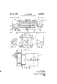
May 27, 1958 Filed Feb. 18, 1957 E. .1. ROMPRE ROOF DECK FABRICATING MECHANISM All.
CONVEYO 22 DECK TURNER 2 Sheets-Sheet TRIMMER Io TRIMMER couvevon I 2 0 +16 I l TONGl JE couvzvon AND CONVEYOR GROOVER INVENTOR.
ELMER J. ROMPRE BY omewwg United htates 2,836,282 Patented May v Eimer 3. Rompre, international Fails, Minn, assignor to Minnesota and @ntario Paper Company, viinneapoii Minn.
Application February 18, 1957, Serial No. 640,774
2 Ciaims. c1. 198-33) This invention relates to an apparatus for fabricating insulating roof material. 7 p
An important object of the invention is to provide an apparatus which permits fast and economical production of an insulating roof unit.
For the purpose of this invention there has been elected to set forth one particular structure but it is here presented for illustrative purposes only and is not to be accorded any interpretation such as might have the effect of limitin what is claimed as" the invention short of its true andcomprehensive scope in the art.
Other and further objects of the invention and the advantages of the same will be pointed out hereinafter and indicated in the appended claims or willbe obvious to one skilled in the art upon understanding the present disclosure.
in the drawings:
Figure l is a schematic diagram of the steps used in producing roof deck;
Figure 2 is an end view of part of the roof deck conveying apparatus;
Figure 3 is a side view of the roof deck turning apparatus;
Figure 4 is an end view of the device shown in Figure 3 with parts broken away;
Figure 5 is a top plan view of the apparatus shown in Figure 2 with parts broken away;
Figure 6 is a schematic view of the control circuit for one of the conveyors shown in Figure 5;
Figure 7 is a fragmentary view of a roof deck material that can be fabricated on the apparatus comprising the invention; and,
Figures 8 and 9 are schematic diagrams of fluid control circuits utilized in controlling parts of the conveying apparatus.
Fig. 10 shows details of a fluid transfer structure.
There is now being produced a roofing material which is being sold under the name of Insulite. Such product serves the purpose as decking, insulating and a finished interior ceiling. It is usually made of layers of insulating board laminated together with waterproof adhesive. One of the face surfaces is coated to present a finished ceiling surface. When such a product is to be used where the average January temperature is below F., a vapor barrier should be incorporated in the roof deck. The roof deck is fabricated in units generally about 2' X 8'. The joints formed by the adjacent units should be sealed to prevent the passage of vapor and this may be accomplished.
Roof slabs are generally made up of a plurality of fiberboards with a vapor barirer membrane between the board forming the finished ceiling surface and the adjacent board. The roof slabs are not less than about 1 /2 in thickness and may be as thick as about 3". Fiberboards are made up in slabs of a little larger than 8 X 8' with one face surface coated. This type of slab is divided into four units of about 2" in width and then trimmed to about'8 in length. This'dividing of the slab" into units is accomplished with the' coated surface up and saws or the like coming from the'under side: After the slabs are divided the units are/turned over so that the edges may be formed with a tongue on one side edge with the opposite side edge with a groove. At the time? the tongue is being formed, a groove is made adjacent the tongue-for the recep tion of an elastic member. Roof deck is usually fabricated with one surface coated to provide a finished ceiling surface. To prevent the fine ished surface from becoming marred; etc., the roof deck is turned during its manufacturei v Roof deck slabs with coated side up are transferred to trmimer conveyors 10 where the'slabs are divided longii tudinally into the desired width, the lengthwise divided' units are then cut to thedesired length by trimmer 12. The units 26, after leaving trimmer 12', slide down guide members 34 or board receiving means to limit-switch member 32. The units. are then discharged upon con} veyor 14 with the 'coatedsurface downwardly; From'the conveyor 14 the roof deck unitsare discharged to gravity conveyor 16 and then to roller supports mounted on 46. The supports lower the units 26' on to endless' chain conveyor 18. The units are moved through the tongue and groover anddischarged on to the deck turner 22 From the deck turner the units 26' are discharged on to conveyor 24. J i V n V V V I Roofde ck units 2 6, when discharged from trimmer 12 come into contact niember 32 which is"connectedto fluid control valve" 31. The fluid flows through line 37 to fluid cylinder 36 and results in the rod 38 operating member 4%. The member 40 is attached to rockable mounted member 42. Secured to member 42 are a series of pusher rods 44 which contact the deck unit 26 and result in turning the units. Upon the units 26 being discharged from the member 32 the fluid valve operates and the fluid flows through line 33 resulting in movement of rod 38 and associated parts to the inactive position.
The conveyor 14 may be of the endless type and includes two endless belts 72 operatively mounted on shafts 23 and 30. A switch 74 is mounted on the conveyor 14 so that the roof deck units contact the switch control means when passing along the conveyor. The conveyor 14 discharges the roof deck units on to conveyor 16 which carries the units to conveyor 18. When discharged from the conveyor 16 the units are received by spaced apart support arms 46. The support arms have mounted thereon covered rolls so that the finished ceiling surface is not damaged. The arms .6 are supported by pivotally mounted members and 52. These members 50 and 52 are connected by rod 54 so that movement of one results in an equal movement of the other arms. Fluid cylinder 58 is hingedly connected to the frame at 56 and piston rod 60 is connected to rod 64 at 62. The rod 64 is attached to arm member 52 at 66. When a roof deck unit strikes the control lever 76 the contact is closed and the fluid valve 68 opens which permits the fluid to flow through line 72. The fluid flowing through line 72 to cylinder moves rod 60 and results in the arm 46 folding downwardly in the direction of the traveling conveyor 18 to the position shown in Figure 5. The arms 46 are mounted so that they fold downwardly and deposit the roof deck unit on the conveyor 18 without damage to the surface thereof.
The conveyor 18 carries the units through the tongue and groover and discharges the units on to the deck turner 11 The glecl; t nner is nprmally locked against turningby bar 94 which has a projection which extends over e rid'barjfof thededi turner. The bar 94 is connected to bar 96 which is attached to frame 84 and has an upwardlvextending release bar hingedly attached to bar QKA' adjacentEiiiendQi Spring :nor mally urges the hf 94 to thellocked position as shown in Figure 3.
Mounted. onthe deck turner 22 are spaced rubber roils 8 6 on .Whic h theiunits 26 travel. On each corner of the decktturner'aremourited"a plurality of rubber rollers 88 which incooperation'vvit h the guard armsfifi insures that the Troofdeck unitsare properly? positioned on the turner 221" Atta ch ed toarms 90 and extending toward receiving '4 a What is claimed: r g 1. A board turnerfpositioned adjacent the discharge eiid of one conveyor and-adjacent the receiving end of eiidtof the turner are flat spring members 92. The spring a 92-I guide'sfth e board 26 so that it does not strike the arm a 90: when the "unit 26strikes: the upper end of bar 98 the bar 94, is forced from the locked position and the unitnpcsa'edavybrzag a thaLtheIoof deck units do not jam up on the cg'inveyOiLIS there is provided limit switches 74 and 78.
' whereifthfel-apparatu's isfidling, ;'svvitche s 74 and 78 are closed perihittingthefoperation of conveyor 14; When a ,rqdi deck unitr26fltrips switeh 74 the circuit'activating the ic ofiveyor'v 1.4 drive is still closed switch 78. If a roof deck units are placed in, the positions shown in Figure 5 thei'svvit ches .74? and 78 are open and the motor a llfoljdriving the conveyor 14 is stoppeduntil the roof deck'uziit ;suppo rted by arms 46 moves past themember' 75,"'.By;',thef arrangement just described units'f26 are prevented fromjamming' on the arms 46.
The, trimmers or conveyors may be of any suitable tfiinef-rotatesibnfqua rter turn'to dis ehar ge the root deck a typeandjthe' t'ypeshownin Patent No. 2,031,385, Figure 7 a' second conveyor, said secondconveyor positioned in a lower plane than the first mentioned conveyor, turner activating means mounted on the turner and engageablc 'by board thereon, cushioning rolls positioned on one side, of a board receiving surface," a guard arm positioned on p the opposite side; of the board receivingt surface, and means for locking the board receiving surface in posi;
tion so aboard can be discharged thereon from thefi'rs t- I mentioned conveyor. I
. 2. A board turner of the drum type having four board" receiving surfaces, meansf along the edges of'each board receiving surface to assist in positioning board on the receiving surfaces, 'a shaft supported by the turner, means for turning the shaft, locking means for holding a board receiving surface in position to receive a board, a lever for releasing the locking means, said lever engageable by a board on the turner, and means for locking second} board receiving surface 'in position upon the'turning of the V. V A V References Cited inlthe file foi? napalm; 5 UNITED STATES PATENTS 912,764 Wintgens Feb. 16, 1909 1,446,851 Littleford Feb; 27, 1923 1,929,204 Jeffrey Oct. 3, 1933,, 1,943,530 Hoefiieur Jan. 16, 1934 2,029,456 7 Zuber Feb. 4,- 1936 2,434,411 JOhnSOn'm: Jan.*'13,' 2,659,475 Archer' Nov. 17, 1953B 2,732,057 Temple Jan. 24, 1956' 2,784,831
Connell Mar. :12, 195-7
Priority Applications (1)
| Application Number | Priority Date | Filing Date | Title |
|---|---|---|---|
| US640774A US2836282A (en) | 1957-02-18 | 1957-02-18 | Roof deck fabricating mechanism |
Applications Claiming Priority (1)
| Application Number | Priority Date | Filing Date | Title |
|---|---|---|---|
| US640774A US2836282A (en) | 1957-02-18 | 1957-02-18 | Roof deck fabricating mechanism |
Publications (1)
| Publication Number | Publication Date |
|---|---|
| US2836282A true US2836282A (en) | 1958-05-27 |
Family
ID=24569654
Family Applications (1)
| Application Number | Title | Priority Date | Filing Date |
|---|---|---|---|
| US640774A Expired - Lifetime US2836282A (en) | 1957-02-18 | 1957-02-18 | Roof deck fabricating mechanism |
Country Status (1)
| Country | Link |
|---|---|
| US (1) | US2836282A (en) |
Cited By (2)
| Publication number | Priority date | Publication date | Assignee | Title |
|---|---|---|---|---|
| US3595366A (en) * | 1969-05-13 | 1971-07-27 | Safeway Stores | Conveyer structure for packaging machines |
| DE102020006799A1 (en) | 2020-11-05 | 2022-05-05 | Grenzebach Bsh Gmbh | Device for turning panels |
Citations (9)
| Publication number | Priority date | Publication date | Assignee | Title |
|---|---|---|---|---|
| US912764A (en) * | 1908-06-22 | 1909-02-16 | Peter J Wintgens | Cooling device for tin-sheet mills. |
| US1446851A (en) * | 1921-08-18 | 1923-02-27 | Littleford George | Woodworking mechanism |
| US1929204A (en) * | 1931-12-09 | 1933-10-03 | Universal Gypsum & Lime Co | Transfer means for board machines |
| US1943530A (en) * | 1931-05-25 | 1934-01-16 | Standard Oil Co | Barrel handling machinery |
| US2029456A (en) * | 1931-04-16 | 1936-02-04 | Robert B Zuber | Tripping mechanism |
| US2434411A (en) * | 1945-12-28 | 1948-01-13 | Elliott Bay Mill Co | Selective transfer apparatus for plywood |
| US2659475A (en) * | 1950-02-03 | 1953-11-17 | Campbell Taggart Res Corp | Pan turning mechanism |
| US2732057A (en) * | 1956-01-24 | Bakery conveyor system | ||
| US2784831A (en) * | 1954-02-16 | 1957-03-12 | J B Ehrsam & Sons Mfg Company | Automatic inverter |
-
1957
- 1957-02-18 US US640774A patent/US2836282A/en not_active Expired - Lifetime
Patent Citations (9)
| Publication number | Priority date | Publication date | Assignee | Title |
|---|---|---|---|---|
| US2732057A (en) * | 1956-01-24 | Bakery conveyor system | ||
| US912764A (en) * | 1908-06-22 | 1909-02-16 | Peter J Wintgens | Cooling device for tin-sheet mills. |
| US1446851A (en) * | 1921-08-18 | 1923-02-27 | Littleford George | Woodworking mechanism |
| US2029456A (en) * | 1931-04-16 | 1936-02-04 | Robert B Zuber | Tripping mechanism |
| US1943530A (en) * | 1931-05-25 | 1934-01-16 | Standard Oil Co | Barrel handling machinery |
| US1929204A (en) * | 1931-12-09 | 1933-10-03 | Universal Gypsum & Lime Co | Transfer means for board machines |
| US2434411A (en) * | 1945-12-28 | 1948-01-13 | Elliott Bay Mill Co | Selective transfer apparatus for plywood |
| US2659475A (en) * | 1950-02-03 | 1953-11-17 | Campbell Taggart Res Corp | Pan turning mechanism |
| US2784831A (en) * | 1954-02-16 | 1957-03-12 | J B Ehrsam & Sons Mfg Company | Automatic inverter |
Cited By (2)
| Publication number | Priority date | Publication date | Assignee | Title |
|---|---|---|---|---|
| US3595366A (en) * | 1969-05-13 | 1971-07-27 | Safeway Stores | Conveyer structure for packaging machines |
| DE102020006799A1 (en) | 2020-11-05 | 2022-05-05 | Grenzebach Bsh Gmbh | Device for turning panels |
Similar Documents
| Publication | Publication Date | Title |
|---|---|---|
| US1737762A (en) | Conveyer | |
| JPH05338774A (en) | Flip sliding device | |
| BR9607947A (en) | Apparatus and method for turning and positioning articles | |
| US4040618A (en) | Sheet stacking apparatus | |
| WO2014186175A1 (en) | Method and conveyor for registering articles on a conveyor belt | |
| US3207017A (en) | Method and apparatus for trimming and splitting double books into separate books | |
| US4602466A (en) | Foam building panels | |
| US3269516A (en) | Sheet turning mechanism | |
| US2667259A (en) | Sheet handling apparatus | |
| US3172372A (en) | Method and apparatus for the rolling of materials | |
| US2829759A (en) | Sheet handling apparatus | |
| CA2879611C (en) | V groove insulation machine | |
| US2836282A (en) | Roof deck fabricating mechanism | |
| KR101837138B1 (en) | Apparatus for cutting styrofoam | |
| US3195710A (en) | Equipment for arranging packages | |
| US3034632A (en) | Sheet handling apparatus | |
| US2422726A (en) | Bottle conveyor | |
| US2963143A (en) | Apparatus for handling articles | |
| US3622150A (en) | Sheet conveying and stacking apparatus | |
| GB1205654A (en) | Apparatus for transporting plate-shaped workpieces | |
| US2644496A (en) | Edge gluing device | |
| US1567289A (en) | Machine for cutting sheets into suitable lengths and widths | |
| GB2044712A (en) | Apparatus for Changing the Orientation of Articles on a Conveyor | |
| US3937342A (en) | Apparatus for opening and unloading cartons | |
| JPS6194916A (en) | Transported article aligning apparatus |