US2836070A - Damping mechanism - Google Patents
Damping mechanism Download PDFInfo
- Publication number
- US2836070A US2836070A US583692A US58369256A US2836070A US 2836070 A US2836070 A US 2836070A US 583692 A US583692 A US 583692A US 58369256 A US58369256 A US 58369256A US 2836070 A US2836070 A US 2836070A
- Authority
- US
- United States
- Prior art keywords
- piston
- cylinder
- damping
- frame
- arcuate
- Prior art date
- Legal status (The legal status is an assumption and is not a legal conclusion. Google has not performed a legal analysis and makes no representation as to the accuracy of the status listed.)
- Expired - Lifetime
Links
- 238000013016 damping Methods 0.000 title description 41
- 230000007246 mechanism Effects 0.000 title description 17
- 230000035939 shock Effects 0.000 description 8
- 230000010355 oscillation Effects 0.000 description 7
- 239000006096 absorbing agent Substances 0.000 description 4
- 230000009471 action Effects 0.000 description 4
- 230000002093 peripheral effect Effects 0.000 description 4
- 230000006835 compression Effects 0.000 description 3
- 238000007906 compression Methods 0.000 description 3
- 230000008030 elimination Effects 0.000 description 2
- 238000003379 elimination reaction Methods 0.000 description 2
- 239000012530 fluid Substances 0.000 description 2
- 239000007788 liquid Substances 0.000 description 2
- 230000003534 oscillatory effect Effects 0.000 description 2
- 230000004044 response Effects 0.000 description 2
- VQKFNUFAXTZWDK-UHFFFAOYSA-N alpha-methylfuran Natural products CC1=CC=CO1 VQKFNUFAXTZWDK-UHFFFAOYSA-N 0.000 description 1
- 238000010276 construction Methods 0.000 description 1
- MXCPYJZDGPQDRA-UHFFFAOYSA-N dialuminum;2-acetyloxybenzoic acid;oxygen(2-) Chemical compound [O-2].[O-2].[O-2].[Al+3].[Al+3].CC(=O)OC1=CC=CC=C1C(O)=O MXCPYJZDGPQDRA-UHFFFAOYSA-N 0.000 description 1
- 230000000694 effects Effects 0.000 description 1
- 210000003414 extremity Anatomy 0.000 description 1
- 238000003754 machining Methods 0.000 description 1
- 230000004048 modification Effects 0.000 description 1
- 238000012986 modification Methods 0.000 description 1
- 229920000136 polysorbate Polymers 0.000 description 1
- 230000000452 restraining effect Effects 0.000 description 1
- 210000000707 wrist Anatomy 0.000 description 1
Images


Classifications
-
- F—MECHANICAL ENGINEERING; LIGHTING; HEATING; WEAPONS; BLASTING
- F16—ENGINEERING ELEMENTS AND UNITS; GENERAL MEASURES FOR PRODUCING AND MAINTAINING EFFECTIVE FUNCTIONING OF MACHINES OR INSTALLATIONS; THERMAL INSULATION IN GENERAL
- F16F—SPRINGS; SHOCK-ABSORBERS; MEANS FOR DAMPING VIBRATION
- F16F15/00—Suppression of vibrations in systems; Means or arrangements for avoiding or reducing out-of-balance forces, e.g. due to motion
- F16F15/02—Suppression of vibrations of non-rotating, e.g. reciprocating systems; Suppression of vibrations of rotating systems by use of members not moving with the rotating systems
- F16F15/023—Suppression of vibrations of non-rotating, e.g. reciprocating systems; Suppression of vibrations of rotating systems by use of members not moving with the rotating systems using fluid means
-
- Y—GENERAL TAGGING OF NEW TECHNOLOGICAL DEVELOPMENTS; GENERAL TAGGING OF CROSS-SECTIONAL TECHNOLOGIES SPANNING OVER SEVERAL SECTIONS OF THE IPC; TECHNICAL SUBJECTS COVERED BY FORMER USPC CROSS-REFERENCE ART COLLECTIONS [XRACs] AND DIGESTS
- Y10—TECHNICAL SUBJECTS COVERED BY FORMER USPC
- Y10T—TECHNICAL SUBJECTS COVERED BY FORMER US CLASSIFICATION
- Y10T74/00—Machine element or mechanism
- Y10T74/12—Gyroscopes
- Y10T74/1229—Gyroscope control
- Y10T74/1257—Damping
Definitions
- This invention relates to improvements in damping devices of the type employing a cylinder, a piston slidably mounted therein and a piston rod connected thereto and to the object whose movement it is desired to be damped.
- the invention relates to improvements in this type of damping device that employs a substantially spherical, or arcuate, piston that is slidable with close tolerances in the cylinder, as distinguishes from the conventional cylindrical type of piston, in order to gain the advantages of universal movement of the spherical, or axially arcuate piston within the cylinder so as to avoid the necessity of extensive linkages and yielding connections between the piston and the object whose movements it is desired to be damped.
- a movement of the piston upwardly, in response to a shock to the axle in an upward direction, results in a compression of air in the cylinder between the piston and the valve.
- this compression reaches a predetermined degree, the valve is lifted to open the vent to atmosphere, permitting free motion of the piston during the remainder of its upward stroke.
- the piston Upon rebound, the piston will be drawn downwardly, permitting the spring to force the valve down in the cylinder past the level of the vent.
- a shock absorber but not a device that is capable of performing as a device for at all times uniformly damping all of the movements of the piston within the cylinder in all directions in response to such movements of the device whose movements it is desired to be damped.
- Another, and extremely important object of the invention is to provide in such a damping mechanism, means whereby all movements of the object to be damped in any direction are at all times damped.
- the cylinder will be 2,836,070 Patented May 27, 1958 referred to as having a permanently closed head.
- the fluid between the piston and the cylinder head may be gaseous or liquid.
- piston By referring to our piston as being axially arcuate, or substantially spherical in form, we mean to imply that that portion of the periphery of the piston that comes in contact with the inner surface of the cylinder is arcuate, or substantially spherical. vIt is not necessary that the remainder of the piston be truly spherical, or arcuate, in form.
- substantially spherical and axially arcuate are used to describe the periphery of the piston, they are intended to be interchangeable in meaning, and not intended to be restricted necessarily to a true geometrical sphere, but to include an axially arcuate periphery with respect to its axial plane of stroke in the cylinder and to distinguish over a cylindrical piston for the hereinabove advantageous purposes.
- the invention relates to improvements in damping controls for instruments having an element which is movable in a limited orbital path.
- an object of the invention is to provide an improved damping mechanism that will be suitable for use as a damping control for flight instruments.
- a more specific object of this invention is to provide an improved damping control for an aircraft flight instrument of the gyro type, wherein eifective damping is maintained on the gimbal ring in which the gyro is mounted.
- Another object of this invention is to provide an improved damping control for an aircraft flight instrument of the gyro stabilized type, wherein effective damping is maintained on the gyro mounting gimbal which is movable in a limited orbital path to prevent undesirable oscillations of the indicating needle of such an instrument.
- a further object of this invention is to provide an improved damping control structure associated with a body movable in a limited orbital path to prevent undesirable oscillations of the body.
- Still another object of this invention is to provide an improved damping control structure of the piston type connected with a body movable in a limited orbital path to prevent undesirable oscillations of the body.
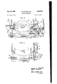
- Figure l is a view in side elevation of an instrument to which the invention is applied with the outer casing removed;
- Figure 2 is a plan view of the Figure 1;
- Figure 3 is a sectional view along the line 33 of Figure 2;
- Figure 4 is a sectional View in side elevation taken along the lines 4-4 of Figure 2;
- Figure 5 is a partially sectioned view in front elevation taken along the lines 5-5 of Figure 1;
- Figure 6 is a view in partial section similar to Figure 5 instrument illustrated in in side elevation taken i but illustrating the damping I the "cylinders "therefor, 'cut away for clarity;
- I are connected coil restraining springs 19 and 11.
- control pistons in Figure 7 is a view in frontelevation of the instrument of FigureL illustrating the indicating structure of the v instrument.
- Figure 3 is a partially sectional view in front elevation taken along the lines :8-8 of Figure 1.
- This invention is particularly suitable for aircraftin strurnents of the slip and turn type, but is equally adaptable to useindamping out oscillations inany body, especially a body that is mounted to move in a limited orbital path. 'However, for. purposes of'desciiptionof the invention and its operationflhis specification will describe its adaptability to slip and turn indicators as stabilizedby gyros.
- a slip andturn indicator is illustrated with its casing removed as having an instrument dial '1, connected by screws 2, to forwardly projecting studs 3,of supporting frame 4.
- a gimbal ring 5 is mounted within frame 4 byibearings 6 and 7 along the longitudinal axis of the instrument.
- Positioned on either side of bearing 7 and depending from gimbal ring 5 is'a pair of arms 8 and 9.
- the other ends of springs 10 and 11 are connected tothe rear end of frame '4 by being secured in plugsIZ that l are press fit into frame 4.
- theend 13 of spring 10 is illustrated as projecting through a plug 12', and being bent overat the exterior of'the plug.
- Clamped to bearing 7 is 'asplitcrank member 21, which is secured to the hearing by tightening a clampingscrew 22.
- Extending forwardly of member 21 and secured therein by a pressed fit or other suitable means is a pin 23. Pin 23 engages a U-shaped slot 24 in rocker, arm
- member 25 is supported for free rotation by a ntifriction bearings 26 on a stud 27 which itself is supported by frame 4.
- the stud 27 acts as a stop and is provided with a resilient'sleeve 28to absorb the shock of arms 8 and 9 contacting the same when springs 10 and 11 fail to constrain the gimbal, and a positive limit stop is desired in either direction of .movetnent.
- the rocker arm member-'25 is provided with arms 29 and 30 extending to either side of its bearing support. Near the extremity of each arm 29 and 36 there are provided holes 31 and 32 respectively to accommodate, in pressed fit relationship, wrist pins 33 and 34. About-the reduced portion 35, of each pin 33 and 34 aremounted the ends of pistonrods 36 and 37, the former being rigidly connected in any suitable manner to piston 19 and the latter rigidly connected to piston 26.
- the bores of cylinders 16 and 17 are precision machined.
- the peripheral walls of pistons 19 and ZO are likewise precision machined 'to have a snug, free, sliding fit with the cylinder bores. Since the cylinders be- .tween the pistons and the heads 38 and 39 of the cylin ders 16 and 17 are not provided with outlets for air, .1 considerable dash-pot or damping, action is obtained by the arrangement,asdistinguished from merely a shock absorbing action.
- the peripheral surfaces of the pistons are'essentially of spheriv cal, or-arcuate, form. T he pistons may be spherical,.-but
- r 4.; V are shown flattened at the top and bottom with the midportionsisphericalij I" I Secured to the'upper front surface of member 25 is a mounting block 46 having a forwardly extending pin 41 threaded therein.
- the pin 41 extends through a slot 42 in dial l and fixedlyccarries a pointer 43 thereon. Thus any movement of member 25 is transmitted to pointer 43.
- the gyro mountedin'bearings 45' on gimbal ring .5 will precess relative ;to.the speed or rate of the turn and indicate this to the pilot by action of the pointer- 43 as controlled by the movementof the rocker arm member 2'5s whieh is responsive to gimbal ring movement.
- the pointer 43 is damped by the piston and cylinder arrangementnof the invention in either direction of orbital movement by the gimbal '5.
- the invention provides a novel, simple and improved damping control. for a slip and;
- a'damping device that employs a substantially sphericahor arcuate, piston that is slidable withclose tolerances in the cylinder, as dis-; tinguished from the conventional cylindrical type of' pistomin order to gain the advantages of universalmovement of the sphericalpiston within the cylinder in order 7 to. avoid the inecessity of extensive linkages and yield-J ing connections between the pistonandtthe object whose movements it is desired to be damped.
- a damping mechanism that includes a cylinder carried by a frame member and an arcuate or substantially spherical piston slidable withi close tolerances in the cylinder and a piston rod rigidly secured to the piston and the object'to be damped by non-yielding connectionsto obtain the advantages of the universalmovement of the spherical, or arcuate, piston within the cylinder and the elimination of yielding connections and linkages between the cylinder and the object to he damped in its movements. 7
- a damping mechanism for damping the movements of a member mounted in a frame for limited orbital movement relative thereto comprising a cylinder having a permanently closed head and carried by said frame, drive means including an arm carried by said member and a lever connected to said arm to be oscillated thereby, a pin secured to said frame and upon which said lever is mounted, said pin constituting a stop to limit orbital movement of said member in both directions, a piston slidably mounted in said cylinder and a piston rod rigidly secured to said piston against relative movement, said piston being spherical in form in so far as that portion of the peripheral surface of said piston which engages the inner surface of said cylinder is concerned to afiord universal movement of said piston in said cylinder, said piston rod being directly connected to said lever to be actuated thereby to damp the movements of said member.
- a damping mechanism for an aircraft flight instrument including a frame, a gimbal ring carried by bearings on said frame and a gyro rotatably mounted within said gimbal ring to be supported thereby, said damping mechanism comprising a pair of opposed damping units, each damping unit including a cylinder having a permanently closed head and carried by said frame,
- a damping mechanism for an aircraft instrument including a dial, a pointer, a frame, a gimbal ring carried by bearings on said frame and a gyro rotatably mounted within said frame to be supported thereby, said damping mechanism including a pair of opposed damping units, each of said damping units including a cylinder having a permanently closed head and carried by said frame, a piston slidably mounted in said cylinder and a piston rod secured to said piston, drive means including an arm directly connected to said gimbal ring and a lever connected to said arm to be oscillated thereby, a pin secured to said frame and upon which said lever is mounted, said pin constituting a stop to limit oscillatory movement of said gimbal ring in both directions, said lever being connected to said pointer to support and drive the same, said piston rods being directly connected to said lever to effect a damping control back through said lever and arm to said gyro and to said pointer to minimize oscillations thereof.
Landscapes
- Engineering & Computer Science (AREA)
- General Engineering & Computer Science (AREA)
- Physics & Mathematics (AREA)
- Acoustics & Sound (AREA)
- Aviation & Aerospace Engineering (AREA)
- Mechanical Engineering (AREA)
- Fluid-Damping Devices (AREA)
Description
May 27, 1958 J. R. STOKES EI'AL 2,836,070
DAMPING MECHANISM .Filed May 9, 1956 3 Sheets-Sheet 1 IN VEN TORS JEFFREY R. Eli RED M. SPRINGE ATTORNEY M y 1958 J. R. STOKES EI'AL 2,836,070
DAMPING MECHANISM Filed May 9, 1956 3 Sheets-Sheet 2 FIG. 3 5
I. van"...
INVENTORS 1 JEFFREY R. STOKES 8 F550 M. SPRINGER il/W ATTORNEY May 27, 1 J. R. STOKES EIAL DAMPING MECHANISM 3 SheetsSheet'3 Filed May 9, 1956 FIG. 8
FIG. 7
M. SPRINGER ATTORNEY United States Patent DAMPING MECHANISM Jeffrey R. Stokes, Delmar, and Fred M. Springer, Solana Beach, Calif., assignors to Bill Jack Scientific InstrL- nent Co., Solana Beach, Calif., a corporation of Caliornia Application May 9, 1956, Serial No. 583,692
3 Claims. (Cl. 745.5)
This invention relates to improvements in damping devices of the type employing a cylinder, a piston slidably mounted therein and a piston rod connected thereto and to the object whose movement it is desired to be damped.
More specifically, the invention relates to improvements in this type of damping device that employs a substantially spherical, or arcuate, piston that is slidable with close tolerances in the cylinder, as distinguishes from the conventional cylindrical type of piston, in order to gain the advantages of universal movement of the spherical, or axially arcuate piston within the cylinder so as to avoid the necessity of extensive linkages and yielding connections between the piston and the object whose movements it is desired to be damped.
We are fully aware of the existence of the United States Letters Patent to Young, 1,254,106, for Shock Absorber, January 22, 1918. This patent discloses a shock absorbing cylinder and a spherical, or axially arcuate piston slidable therein, the cylinder being connected to a vehicle body and the piston rod being connected by a yielding connection to the vehicle axle. Near the upper portion of the cylinder there is provided a vent aperture to atmosphere. To the upper closed head of the cylinder is secured a compression coil spring that urges a valve downwardly in the cylinder normally to a position below the vent. Thus, a movement of the piston upwardly, in response to a shock to the axle in an upward direction, results in a compression of air in the cylinder between the piston and the valve. When this compression reaches a predetermined degree, the valve is lifted to open the vent to atmosphere, permitting free motion of the piston during the remainder of its upward stroke. Upon rebound, the piston will be drawn downwardly, permitting the spring to force the valve down in the cylinder past the level of the vent. This is, in a true sense, a shock absorber, but not a device that is capable of performing as a device for at all times uniformly damping all of the movements of the piston within the cylinder in all directions in response to such movements of the device whose movements it is desired to be damped.
It is therefore one of the primary objects of this invention to provide a damping mechanism that includes a cylinder carried by a frame member and an axially arcuate, or substantially spherical, piston slidable with close tolerances in the cylinder and a piston rod rigidly secured to the piston and the object to be damped by non-yielding connections to obtain the advantages of the universal movement of the spherical, or axially arcuate, piston within the cylinder and the elimination of yielding connections and linkages between the cylinder and the object whose movements it is desired to be damped.
Another, and extremely important object of the invention is to provide in such a damping mechanism, means whereby all movements of the object to be damped in any direction are at all times damped.
More specifically, we propose to employ a substantially spherical, or axially arcuate, ball slidably mounted, with close tolerances, in a cylinder.
The cylinder will be 2,836,070 Patented May 27, 1958 referred to as having a permanently closed head. By this we mean to imply that we employ no cylinder vents, valves or springs. The fluid between the piston and the cylinder head may be gaseous or liquid. Thus, regardless of the position of the piston in the cylinder, whether at rest or during any upward or downward stroke of the piston in the cylinder, at any time, it is necessary at all times that a positive force in an upward or downward direction he applied to the piston, through its piston rod from the object to be damped, and against a uniform resistance, in order to cause any upward or downward movement of the piston relative to the cylinder. It is this characteristic that renders our damping mechanism a true damper, in addition to being a shock absorber. By referring to our piston as being axially arcuate, or substantially spherical in form, we mean to imply that that portion of the periphery of the piston that comes in contact with the inner surface of the cylinder is arcuate, or substantially spherical. vIt is not necessary that the remainder of the piston be truly spherical, or arcuate, in form. Moreover, hereinafter, when the terms substantially spherical and axially arcuate are used to describe the periphery of the piston, they are intended to be interchangeable in meaning, and not intended to be restricted necessarily to a true geometrical sphere, but to include an axially arcuate periphery with respect to its axial plane of stroke in the cylinder and to distinguish over a cylindrical piston for the hereinabove advantageous purposes.
More specifically, the invention relates to improvements in damping controls for instruments having an element which is movable in a limited orbital path.
Accordingly, an object of the invention is to provide an improved damping mechanism that will be suitable for use as a damping control for flight instruments.
A more specific object of this invention is to provide an improved damping control for an aircraft flight instrument of the gyro type, wherein eifective damping is maintained on the gimbal ring in which the gyro is mounted.
Another object of this invention is to provide an improved damping control for an aircraft flight instrument of the gyro stabilized type, wherein effective damping is maintained on the gyro mounting gimbal which is movable in a limited orbital path to prevent undesirable oscillations of the indicating needle of such an instrument.
A further object of this invention is to provide an improved damping control structure associated with a body movable in a limited orbital path to prevent undesirable oscillations of the body.
Still another object of this invention is to provide an improved damping control structure of the piston type connected with a body movable in a limited orbital path to prevent undesirable oscillations of the body.
With the foregoing and other objects in view, the invention resides in the combination of parts and in the details of construction hereinafter set forth in the following specification and appended claims, certain embodiments of which are illustrated in the accompanying drawings in winch:
Figure l is a view in side elevation of an instrument to which the invention is applied with the outer casing removed;
Figure 2 is a plan view of the Figure 1;
Figure 3 is a sectional view along the line 33 of Figure 2;
Figure 4 is a sectional View in side elevation taken along the lines 4-4 of Figure 2;
Figure 5 is a partially sectioned view in front elevation taken along the lines 5-5 of Figure 1;
Figure 6 is a view in partial section similar to Figure 5 instrument illustrated in in side elevation taken i but illustrating the damping I the "cylinders "therefor, 'cut away for clarity;
I are connected coil restraining springs 19 and 11.
control pistons in Figure 7 is a view in frontelevation of the instrument ofFigureL illustrating the indicating structure of the v instrument; and
Figure 3 is a partially sectional view in front elevation taken along the lines :8-8 of Figure 1.
This invention is particularly suitable for aircraftin strurnents of the slip and turn type, but is equally adaptable to useindamping out oscillations inany body, especially a body that is mounted to move in a limited orbital path. 'However, for. purposes of'desciiptionof the invention and its operationflhis specification will describe its adaptability to slip and turn indicators as stabilizedby gyros.
Referring now more particularly tofthe drawings, a slip andturn indicator is illustrated with its casing removed as having an instrument dial '1, connected by screws 2, to forwardly projecting studs 3,of supporting frame 4. f Mounted within frame 4, which is fixed relative' to 'the case, not shown, is a gimbal ring 5. Gimbal ring 5 is supported within frame 4 byibearings 6 and 7 along the longitudinal axis of the instrument. Positioned on either side of bearing 7 and depending from gimbal ring 5 is'a pair of arms 8 and 9. To the end of each arm The other ends of springs 10 and 11 are connected tothe rear end of frame '4 by being secured in plugsIZ that l are press fit into frame 4. in Figure. 4 theend 13 of spring 10 is illustrated as projecting through a plug 12', and being bent overat the exterior of'the plug. The
action, with springs limit the orbital movement or. oscillation limitsof the gimbal ring aboutits bearing axis.
Connected to frame 4 by means of clamp 14 and .screw 15, are damping control cylinders 16 and 17. The bearing 7, which is connected for movement with gimbal 5 by a press fit'pin18, projects beyond casing 4 toprovide a drive structure for the operating damping pistons 19 and 20 s'lidably mounted in cylinders l6 and 17. Clamped to bearing 7 is 'asplitcrank member 21, which is secured to the hearing by tightening a clampingscrew 22. Extending forwardly of member 21 and secured therein by a pressed fit or other suitable means is a pin 23. Pin 23 engages a U-shaped slot 24 in rocker, arm
The bores of cylinders 16 and 17 are precision machined. The peripheral walls of pistons 19 and ZO are likewise precision machined 'to have a snug, free, sliding fit with the cylinder bores. Since the cylinders be- .tween the pistons and the heads 38 and 39 of the cylin ders 16 and 17 are not provided with outlets for air, .1 considerable dash-pot or damping, action is obtained by the arrangement,asdistinguished from merely a shock absorbing action. In order to secure a universal freedom between the pistons and the cylinder bores, the peripheral surfaces of the pistons are'essentially of spheriv cal, or-arcuate, form. T he pistons may be spherical,.-but
r 4.; V are shown flattened at the top and bottom with the midportionsisphericalij I" I Secured to the'upper front surface of member 25 is a mounting block 46 having a forwardly extending pin 41 threaded therein. The pin 41 extends through a slot 42 in dial l and fixedlyccarries a pointer 43 thereon. Thus any movement of member 25 is transmitted to pointer 43.
In operation as .the aircraft carrying the instrument of this invention turns, the gyro mountedin'bearings 45' on gimbal ring .5 will precess relative ;to.the speed or rate of the turn and indicate this to the pilot by action of the pointer- 43 as controlled by the movementof the rocker arm member 2'5s whieh is responsive to gimbal ring movement. .Movementpf the pointer 43 is damped by the piston and cylinder arrangementnof the invention in either direction of orbital movement by the gimbal '5. The pistons 19 and2t). of this invention :allowihe gyro to return to a vertical posiiionfast enough .to .be within the timettolerance required formost aeronautical purposes but allow no over travel or oscillation of pointer 43. Since no bleed valves are provided in the, cylinders between the pistons and the cylinder heads, .the only escape of air must "be from one side of the piston to the other when any orbital movement occurs. Thus, a predetermined damping .efiect mayflbe'achievedbyad boring to close machining tolerances of the piston axially arcuate surfaces and the cylinder bores.
V In Figure -1 the standard .type .of .slip' indicator 46 is shown carried by thebottom portion of diall, On the rear of frame 4 is mounted a'radio interference .elimi-. V
this invention and hence they have not beendescribed in' detail.
Thus, it willbe seen that the invention provides a novel, simple and improved damping control. for a slip and;
turnindicator or other instrument having an element with a limited orbital .movement. .Moreover, various modifications of thisinvention,.particularlyin the damp- Within the purview of the ing drive linkage may bemade invention. 7
Moreover, we have provided a'damping device that employs a substantially sphericahor arcuate, piston that is slidable withclose tolerances in the cylinder, as dis-; tinguished from the conventional cylindrical type of' pistomin order to gain the advantages of universalmovement of the sphericalpiston within the cylinder in order 7 to. avoid the inecessity of extensive linkages and yield-J ing connections between the pistonandtthe object whose movements it is desired to be damped.
We have also provided a damping mechanism that includes a cylinder carried by a frame member and an arcuate or substantially spherical piston slidable withi close tolerances in the cylinder and a piston rod rigidly secured to the piston and the object'to be damped by non-yielding connectionsto obtain the advantages of the universalmovement of the spherical, or arcuate, piston within the cylinder and the elimination of yielding connections and linkages between the cylinder and the object to he damped in its movements. 7
We have also provided in such a dampingmec'hanism, means whereby all-movements of the object to be'damped in any direction are at a l times damped. I More specifically, we have provided a substantially spherical, or arcuate, ball slidably mounted, with close tolerances,.in acylinder. The cylinder has been referred vto as having a permanently closed head. By this we mean to imply thatwe=employ no cylinder vents, .valves or springs. The fluid between the pistonand the cylinder head may be gaseous or liquid. .Thus regardless ofithe position of the piston-in the cylinder, whether atrestor .during any upwardordownwardstroke of thenpistomin thetcyliudengatiany-time, it1is:necessaryatmllitimes that a positive force in an upward or downward direction be applied to the piston through its piston rod from the object to be damped, and against a uniform resistance, in order to cause any upward or downward movement of the piston relative to the cylinder. It is this characteristic that renders our damping mechanism a true damper, in addition to being a shock absorber. By referring to our piston as being arcuate, or substantially spherical in form, we mean to imply that that portion of the periphery of the piston that comes in contact with the inner surface of the cylinder is arcuate, or substantially spherical. It is not necessary that the remainder of the piston be truly spherical, or arcuate, in form. Moreover, hereinafter, when the terms substantially spherical and arcuate are used to describe the periphery of the piston, they are intended to be interchangeable in meaning, as not intended to be restricted necessarily to a true geometrical sphere, but to be arcuate and to distinguish over a cylindrical piston for the hereinabove advantageous purposes.
We claim:
1. A damping mechanism for damping the movements of a member mounted in a frame for limited orbital movement relative thereto, said damping mechanism comprising a cylinder having a permanently closed head and carried by said frame, drive means including an arm carried by said member and a lever connected to said arm to be oscillated thereby, a pin secured to said frame and upon which said lever is mounted, said pin constituting a stop to limit orbital movement of said member in both directions, a piston slidably mounted in said cylinder and a piston rod rigidly secured to said piston against relative movement, said piston being spherical in form in so far as that portion of the peripheral surface of said piston which engages the inner surface of said cylinder is concerned to afiord universal movement of said piston in said cylinder, said piston rod being directly connected to said lever to be actuated thereby to damp the movements of said member.
2. A damping mechanism for an aircraft flight instrument including a frame, a gimbal ring carried by bearings on said frame and a gyro rotatably mounted within said gimbal ring to be supported thereby, said damping mechanism comprising a pair of opposed damping units, each damping unit including a cylinder having a permanently closed head and carried by said frame,
a piston slidably mounted in said cylinder and a piston rod rigidly secured to said piston against relative movement, said piston being spherical in form in so far as that portion of the peripheral surface of said piston which engages the inner surface of said cylinder is concerned to afford universal movement of said piston in said cylinder, drive means including an arm directly connected to said gimbal ring and a lever connected to said arm to be oscillated thereby, a pin secured to said frame and upon which said lever is mounted, said pin constituting a stop to limit oscillatory movement of said gimbal ring in both directions, said piston rods being directly connected to said lever to be actuated thereby to damp the movements of the axis of said gyro.
3. A damping mechanism for an aircraft instrument including a dial, a pointer, a frame, a gimbal ring carried by bearings on said frame and a gyro rotatably mounted within said frame to be supported thereby, said damping mechanism including a pair of opposed damping units, each of said damping units including a cylinder having a permanently closed head and carried by said frame, a piston slidably mounted in said cylinder and a piston rod secured to said piston, drive means including an arm directly connected to said gimbal ring and a lever connected to said arm to be oscillated thereby, a pin secured to said frame and upon which said lever is mounted, said pin constituting a stop to limit oscillatory movement of said gimbal ring in both directions, said lever being connected to said pointer to support and drive the same, said piston rods being directly connected to said lever to effect a damping control back through said lever and arm to said gyro and to said pointer to minimize oscillations thereof.
References Cited in the file of this patent UNITED STATES PATENTS 1,330,501 Tanner Feb. 10, 1920 2,242,253 Lyman May 20, 1941 2,444,625 Bevins July 6, 1948 2,709,921 Sylvan June 7, 1955 FOREIGN PATENTS 340,327 Great Britain Jan. 1, 1931 387,366 Great Britain Jan. 30, 1933
Priority Applications (1)
| Application Number | Priority Date | Filing Date | Title |
|---|---|---|---|
| US583692A US2836070A (en) | 1956-05-09 | 1956-05-09 | Damping mechanism |
Applications Claiming Priority (1)
| Application Number | Priority Date | Filing Date | Title |
|---|---|---|---|
| US583692A US2836070A (en) | 1956-05-09 | 1956-05-09 | Damping mechanism |
Publications (1)
| Publication Number | Publication Date |
|---|---|
| US2836070A true US2836070A (en) | 1958-05-27 |
Family
ID=24334178
Family Applications (1)
| Application Number | Title | Priority Date | Filing Date |
|---|---|---|---|
| US583692A Expired - Lifetime US2836070A (en) | 1956-05-09 | 1956-05-09 | Damping mechanism |
Country Status (1)
| Country | Link |
|---|---|
| US (1) | US2836070A (en) |
Cited By (2)
| Publication number | Priority date | Publication date | Assignee | Title |
|---|---|---|---|---|
| US3142181A (en) * | 1964-07-28 | Moller | ||
| US3307413A (en) * | 1963-09-16 | 1967-03-07 | Lear Siegler Inc | Magnetically switched gyro |
Citations (6)
| Publication number | Priority date | Publication date | Assignee | Title |
|---|---|---|---|---|
| US1330501A (en) * | 1917-08-07 | 1920-02-10 | Sperry Gyroscope Co Ltd | Damping means for gyroscopic compasses |
| GB340327A (en) * | 1929-09-11 | 1931-01-01 | Reid & Sigrist Ltd | Improved means for damping rotational or oscillatory movement |
| GB387366A (en) * | 1931-07-28 | 1933-01-30 | Douglas George King Moss | Improvements in the manufacture of gyroscopic apparatus |
| US2242253A (en) * | 1938-01-13 | 1941-05-20 | Sperry Gyroscope Co Inc | Deviometer |
| US2444625A (en) * | 1948-07-06 | Kate of turn indicator | ||
| US2709921A (en) * | 1951-05-15 | 1955-06-07 | Svenska Aeroplan Ab | Gyroscopic motion sensing apparatus |
-
1956
- 1956-05-09 US US583692A patent/US2836070A/en not_active Expired - Lifetime
Patent Citations (6)
| Publication number | Priority date | Publication date | Assignee | Title |
|---|---|---|---|---|
| US2444625A (en) * | 1948-07-06 | Kate of turn indicator | ||
| US1330501A (en) * | 1917-08-07 | 1920-02-10 | Sperry Gyroscope Co Ltd | Damping means for gyroscopic compasses |
| GB340327A (en) * | 1929-09-11 | 1931-01-01 | Reid & Sigrist Ltd | Improved means for damping rotational or oscillatory movement |
| GB387366A (en) * | 1931-07-28 | 1933-01-30 | Douglas George King Moss | Improvements in the manufacture of gyroscopic apparatus |
| US2242253A (en) * | 1938-01-13 | 1941-05-20 | Sperry Gyroscope Co Inc | Deviometer |
| US2709921A (en) * | 1951-05-15 | 1955-06-07 | Svenska Aeroplan Ab | Gyroscopic motion sensing apparatus |
Cited By (2)
| Publication number | Priority date | Publication date | Assignee | Title |
|---|---|---|---|---|
| US3142181A (en) * | 1964-07-28 | Moller | ||
| US3307413A (en) * | 1963-09-16 | 1967-03-07 | Lear Siegler Inc | Magnetically switched gyro |
Similar Documents
| Publication | Publication Date | Title |
|---|---|---|
| US2163255A (en) | Hydraulic shock absorber of the piston and cylinder type | |
| US4474363A (en) | Suspension for automobile | |
| US2919883A (en) | Liquid damped vibration isolator | |
| US2317028A (en) | Accelerometer | |
| GB820533A (en) | Suspension system | |
| GB771826A (en) | Self tuning vibration absorber | |
| JPS60105213U (en) | Suspension buffer force adjustment mechanism | |
| GB772230A (en) | Improved vehicle suspension | |
| US2917265A (en) | Vibration isolator | |
| US2887324A (en) | Fluid suspension control mechanism | |
| US2246738A (en) | Means fob mounting gyros | |
| US3085657A (en) | Variable frequency vibration absorber | |
| GB809354A (en) | Improved height control system for a motor vehicle air spring | |
| US2836070A (en) | Damping mechanism | |
| US2709921A (en) | Gyroscopic motion sensing apparatus | |
| US2514140A (en) | Combination linear and rotary vibration damper | |
| US5421564A (en) | Vibration damper for a vehicle wheel shock absorber strut | |
| US2809005A (en) | Shock and vibration mount having non-rotational features | |
| GB745915A (en) | Improvements in or relating to shock absorbers for aircraft | |
| US1780724A (en) | Rubber engine support | |
| US2766627A (en) | Gyroscope | |
| US1554249A (en) | Shock absorber | |
| US2803313A (en) | Fluid control valve for shock absorbers | |
| US2775444A (en) | Dampening devices | |
| US2450884A (en) | Pressure measuring apparatus |