US2829682A - Dispenser - Google Patents
Dispenser Download PDFInfo
- Publication number
- US2829682A US2829682A US524675A US52467555A US2829682A US 2829682 A US2829682 A US 2829682A US 524675 A US524675 A US 524675A US 52467555 A US52467555 A US 52467555A US 2829682 A US2829682 A US 2829682A
- Authority
- US
- United States
- Prior art keywords
- bulb
- members
- dispenser
- squeezed
- dropper
- Prior art date
- Legal status (The legal status is an assumption and is not a legal conclusion. Google has not performed a legal analysis and makes no representation as to the accuracy of the status listed.)
- Expired - Lifetime
Links
- 239000003814 drug Substances 0.000 description 11
- 239000004033 plastic Substances 0.000 description 8
- 229920003023 plastic Polymers 0.000 description 8
- 230000015572 biosynthetic process Effects 0.000 description 5
- 229920001971 elastomer Polymers 0.000 description 5
- 239000000463 material Substances 0.000 description 4
- 239000004698 Polyethylene Substances 0.000 description 2
- 239000007788 liquid Substances 0.000 description 2
- -1 polyethylene Polymers 0.000 description 2
- 229920000573 polyethylene Polymers 0.000 description 2
- 229920001342 Bakelite® Polymers 0.000 description 1
- 241000849065 Caenorhabditis castelli Species 0.000 description 1
- 239000004637 bakelite Substances 0.000 description 1
- 239000003086 colorant Substances 0.000 description 1
- 238000002425 crystallisation Methods 0.000 description 1
- 230000008025 crystallization Effects 0.000 description 1
- 230000000694 effects Effects 0.000 description 1
- 239000011521 glass Substances 0.000 description 1
- 238000004519 manufacturing process Methods 0.000 description 1
- 238000012986 modification Methods 0.000 description 1
- 230000004048 modification Effects 0.000 description 1
- 230000000284 resting effect Effects 0.000 description 1
- 238000012414 sterilization procedure Methods 0.000 description 1
- 238000006467 substitution reaction Methods 0.000 description 1
Images
Classifications
-
- B—PERFORMING OPERATIONS; TRANSPORTING
- B01—PHYSICAL OR CHEMICAL PROCESSES OR APPARATUS IN GENERAL
- B01L—CHEMICAL OR PHYSICAL LABORATORY APPARATUS FOR GENERAL USE
- B01L3/00—Containers or dishes for laboratory use, e.g. laboratory glassware; Droppers
- B01L3/02—Burettes; Pipettes
- B01L3/0282—Burettes; Pipettes mounted within a receptacle
Definitions
- This invention relates to dispensers of the medicine dropper type and more particularly to extending the life of the resilient bulb part of such dispensers.
- Liquid o r semi-liquid dispensers of the medicine dropper type generally include a resilient bulb, a dropper tube and a cap or plug for securing the dispenser to a container. These dispensers usually have a dropper tubernade of glass, a cap or plug of bakelite, and a resilient bulb of rubber. Rubber is particularly suitable for the bulb part of the dispenser because it possesses the desired resiliency and flexibility.
- the resilient bulb part is squeezed or flexed a considerable number of times.
- the bulb is usually squeezed until opposed inner surfaces of the bulb walls contact or nearly contact each other. This results in the formation of creases in the bulb walls, and, particularly when plastics are used, ultimately in the formation of cracks, thus causing bulb failure and making the dispenser useless. Apparently, this failure is brought about by crystallization, or some similar phenomenon, which causes fatigue in the bulb material,
- the flex life of the resilient bulb part of such dispensers may be extended by limiting the travel of the bulb walls the bulb is squeezed to prevent formation of the creases which ultimately cause failure.
- the travel of the bulb walls may be so limited by providing devices positioned in the interior of the resilient bulb These devices may be a separate member or may be integrally formed with another part of the dispenser.
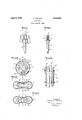
- Fig. 1 is a side elevation of a medicine dropper, partly cut away, incorporating my invention
- Fig. 2 is a side elevation of the dropper tube part of the medicine dropper of Fig. l, and illustrates one embodiment of my invention
- Fig. 3 is an enlarged view of Fig. 1, taken along lines 3 3, illustrating the respective positions of the bulb 2,329,682 Pa Qn edAPr-B, 5
- Fig. 4 illustrates the bulb of Fig. 3 being squeezed along line A-A;
- Fig. 5 illustrates the bulb, being. squeezed along line B-B;
- Fig. 6 illustrates another embodiment of my invention.
- amedicine dropper generally designated by reference numeral 1 consisting of a resilient bulb 2, a dropper tube 3 connected to the bulb to provide an airtight passageway between the interior of the bulb and the dropper tube bore 4, and a cap 5 which is adapted to attach the medicine dropper to a container.
- the skirt of cap 5. may be provided with threads on its interior for screw engagement with the neck of a container, in the well-known manner.
- dropper tube 3 The upper end of dropper tube 3 is provided with a flange 6 adapted to engage within cap 5 or with bulb 2 to connect theparts of the medicine dropper together.
- dropper tube 3 is.
- a plurality of elongated rod-like members or fingers 7 and 7 formed integrally with the dropper tube and sufficiently long to extend up wardly into the interior of resilient bulb 2 substantially to. its top inner surface.
- the four elongated members are. disposed evenly around bore 4 in the dropper tube to form two pairs of diametrically opposed members 7, 7 and '7', '7 which are integrally at tached to the dropper tube at their, lower ends.
- the members are joined by a thin, flexible web 8. adjacent their upper ends, for reasons to be described more fully below.
- Fig. 3 the respective positions of the. two diametrically opposed pairs ct members and the adjacent walls of the resilient bulb 2 are shown when the device is in position inside the resilient bulb.
- resilient bulb 2 is squeezed along a line of a pair of opposed members 7, 7, (line A A)
- opposed members 7, 7 are urged to wards each other until their respective inner surfaces 9, 9 contact each other, thereby preventing the resilient bulb from being squeezed.
- the other pair of diametri cally opposed members which, for purposes of convenience have been referred to as 7, 7, will be. urged outwardly, in the manner shown, due to their attachment by thin, flexible web 8 which joins all members together.
- the width a of each of the members is approximately one-half theirthickness b so that when a pair of diametrically opposed members contact each other, together they form substantially a square in the center of the bulb interior, as shown in Fig. 4, the length of the sides of which are approximately equal to the thickness 1).
- the. resilient bulb Walls can only be squeezed to the same point each time.
- members 7', 7' are urged outwardly, because they are joined by interconnecting web 3, and orient thernselves with their thickness b substantially in alignment with the direction of squeezing A ,A As shown in Fig.
- all four members form, in effect, a rectangular stop in the center of the interior of bulb 2 which limits the travel of the bulb walls to the same extent each time when the bulb is squeezed.
- the bulb walls will contact the sides of a member 7 instead of urging the pair of members 7, 7 into contact with each other and thus are prevented from being squeezed further. Formation of creases in the bulb walls will thereby be prevented, even though the bulb is squeezed on a line slightly oif line -A and h r e a he bulb e l i l be stopped a l a.
- d s n e rom the qua to nne ish is equal to twice the width 0 of the members.
- the members come into the operation in the manner shown in Fig. to limit the travel of the bulbwalls.
- inner surfaces 9, 9' respectively of members 7 and 7 adjacent each other will come into contact and the bulb walls will be separated by a distance equal to twice the width at, which is also equal to thickness 12. Therefore, regardless of the direction in which the bulb is squeezed, the members come into operation and act in unison to prevent the bulb walls from contacting each other.
- Fig. 6 there is shown another embodiment of the invention which is formed as a unit separate from the other parts of the dropper.
- members 10, whose dimensions are the same as noted above in connection with members '7 and 7, are connected by a flexible web 11 adjacent their upper ends and a similar web 12 adjacent their lower ends.
- the upper ends of the members may be tapered as shown to conform generally to the upper interior curved surface of a resilient bulb.
- the lower ends of the members are flat.
- the device is placed inside the resilient bulb part of a medicine dropper with lower ends of members resting on top of flange 6 on dropper tube 3.
- Members 10 are sufficiently long to extend upwardly into the interior of the bulb substantially to the top inner surface of the bulb.
- this embodiment may also be made from plastic, such as polyethylene, which has the desired flexibility.
- a dispenser comprising, in combination, a resilient bulb, a dropper tube, means for attaching said dispenser to a container, and devices positioned in the interior of said bulb to limit the travel of the bulb walls when said bulb is squeezed, said devices comprising a plurality of interconnected rod-like members.
- a dispenser comprising, in combination, a resilient bulb, a dropper tube, means for attaching said dispenser to a container, and devices positioned in the interior of said bulb to limit the travel of the bulb walls when said bulb is squeezed, said devices comprising a plurality of flexible interconnected rod-like members, the width of said members being approximately twice their thickness.
- a dispenser comprising, in combination, a resilient bulb, a dropper tube, means for attaching said dispenser to a container, said dropper tube having a plurality of flexible interconnected rod-like members extending a substantial distance into the interior of said bulb, said members limiting the travel of the bulb walls when said bulb is squeezed.
- a dispenser comprising, in combination, a resilient bulb, a dropper tube, means for attachingsaid dispenser to a container, said dropper tube having a plurality of flexible interconnected rod-like members extending a substantial distance into the interior of said bulb, the width of said members being approximately twice their thickness, said members limiting the travel of the bulb walls when said bulb is squeezed.
- a dispenser comprising, in combination, a resilient bulb, a dropper tube, means for attaching said dispenser to a container, said dropper tube having at least two pairs of diametrically opposed rod-like members at the upper part thereof, said members extending a substantial distance into the interior of said bulb, said members limiting the travel of the bulb walls when said bulb is squeezed.
- a dispenser comprising, in combination, a resilient bulb, a dropper tube, means for attaching said dispenser to a container, said dropper tube having at least two pairs of diametrically opposed rod-like members at the upper part thereof extending a substantial distance into the interior or" said bulb, said members being joined by a flexible web.
- a dispenser comprising, in combination, a resilient bulb, a dropper tube, means for attaching said dispenser to a container, said dropper tube having at least two pairs of diametrically opposed rod-like members at the upper part thereof extending a substantial distance into the interior of said bulb, said rod-like members being joined by a flexible web, the width of said rod-like mem bers being approximately twice their thickness.
- devices to be positioned within the bulb part of said dropper to limit the travel of the walls of said bulb part when said bulb part is squeezed, said devices comprising, a plurality of connected rod-like members disposed substantially in a circle, the width of said members being approximately twice their thickness.
- devices to be positioned within the bulb'p'artoi said dropper to limit the travel of the walls of said bulb part when said bulb part is squeezed comprising, a plurality of rod-like members disposed in substantially. dia-.
- devices to be positioned within the bulb part of said dropper to limit the travel of the walls of said bulb part when said bulb part is squeezed comprising, a plurality of rod-like members disposed in substantially diametrically opposed pairs, said members being joined adjacent their upper and lower ends by flexible webs.
- devices to be positioned within the bulb part of said dropper to limit the travel of the walls of said bulb part when said bulb part is squeezed comprising, at least two pairs of diametrically opposed rod-like members, the thickness of said members being approximately twice their width, adjacent rod-like members being joined to each other by a flexible web.
- a dispenser comprising, in combination, a resilient bulb, a dropper tube, means for attaching said dispenser to a container, said dropper tube having a plurality of integrally attached rod-like members extending a substan tial distance into the interior of said bulb, said members being interconnected by a flexible web, said members limiting the travel of the bulb walls when said bulb is squeezed.
Landscapes
- Health & Medical Sciences (AREA)
- Clinical Laboratory Science (AREA)
- Chemical & Material Sciences (AREA)
- Chemical Kinetics & Catalysis (AREA)
- Medical Preparation Storing Or Oral Administration Devices (AREA)
Description
April 8, 1958 c. CASTELLI DISPENSER Filed July 27, 1955 INVENTOR '55 6417544 TTORNEY nite States DISPENSER Charles Castelli, New Brunswick, N. J assignor to Johnson & Johnson, a corporation of lew jersey Application July 27, 1955, SerialNo, 524,675
12 Claims. (Cl; 141-44)- This invention relates to dispensers of the medicine dropper type and more particularly to extending the life of the resilient bulb part of such dispensers.
Liquid o r semi-liquid dispensers of the medicine dropper type generally include a resilient bulb, a dropper tube and a cap or plug for securing the dispenser to a container. These dispensers usually have a dropper tubernade of glass, a cap or plug of bakelite, and a resilient bulb of rubber. Rubber is particularly suitable for the bulb part of the dispenser because it possesses the desired resiliency and flexibility.
Although these materials are still used extensively in the manufacture of such dispensers, it is becoming more common to make the dispenser parts from plastics, such as polyethylene, because plastics are readily available at low cost and may be molded in various forms and attractive colors. In addition, some plastics can Withstand sterilization procedures which often impair the resiliency and elasticity of rubber and thus the effectiveness of the resilient bulb.
Although more dispensers of this type are being made from plastics, these materials possess certain disadvantages. This is particularly true of resilient bulbs made of plastics in that they often have been found to lack the flex life of resilient bulbs made of rubber.
During the normal use of this type dispenser, the resilient bulb part is squeezed or flexed a considerable number of times. The bulb is usually squeezed until opposed inner surfaces of the bulb walls contact or nearly contact each other. This results in the formation of creases in the bulb walls, and, particularly when plastics are used, ultimately in the formation of cracks, thus causing bulb failure and making the dispenser useless. Apparently, this failure is brought about by crystallization, or some similar phenomenon, which causes fatigue in the bulb material,
I have discovered that the flex life of the resilient bulb part of such dispensers may be extended by limiting the travel of the bulb walls the bulb is squeezed to prevent formation of the creases which ultimately cause failure. In accordance with my invention, the travel of the bulb walls may be so limited by providing devices positioned in the interior of the resilient bulb These devices may be a separate member or may be integrally formed with another part of the dispenser.
To more fully understand the nature of my invention, reference; is made to, the accompanying drawing wherein there are shown various illustrative embodiments of my invention and wherein like numerals refer to like parts.
In the drawings:
Fig. 1 is a side elevation of a medicine dropper, partly cut away, incorporating my invention;
Fig. 2 is a side elevation of the dropper tube part of the medicine dropper of Fig. l, and illustrates one embodiment of my invention;
Fig. 3 is an enlarged view of Fig. 1, taken along lines 3 3, illustrating the respective positions of the bulb 2,329,682 Pa Qn edAPr-B, 5
2 walls and devices positioned in the. interior of the bulb to limit the travel of the bulb walls;
Fig. 4 illustrates the bulb of Fig. 3 being squeezed along line A-A;
Fig. 5 illustrates the bulb, being. squeezed along line B-B; and
Fig. 6 illustrates another embodiment of my invention.
In the drawings, there is shown amedicine dropper generally designated by reference numeral 1 consisting of a resilient bulb 2, a dropper tube 3 connected to the bulb to provide an airtight passageway between the interior of the bulb and the dropper tube bore 4, and a cap 5 which is adapted to attach the medicine dropper to a container. The skirt of cap 5. may be provided with threads on its interior for screw engagement with the neck of a container, in the well-known manner.
The upper end of dropper tube 3 is provided with a flange 6 adapted to engage within cap 5 or with bulb 2 to connect theparts of the medicine dropper together.
In this embodiment of the invention, dropper tube 3 is.
provided above flange 6 with a plurality of elongated rod-like members or fingers 7 and 7 formed integrally with the dropper tube and sufficiently long to extend up wardly into the interior of resilient bulb 2 substantially to. its top inner surface. As shown in Figs. 2 and 3, the four elongated members are. disposed evenly around bore 4 in the dropper tube to form two pairs of diametrically opposed members 7, 7 and '7', '7 which are integrally at tached to the dropper tube at their, lower ends. The members are joined by a thin, flexible web 8. adjacent their upper ends, for reasons to be described more fully below.
In Fig. 3, the respective positions of the. two diametrically opposed pairs ct members and the adjacent walls of the resilient bulb 2 are shown when the device is in position inside the resilient bulb. When resilient bulb 2 is squeezed along a line of a pair of opposed members 7, 7, (line A A), opposed members 7, 7 are urged to wards each other until their respective inner surfaces 9, 9 contact each other, thereby preventing the resilient bulb from being squeezed. further. The other pair of diametri cally opposed members which, for purposes of convenience have been referred to as 7, 7, will be. urged outwardly, in the manner shown, due to their attachment by thin, flexible web 8 which joins all members together. In the preferred form, of the invention, the width a of each of the members is approximately one-half theirthickness b so that when a pair of diametrically opposed members contact each other, together they form substantially a square in the center of the bulb interior, as shown in Fig. 4, the length of the sides of which are approximately equal to the thickness 1). In this manner, the. resilient bulb Walls can only be squeezed to the same point each time. Simultaneously, when bulb 2 is squeezed along line A-A, members 7', 7' are urged outwardly, because they are joined by interconnecting web 3, and orient thernselves with their thickness b substantially in alignment with the direction of squeezing A ,A As shown in Fig. 4, all four members form, in effect, a rectangular stop in the center of the interior of bulb 2 which limits the travel of the bulb walls to the same extent each time when the bulb is squeezed. if the bulb is squeezed slightly to the side of line AA, the bulb walls will contact the sides of a member 7 instead of urging the pair of members 7, 7 into contact with each other and thus are prevented from being squeezed further. Formation of creases in the bulb walls will thereby be prevented, even though the bulb is squeezed on a line slightly oif line -A and h r e a he bulb e l i l be stopped a l a. d s n e rom the qua to nne ish is equal to twice the width 0 of the members.
If the bulb is squeezed along a line between the line defined by a pair of diametrically opposed members, for example, along line BB, the members come into the operation in the manner shown in Fig. to limit the travel of the bulbwalls. In this event, inner surfaces 9, 9' respectively of members 7 and 7 adjacent each other will come into contact and the bulb walls will be separated by a distance equal to twice the width at, which is also equal to thickness 12. Therefore, regardless of the direction in which the bulb is squeezed, the members come into operation and act in unison to prevent the bulb walls from contacting each other. It is thus seen that when the bulb is squeezed in the normal manner, the travel of the bulb walls'is always stopped at the same point and the bulb walls separated at a distance from each other approximately equal to the thickness bjof the members, regardless of the direction in which the bulb is squeezed. As shown in Figs. 4 and 5, when the bulb is squeezed, the bulb walls assume a rounded, even curvature and the sharp creases which cause failure are eliminated.
In Fig. 6, there is shown another embodiment of the invention which is formed as a unit separate from the other parts of the dropper. In this embodiment, members 10, whose dimensions are the same as noted above in connection with members '7 and 7, are connected by a flexible web 11 adjacent their upper ends and a similar web 12 adjacent their lower ends. The upper ends of the members may be tapered as shown to conform generally to the upper interior curved surface of a resilient bulb. The lower ends of the members are flat. In this embodiment, the device is placed inside the resilient bulb part of a medicine dropper with lower ends of members resting on top of flange 6 on dropper tube 3. Members 10 are sufficiently long to extend upwardly into the interior of the bulb substantially to the top inner surface of the bulb. As noted above, this embodiment may also be made from plastic, such as polyethylene, which has the desired flexibility.
From the foregoing illustrative embodiments, it is apparent that, by means of my invention, the formation of sharp creases in bulb walls and consequent bulb failure will be prevented, and the flex life of the bulb extended by limiting the travel of the bulb walls, regardless of the direction in which the bulb is squeezed in the customary manner. While the device of this invention is particularly suitable in extending the flex life of resilient bulbs made of plastic, it is equally suitable for the same purpose in the case of bulbs made of other materials, including rubber. It is also apparent that, although two pairs of diametrically opposed members have been shown in the illustrative embodiments, more or less may be used and that other variations, modifications and substitutions may be made without departing from the spirit of the invention.
The claims are:
1. A dispenser comprising, in combination, a resilient bulb, a dropper tube, means for attaching said dispenser to a container, and devices positioned in the interior of said bulb to limit the travel of the bulb walls when said bulb is squeezed, said devices comprising a plurality of interconnected rod-like members.
2. A dispenser comprising, in combination, a resilient bulb, a dropper tube, means for attaching said dispenser to a container, and devices positioned in the interior of said bulb to limit the travel of the bulb walls when said bulb is squeezed, said devices comprising a plurality of flexible interconnected rod-like members, the width of said members being approximately twice their thickness.
3. A dispenser comprising, in combination, a resilient bulb, a dropper tube, means for attaching said dispenser to a container, said dropper tube having a plurality of flexible interconnected rod-like members extending a substantial distance into the interior of said bulb, said members limiting the travel of the bulb walls when said bulb is squeezed.
4. A dispenser comprising, in combination, a resilient bulb, a dropper tube, means for attachingsaid dispenser to a container, said dropper tube having a plurality of flexible interconnected rod-like members extending a substantial distance into the interior of said bulb, the width of said members being approximately twice their thickness, said members limiting the travel of the bulb walls when said bulb is squeezed.
5. A dispenser comprising, in combination, a resilient bulb, a dropper tube, means for attaching said dispenser to a container, said dropper tube having at least two pairs of diametrically opposed rod-like members at the upper part thereof, said members extending a substantial distance into the interior of said bulb, said members limiting the travel of the bulb walls when said bulb is squeezed.
6. A dispenser comprising, in combination, a resilient bulb, a dropper tube, means for attaching said dispenser to a container, said dropper tube having at least two pairs of diametrically opposed rod-like members at the upper part thereof extending a substantial distance into the interior or" said bulb, said members being joined by a flexible web.
7. A dispenser comprising, in combination, a resilient bulb, a dropper tube, means for attaching said dispenser to a container, said dropper tube having at least two pairs of diametrically opposed rod-like members at the upper part thereof extending a substantial distance into the interior of said bulb, said rod-like members being joined by a flexible web, the width of said rod-like mem bers being approximately twice their thickness.
8. For use with a dispenser of the medicine dropper type, devices to be positioned within the bulb part of said dropper to limit the travel of the walls of said bulb part when said bulb part is squeezed, said devices comprising, a plurality of connected rod-like members disposed substantially in a circle, the width of said members being approximately twice their thickness.
9. For use with a dispenser of the medicine dropper type, devices to be positioned within the bulb'p'artoi said dropper to limit the travel of the walls of said bulb part when said bulb part is squeezed comprising, a plurality of rod-like members disposed in substantially. dia-.
metrically opposed pairs, said members being joined by a flexible web.
10. For use with a dispenser of the medicine dropper type, devices to be positioned within the bulb part of said dropper to limit the travel of the walls of said bulb part when said bulb part is squeezed comprising, a plurality of rod-like members disposed in substantially diametrically opposed pairs, said members being joined adjacent their upper and lower ends by flexible webs.
11. For use with a dispenser of the medicine dropper type, devices to be positioned within the bulb part of said dropper to limit the travel of the walls of said bulb part when said bulb part is squeezed comprising, at least two pairs of diametrically opposed rod-like members, the thickness of said members being approximately twice their width, adjacent rod-like members being joined to each other by a flexible web.
12. A dispenser comprising, in combination, a resilient bulb, a dropper tube, means for attaching said dispenser to a container, said dropper tube having a plurality of integrally attached rod-like members extending a substan tial distance into the interior of said bulb, said members being interconnected by a flexible web, said members limiting the travel of the bulb walls when said bulb is squeezed.
References Cited in the file of this patent UNITED STATES PATENTS
Priority Applications (1)
| Application Number | Priority Date | Filing Date | Title |
|---|---|---|---|
| US524675A US2829682A (en) | 1955-07-27 | 1955-07-27 | Dispenser |
Applications Claiming Priority (1)
| Application Number | Priority Date | Filing Date | Title |
|---|---|---|---|
| US524675A US2829682A (en) | 1955-07-27 | 1955-07-27 | Dispenser |
Publications (1)
| Publication Number | Publication Date |
|---|---|
| US2829682A true US2829682A (en) | 1958-04-08 |
Family
ID=24090219
Family Applications (1)
| Application Number | Title | Priority Date | Filing Date |
|---|---|---|---|
| US524675A Expired - Lifetime US2829682A (en) | 1955-07-27 | 1955-07-27 | Dispenser |
Country Status (1)
| Country | Link |
|---|---|
| US (1) | US2829682A (en) |
Citations (2)
| Publication number | Priority date | Publication date | Assignee | Title |
|---|---|---|---|---|
| US694530A (en) * | 1899-05-25 | 1902-03-04 | Harris Comer | Pipette. |
| US2311367A (en) * | 1940-04-22 | 1943-02-16 | Laura A Chambers | Liquid applicator |
-
1955
- 1955-07-27 US US524675A patent/US2829682A/en not_active Expired - Lifetime
Patent Citations (2)
| Publication number | Priority date | Publication date | Assignee | Title |
|---|---|---|---|---|
| US694530A (en) * | 1899-05-25 | 1902-03-04 | Harris Comer | Pipette. |
| US2311367A (en) * | 1940-04-22 | 1943-02-16 | Laura A Chambers | Liquid applicator |
Similar Documents
| Publication | Publication Date | Title |
|---|---|---|
| US4133457A (en) | Squeeze bottle with valve septum | |
| US4109836A (en) | Self-sealing paste dispensing device | |
| US4029202A (en) | Container with plastic cap and display rack therefore | |
| US5848993A (en) | Bulb syringe providing for visual observation of contents thereof and for enhanced deflation/inflation control | |
| US2644663A (en) | One-piece check valve of molded resilient material | |
| US2549404A (en) | Bottle stopper | |
| US4180938A (en) | Bubble blowing wand | |
| US3491757A (en) | Hypodermic syringe with non-turning tip connector | |
| US3346187A (en) | Flexible drinking straws | |
| US1607993A (en) | Container tube | |
| KR920016079A (en) | Tips for Fluid Dosers with Concave Dosing Nozzles | |
| ES2386343T3 (en) | Reduced piece that forms an instillation vessel | |
| US2812764A (en) | Nursing bottle and nipple construction | |
| US3650271A (en) | Nipple for baby bottle | |
| US1961490A (en) | Syringe equipment | |
| US2207176A (en) | Fluid can with resilient spout | |
| US1531245A (en) | Dispensing nipple | |
| US4045070A (en) | Container handle | |
| US2197672A (en) | Delivery closure for collapsible containers | |
| BR112015010826A2 (en) | multi-flow metering stopper and olive oil | |
| US2829682A (en) | Dispenser | |
| US3495745A (en) | Sealing structures | |
| US2423356A (en) | Pessary | |
| US3190511A (en) | Plastic bottle pourer | |
| CH348779A (en) | Container closure |