US2829342A - Time measuring system - Google Patents
Time measuring system Download PDFInfo
- Publication number
- US2829342A US2829342A US468075A US46807554A US2829342A US 2829342 A US2829342 A US 2829342A US 468075 A US468075 A US 468075A US 46807554 A US46807554 A US 46807554A US 2829342 A US2829342 A US 2829342A
- Authority
- US
- United States
- Prior art keywords
- counter
- pulses
- pulse
- frequency
- gate
- Prior art date
- Legal status (The legal status is an assumption and is not a legal conclusion. Google has not performed a legal analysis and makes no representation as to the accuracy of the status listed.)
- Expired - Lifetime
Links
- 210000002105 tongue Anatomy 0.000 description 30
- 230000000306 recurrent effect Effects 0.000 description 14
- 230000000694 effects Effects 0.000 description 11
- 238000010586 diagram Methods 0.000 description 10
- 230000007246 mechanism Effects 0.000 description 9
- 238000004804 winding Methods 0.000 description 9
- 238000005259 measurement Methods 0.000 description 6
- 238000000034 method Methods 0.000 description 4
- 238000001228 spectrum Methods 0.000 description 4
- 238000012935 Averaging Methods 0.000 description 3
- 230000009471 action Effects 0.000 description 3
- 230000008859 change Effects 0.000 description 3
- 230000007935 neutral effect Effects 0.000 description 3
- 230000004044 response Effects 0.000 description 3
- 239000000969 carrier Substances 0.000 description 2
- 238000013461 design Methods 0.000 description 2
- 238000010304 firing Methods 0.000 description 2
- 239000010445 mica Substances 0.000 description 2
- 229910052618 mica group Inorganic materials 0.000 description 2
- 238000007493 shaping process Methods 0.000 description 2
- 238000012360 testing method Methods 0.000 description 2
- DXMQZKIEVHKNTN-UHFFFAOYSA-N 2-[carbamimidoyl(ethyl)amino]acetic acid Chemical compound CCN(C(N)=N)CC(O)=O DXMQZKIEVHKNTN-UHFFFAOYSA-N 0.000 description 1
- QPLDLSVMHZLSFG-UHFFFAOYSA-N Copper oxide Chemical compound [Cu]=O QPLDLSVMHZLSFG-UHFFFAOYSA-N 0.000 description 1
- 239000005751 Copper oxide Substances 0.000 description 1
- 240000008042 Zea mays Species 0.000 description 1
- 235000005824 Zea mays ssp. parviglumis Nutrition 0.000 description 1
- 235000002017 Zea mays subsp mays Nutrition 0.000 description 1
- 230000003321 amplification Effects 0.000 description 1
- 238000013459 approach Methods 0.000 description 1
- 230000005540 biological transmission Effects 0.000 description 1
- 229910000431 copper oxide Inorganic materials 0.000 description 1
- 235000005822 corn Nutrition 0.000 description 1
- OYFJQPXVCSSHAI-QFPUQLAESA-N enalapril maleate Chemical compound OC(=O)\C=C/C(O)=O.C([C@@H](C(=O)OCC)N[C@@H](C)C(=O)N1[C@@H](CCC1)C(O)=O)CC1=CC=CC=C1 OYFJQPXVCSSHAI-QFPUQLAESA-N 0.000 description 1
- 230000003628 erosive effect Effects 0.000 description 1
- 238000007429 general method Methods 0.000 description 1
- 238000003780 insertion Methods 0.000 description 1
- 230000037431 insertion Effects 0.000 description 1
- 230000002452 interceptive effect Effects 0.000 description 1
- 238000003199 nucleic acid amplification method Methods 0.000 description 1
- 230000010355 oscillation Effects 0.000 description 1
- 238000003825 pressing Methods 0.000 description 1
- 230000008569 process Effects 0.000 description 1
- 238000010791 quenching Methods 0.000 description 1
- 230000009467 reduction Effects 0.000 description 1
- 238000004353 relayed correlation spectroscopy Methods 0.000 description 1
- 238000004904 shortening Methods 0.000 description 1
- 230000011664 signaling Effects 0.000 description 1
- 230000001052 transient effect Effects 0.000 description 1
- 230000007704 transition Effects 0.000 description 1
Images


Classifications
-
- G—PHYSICS
- G04—HOROLOGY
- G04F—TIME-INTERVAL MEASURING
- G04F10/00—Apparatus for measuring unknown time intervals by electric means
- G04F10/04—Apparatus for measuring unknown time intervals by electric means by counting pulses or half-cycles of an AC
Definitions
- Patent No. 2,'7tltl,l33 dated ⁇ lanuary 1S, 1955. Divided and this application November 1t), i954, Serial No. 468,075
- This invention relates to time measuring systems with particular emphasis upon improving the accuracy of such a system in the presence of noise currents which tend to interfere with the application of electrical counting methods to the measurement of time intervals.
- An object of the invention is to sum up electrical counts during a succession of recurrent substantially equal time intervals to obtain an average value for a single such interval.
- a feature of the invention is a control system for counting the individual time intervals as well as the total number of cycles of a standard wave source occurring during the intervals and for automatically stopping both counts when a desired number of intervals have occurred.
- Another feature is a noise indicator useful in determining how many intervals should be counted in order that the average time per interval may be determined with a desired degree of accuracy.
- Fig. l is a single-line schematic diagram of an illustrative system embodying the invention.
- Fig. 2 is a single-line schematic diagram of an illustrative sending device
- FIG. 3 is a group of illustrative oscillograms of currents in various circuit branches of the system of Fig. 2;
- Fig. 4 is a single-line schematic diagram of an illustrative receiving device
- Figs. 5 and 6 taken together provide a double-line schematic diagram of an illustrative receiver in greater detail than shown in Fig. 4;
- Fig. 7 is a group of illustrative oscillograms of currents in various circuit branches of the systems of Figs. 4, 5, and 6;
- Fig. 8 is a group of enlarged oscillograms of currents in certain circuit branches in the systems of Figs. 4, 5, and 6;
- Fig. 9 is a schematic diagram of a noise indicator
- Fig. l() is a tabulation of a sequence of relay operations involved in the operation of the noise indicator of Fig. 9;
- Fig. ll is a schematic diagram of an alternative Vgating system for use at a sending terminal
- Fig. l2 is a schematic diagram of a gate control circuit employing a pentagrid vacuum tube
- Fig. i3 is a schematic diagram of a portieri of an alternative receiving arrangement.
- a method of measuring envelope delay distortion as applied over a straightaway circuit or line which comprises (a) sending periodically onto the line to be measured a pulse of reference frequency tone and a pulse of comparison or measuring frequency tone, one after the other, preferably with restricted sidebands,
- @rates Patentice (b) counting the time eiapsingbetween arrivals of particular amplitudes of these pulses envelopes at the receiving end, and (c) averaging the results of a multiplicity of such counts when it is desired to reduce fortuitous effects such as caused by noise.
- the averaged count may be automatically indicated; and successive indications, each taken with a different measuring frequency and using the same time interval between sent tones, give substantially the envelope delay distortion vs. frequency characteristic except for a constant delay which is usually unimportant. lf the absolute delay is desired, it can be obtained when measuring is doneon a loop rather than on a straightaway basis.
- the sidebands of the reference frequency signal need not be restricted to such a narrow band as 50 cycles, because it is not necessary that its delay approximate dpr/dw. Any delay value is satisfactory for vthe reference pulse so long as it is constant. However, the greater the restriction of bandwidth, the easier it becomes to use measuring frequencies close to the reference frequency without erroneous operation of selective receiving circuits due to overlapping of frequency spectra of these tones. By using wide sidebands forthe reference tone and by giving it a steep wave front the need for much ampiiiication of the reference wave at the receiving end diminishes, as discussed below.
- the frequency spectrum of the reference tone should not contain much energy in the frequency range used for the measuring' tone, and consequently it is then diicult to measure delay distortion very close to the reference frequency.
- the use of two reference frequencies iS then generally necessary in order to obtain a complete delay distortion characteristic over all parts of the desired frequency range.
- the illustrative examples disclosed hereinafter do not use wide sidebands, this possibility is available in case one wishes to trade cost and weight of apparatus for the slight inconvenience of using two reference frequencies.
- measuring preferably is done between peak values ⁇ of the detected envelope Waves assassin of these tones because small amounts of level variation or selective attenuation on the line do not appreciably affect the mechanisms ability to discern the instants of maximum current.
- the transitions in the differentiators output wave may be greatly amplified, as is accomplished partly by nonlinear coils which generate a sharp impulse of high voltage, and partly by linear amplification.
- an electronic counter measures delay precisely in one observation, the value may be influenced by interfering effects such as caused by noise. Therefore it is generally advantageous to design the counter so that it makes a number of delay measurements and indicates the average value.
- Fig. 1 is a simplified schematic diagram of an illustrative system having the basic elements required in the practice of the invention.
- Sinusoidally-enveloped pulses of a suitable high frequency carrier are produced at accurately timed intervals at the sending end of the transducer 1 to be measured, such as a line by means of a pulse repetition frequency source 2 of frequency such as 25 cycles reacting with a carrier oscillator 3, of frequency such as 97,000 cycles, in a first modulator d.
- the resulting modulated wave is impressed upon a second modulator 5 along with selected and timed pulses of standard and variable comparison frequency oscillations of uniform duration from oscillators 6 and 7 respectively.
- the pulses of standard frequency are under the control of a first gate 8 and those of the variable frequency under the control of a second gate 9, both gates being operated by a gate control device 10 which in turn is under the control of the low frequency source 2.
- the device i0 upon being manually started by the operator, first opens gate 8 to pass one pulse of standard frequency, then closes gate 8 for a selected number of pulse intervals, generally only one pulse interval, as in the illustrative system, then opens gate 9 and passes one pulse of comparison frequency,
- the modulator 5 shifts the standard and variable comparison pulses downward in frequency to the desired values of frequency with which the transducer 1 is to be tested, for example, the standard pulses may be shifted to 3000 cycles and the variable frequency pulses to the range 20() to 20,000 cycles, a low pass filter 34 being inserted between the modulator 5 and the transducer 1.
- a band filter 11 selects the 3000 cycle pulse which is thereupon translated into a sharp impulse by means of a detector 12, a ditferentiator 13 and an impulse generator 14.
- the common frequency may advantageously be placed at 97,000
- the 97,000 cycle resulting pulse is translated into a sharp impulse by means of a detector 17, a ditferentiator 18 and an impulse generator 19.
- the first impulse upon the generator 14 is used to actuate a start-stop mechanism 20 which in turn actuates a gate device 21 which connects a standard counting cycle generator 22 to a cycle counter 23 which counts cycles from the generator 22 as long as the gate 21 remains open.
- the next impulse which cornes from gen erator 19, shuts off the counting cycle generator, and, registers a count of one on a sample counter 24.
- the sample counter 24 stops the counting process by actuating the start-stop mechanism 20 to close the gate 21.
- the total count is shown on the count indicator 25, and is an automatically averaged value of all sample counts, as explained more fully hereinafter.
- Sending apparatus The purpose of the sender is to transmit to the sending end of the line under test successive modulated spurts of reference and variable comparison frequency separated by xecl time intervals of zero current as shown by the oscillogram of current I7 in Fig. 3.
- the reference frequency as illustrated is (97 lie-fa) where fa may have any convenient number of fixed values, and the variable frequency is (97 lio-fb) in the example shown.
- These two voice frequencies are the result of heterodyning in the example hereinafter described.
- the envelope wave of these spurts is substantially sinusoidal as explained below, and resembles a 25 cycle wave in the system.
- the duration of each spurt is .04 second when the modulating wave is 25 cycles.
- the time elapsing between the peak value of the reference tone and the peak value of the next following spurt of variable frequency tone is assumed to be fixed, at .08 second. Therefore there is zero output during .04 second of this interval.
- This interval may be made greater if desired depending upon whether the envelope delay in the line is appreciably greater at the reference frequency than at any variable frequency used, it being necessary that these pulses shall not overlap at the receiving end of the line.
- the choice of the time elapsing between the peak value of the variable frequency tone and the peak of the next succeeding reference frequency spurt depends upon the amount of delay distortion to be measured, since it is necessary that the spurt of variable freq ency tone shall not overlap or run into the spurt of reference frequency tone at the receiving end of the line. it is evident that the duration of the zero current interval following a pulse of variable frequency at the sender output should about equal the mMimum value of delay distortion to be measured.
- FIG. 3 Illustrative sports or pulses are shown in Fig. 3 as current I7 and in order to obtain current l?, the sending device may be shown schematically by thc single-line diagram in the upper portion of Fig. 2.
- a source 216 of accurate frequency provides the input wave of a multivibrator or frequency divider 27 whose output is the first modulating frequency, for example, 25 cycles per second in the case of certain telephotograph circuits.
- the 25 cycle wave passes over a hybrid coil 30 and one output thereof is connected to one input of the first modulator 4.
- the other input of this rnoduiator an accurate high frequency, for example 97 kilocycles obtained either as a harmonic of the accurate source 26 through the connection 29 as shown (or from the freqic v divider 27).
- the value 97 kilocycles is assumed for rustratirc purposes.
- a narrow bandpass filter 31 is shown at the output of thc first modulator sidebands passed by this filter are narrow so that the current I3 at its output has only three frequencies: 96.975, 97.0, and 97.025 kilocycles.
- the amplitudes of cycics per second and 97 kilocycles applied to modulator' 4 preferably are adjusted so that I3 is 100 percent modulated as shown in the oscillogram of Fig. 3. If the control source Zu is a 50 cycle pcrpsecond tuning fork the connection 29 may be used,
- the narrow bandpass filter b of approximately 50 cycle width is used in the signal shifter to reduce the line noise and other disturbances if present.
- the bandpass filters 22 and for two reference frequencies are also of about 50 cycle width when the sent pulses of reference frequency are thus restricted in frequency spectrum as this favors measuring fairly close to the reference frequency without appreciable error.
- the low pass filters and 54- immediately following the respective de.ectors l2 and i7 consist of series resistors and shunt condensers because inductances at high levels are apt to be nonlinear and to cause varying effects as the level changes slightly. These filters suppress the carriers. No wave shaping is required of these filters due to the wave shaping action of t ie sending bandpass filters.
- Coils L21 ⁇ and L22 are nonlinear and operate to produce sharp wave fronts in currents T51 and g so that the voltages across resistors R21 and rise from O to 8 volts in about two microseconds. The optimum values for circuit elements connecting to these nonlinear coils may be found by trial.
- Iuductances L11 and L12 help to suppress the carriers and prevent discharge of condensers C21 and C22 toward the source. These inductances should be substantially linear. Each may consist of one or more retard coils. The inductance of such coils should be determined experimentally to obtain the desired maximum amplitudes for 111, and i12 with a minimum of input power and without excessive transients. Initial fluctuations during the build up of T or i12 are not wanted as they may cause unwanted pulses in lm and T52 ahead of the desired times which might give false operation of gas tubes.
- a Zero reset switch S11 is provided and when this has been closed momentarii gas tube G. il is not firing and a neutral relay Nlr is released so that a pulse of 1 11 is transmitted over the contact of NR4 and resistor 1-21 to the grid of gas tube G. T. 2l which res to open the vacuum tube gate 3S.
- the next succeeding pulse in im is transmitted over resistor i'31 to the grid of gas tube G. T. 3l which tires to close the gate. Accordingly the mesacycle current 113 which passes the gate has the duration T1. This is equal to the time interval elapsing between the sharp rises of the respective pulses in T51 and T52 provided currents 21 and :'31 articulate abruptiy with equal slopes to full value when the respective gas tubes fire.
- a relay 5R31 is necessary in series with the plate of gas tube G. T. 3T. which operates to cut off its plate voltage from source E11 and extiuguishcs both gus tubes very soon after gate closure.
- a relay Slim having substantially identical winding impedance to that of 8R31, is provided in the plate circuit of gas tube G. T. so that both plate circuits have substantially identical transient responses.
- the windings of 8R21 and 5R31 may be shunted by small condensers so as to obtain the nearest approach to rectangular on and off switching of the gate.
- the contacts of relay 8R21 are open at the tiring instant of gas tube G. to make sure that tube G. T. 2l tires before tube G. T. 3i., but close shortly thereafter to permit .ring of tube G. T. 3l on the next pulse of T52.
- the megacycle pulses in T13 are shown again to an enlarged scale in Fig. 8. They may be passed through a wave Shaper 65 to produce negative pulses of the same fundamental periodicity, as shown in the oscillogram of 114.
- the Shaper may be made of either tube circuits or varistor circuits, or a copper oxide varistor with a direct-current bias may be used to pass short pulses of only one polarity.
- the counting mechanism keeps adding up the number of megacycle pulses it receives not only during time interval T1 but also during T2 and succeeding time intervals measured until a predetermined number of such intervals have passed whereupon a pulse is received by the grid of a gas tube G. T. lll from an auxiliary series of binary counters, B. C. 11, B. C. 12, et cetera, which count the number of positive spikes in 151.
- This pulse fires the gas tube G. T. 11 and its plate current operates the relay NR1 to stop further spikes in 151 from acting on the counters, at which time the counter indication becomes stationary and may be read and recorded by the operator.
- NR4 Operation of NR4 should not occur until at least .04 (N -l) second has elapsed following the iinal spike in T51, and must be complete before .04N second has elapsed, in order to allow the gate to remain open for the longest necessary value of T and to make sure it does not open after the last value of T.
- N is the number of reference frequency spurt intervals between the envelope peaks of successive reference frequency spurts. Therefore, relay NR4 should be slow acting and its slowness should be adjustable if N is varied.
- the restoring of all counter circuits to the zero condition is accomplished by pressing the reset key S11 which operates reset relays 66 to make suitable voltage changes in the power supply of the counter stages, as discussed below.
- the circuits of relays NR11, NR21, and NR31 are provided for the purpose of driving a noise indicator as described below.
- This indicator detects variations in engths of successive spurts of the current 113. When these variations are excessive, the number of samples of the time intervals T1, T2, T3, et cetera, averaged by the megacycle counter should be increased as described more fully below.
- the number of sample averaged is controlled by a set of switches S32, S64, S1211, and S255. When all these switches are closed to the left, 512 samples are averaged. When one of these switches is closed to the right and the others are closed to the left, the number of samples averaged is the same as the subscript on the designation of the switch which is closed to the right.
- the time which is required for the counter to average a given number of samples is about equal to that number multiplied by .04N second.
- a wave Shaper 67 is also shown for inverting pulses T51 to produce the current pulses 115 used to drive the auxiliary counter. Pulses in 151 when inverted may be suitable for driving this counter. Therefore, the wave shaper 67 may be nothing but an inverter, for the purpose of changing positive pulses into negative pulses similar to 114.
- bandpass filters 62 and 63 should be just wide enough to pass them. A tenfold increase in these sidebands permits the received reference signal to build up about ten times as fast and changes the shape of I9 from sinusoidal to nearly rectangular.
- the differentiated current then consists of positive and negative spikes. By making use of one or the other of these spikes to fire G. T. 21 and to operate the auxiliary counter, one can omit L11, L21 and condenser C21 and probably decrease the size of amplifier 59 and detector l2.
- the values for R21 and for the low pass filter 4S would be changed, the resistors being much smaller as they need not dissipate as much heat.
- Counting mechanism It is assumed in the system illustrated that during a time interval T ranging in duration from about 40,000 to 40,000 (N l) microseconds, a precisely one megacycle current flows from the oscillator 22, Fig. l, suitable for operating an electronic pulse counter. The time interval and the one megacycle current iiow are repeated periodically, each such interval being separated by a short time of zero current. Due to small amounts of line noise not under control, slight ortuitous variations exist in the value T from one repetition to the next. In order to reduce the effect of these, and to obtain a better value of T, it is desirable to add and average a number of separate measurements of T. in accordance with the invention, apparatus is provided to automatically indicate the result in microseconds.
- the megacycle pulses of 11.2 in Figs. 5 and 6 are made to operate first on a binary electronic counter comprising n pairs of (or n double) tubes.
- the output of the binary counter is connected to a six stage decimal counter.
- the latter counter registers a digit about once in each 2n microseconds.
- the iinal reading of the decimal counter is the desired average value of T.
- Averaging of a plurality of measurements of T is eiected automatically by adjustment of a scale factor associated with the counting mechanism.
- An average being by deiinition the sum of m readings divided by n1 and the sum is equal to m times the average. For example, if the sum of eight readings is 1,600,000, the average is 200,000. Hence, if the counter counts once fory every eight cycles of the megacycle current, the result of impressing l,600,000 cycles upon the counter is an indicated count of 200,000 which gives the average directly eX- pressed.
- the counter may be arranged to count once for every 32 cycles, giving an indicated count of 200,000, thus once more directly indicating the average.
- the average value as indicated is independent of the number of samples averaged.
- the unit used in expressing the noise level is adjusted decibels, abbreviated dba, and refers to the reading olf a noise measuring set such as the Western Electric Companys No. 2 type described in Bell Laboratories Record, March 1936, volume i4, page 233, when used with an appropriate equalizer designed to weight the disturbing effect of noise currents of different frequencies and durations upon a telephotograph circuit, the noise measurement being made at the Zero level point of the line.
- the binary counter needs to have 9 double tubes or stages such as B. C. 2l to B. C. 29 in Figs. 5 and 6, so that n may be varied by desired amounts between 5 and 9, yusing switches S32, S64, S128, and S256 as described above.
- Noise indicator Noise on the line may reduce the accuracy of the timing of an interval by distorting, lengthening, or shortening of the pulses of T2 of Fig. 7, which in turn affects the shape of the detected pulses i9 and T11, and displacesfthe zero points of i12 and i12, and hence atects the spacing between the impulses T51 and i511.
- the net result is that either too many or too few cycles of the standard frequency are included in the intervals T1, T2, et cetera, of 112.
- the accuracy in the presence of line noise may be improved by including a large number of intervals in the cycle count. The more the effect of line noise, the more intervals should be included. As the eiect of line noise is random, it is very likely to make itself evident by making adjacent intervals unequal. The more noise, the more inequality is likely to be found.
- Fig. 5 it is shown that the output of. the vacuum tube gate 38 is tapped by a branch circuit delivering megacycle power to the noise indicator 58 shown simpiy by a box in this figure but shown more in detail in Fig. 9.
- leads 63 and a step-up transformer 69 impress a high megacycle voltage upon a rectifier 70 which may charge either condenser C71 or C72 over a high resistance R71. Therefore the charge on either condenser is proportional substantially to the charging time which is the same as the duration of a spurt of megacycle current such as T1 or T2, et cetera.
- a neutral relay NR1 has closed contacts during time interval T1, corresponding to the spurt of megacycle current T1 in the oscillogram of Fig. 7.
- the condenser C71 is charged during The contacts of 'two other relays NR2 Shortly thereafter the contacts of NR1 open and this is followed by closure of contacts of relay MR2 so that during time interval T2 the condenser C72 is charged. After the end of interval T2 the contacts of NR2 open. Shortly after this the contacts of relay NRa close which permits both condensers to discharge simultaneously to ground through a pair of rectiiers '7i and 72 and resistors R72, R73, and R74.
- the resistance R72 is adjusted so that the alterhating-current meter reads zero when the two condenser discharges are equal as when noise is absent. Then subsequent inequality of duration of two adjacent spurts of megacycle current will cause unequal charges upon condensers C71 and C72, and during discharge will produce meter torque about in proportion tothe difference between the duration of T1 and T2.
- the meter should be sluggish as of the thermocouple type and may be calibrated in terms of the exponent n required to satisfactorilyaverage out the effect of the noise.
- the operator may next press the zero reset switch Sn and the counting mechanism starts.
- the entire first pulse of megacycle current in the interval T1 current in ows through relay NRll as shown in the oscillograms, and consequently relay NR is also operated due to closure of Contact by tongue d1 of relay NRI1 and a connection 75 indicated in Figs. 5, 6, and 9.
- relay 8R31 Shortly after the interval T1, relay 8R31 operates to ground its upper tongue momentarily whereupon current i22 flows from source E11 over tongue e3 of relay NR31 through the winding of relay Nfzl, tongue b2, tongue c1, upper tongue of relay 5R31 and to ground. Accordingly relay NRzl operates and remains operated after release of 8R31 because of current 1'22 now flowing over tongue a2 to ground.
- tongue a2 makes contact before tongue b2 breaks contact.
- the make before break feature can be obtained by suitable mechanical design. Operation of NR21 opens the contact of tongue e2 so that relay NRI1 releases and in falls to zero as shown in the oscillograms of Fig. 7.
- relay Nlll releases as relays NRI, Nllg, and NR3 are all made fast release relays. However they are made slightly slow to operate so that closure of Contact does not occur until after the previously operated relay in this group has released. Slow operation may be attained when necessary by inserting a separate inductance (not shown) in series with the winding of each relay to be slowed.
- relay NR21 Operation of relay NR21 permits current to flow over relay NRE to ground by way of tongue d2, and a connection 76 shown in Figs. 5, 6, and 9 and shortly thereafter relay NR2 operates.
- the timing is such that it operates after NRl has released and before the start of time interval T2.
- relay NR31 stops current i22 due to opening of the contact of tongue e3. Due to operation of tongue d3 and current through a connection 77 the operation of relay NR3 takes place shortly after NRZ releases caused by opening of contact by tongue d2.
- relay 8R31 permits the rise of in again by way of tongue e2, winding of NRll, tongue b1, tongue c3, and upper contact of 3R31.
- 8R31 releases, if, continues by way of tongue a1 and 33 is stopped by opening of contact el. (Tongue a1 makes contact just before tongue b1 breaks contact.)
- Spark killers K1, K2, K3 K11 are shown to reduce relay contact erosion. Condensers and resistances should be adequate to quench the sparks but should not slow down the current decay too much.
- FIG. 1l An electric counting circuit shown in Fig. 1l and comprising a plurality of vacuum tubes and varistors may be used in place of the gas tubes and relays to reduce weight and cost of maintaining relay contacts.
- the oscillograms in Fig. 3 apply to Fig. 1l as regards currents shown in the latter, except for the insertion of a one-way device 78 so that only the negative pulses of current l5 are received by the gate control device of Fig. ll.
- An N-digit counter 79 of any suitable known kind may be used.
- the operation of the counter is such that during the first period of .04 second corresponding to a de sired rectangular spurt of fixed high frequency fa in the current I5, the potential on output lead 3l of the counter 79 is positive with respect to that on lead C.
- This causes gate 8 to open lbecause direct-current passes over its varistors in the forward direction. At other times the potential of lead 8l is less than that of lead C-and gate 8 is closed.
- gate 9 is similarly operated, but at other times it is closed.
- Gate 8 may contain a plurality of varistors 86 and a resistor R83 and gate 9 may contain a plurality of varistors 87 and a resistor R81 as shown.
- Values for resistors R81 and R83 are to be chosen by trial to obtain a high ratio between amplitude of gate output when open as compared to the closed condition, 35 decibels or more usually being satisfactory. When necessary to obtain a higher ratio, a multiplicity of such gates may be used in tandem, controlled by the same gate control output leads.
- Switches may be provided by means of which one can open leads 81 and 83 and insert positive direct potential upon either gate for the purpose of obtaining a continuous current of either frequency fa or fb. This is useful when adjusting the sending levels.
- Fig. l2 shows the alternative form of gate using a pentagrid tube 88.
- Lead 8l or 83 as the case may be, from the counter 79 is connected to grid 163 of tube 8S and lead C is connected to grid 10S.
- the input from either source 40 or oscillator 1l is connected through a transformer to the grid 101 and the output is taken from the anode.
- Grids 102 and 104 are connected together and function as screens between grids 101 and lr03, and 1.03 and 105, respectively.
- An l8-volt biasing battery 200 shown in series with lead C keeps the gate closed during times when lead 81 or 83 has no positive potential.
- This biasing battery could also be in series with lead 81 or 83 instead of lead C, or could be partly in each lead so long as it is poled to make grid 103 more negative than grid 105.
- Fig. 13 shows a portion of a receiver similar to the arrangement of Figs. 5 and 6 except that all relays but those in the reset device are eliminated. The latter relays could also be eliminated if one would put their contact leads instead on a multiple contact switch including contacts of S11. From the line to the ditferentiators the system is the same as that of Figs. S and 6. Also, the megacycle counter and indicator 23 in Fig. 13 is the same as the binary counters 21 through Z9 and the decimal counters with indicators in Figs. 5 and 6. The auxiliary binary counter 24 in Fig. 13 is the same as the auxiliary binary counters 11 through 19 in Figs. 5 and 6. The impulse generators 14 and 19 are the same in both figures except that in Fig.
- the desired negative voltage pulses E51 and E52 have shapes similar to the current pulses 151 and 152 shown in oscillograms in Fig. 7 except for the change in sign.
- Vacuum tubes 11d and 151 shown do not have continuous plate supply sources but are operable momentarily by negative pulses of suitable strength as in E51 or E52, under the further control of their respective grids, so that either tube is disabled when its grid is suiciently negative with respect to its cathode.
- gas tube G. T. 111 When the power is rst turned on, gas tube G. T. 111 will not be firing, but it tires when a sufficient number of pulses of E52 have acted on the auxiliary counter to produce a stop pulse at its output which acts on the grid of G. T. 111 through the associated input transformer.
- Counters 23 and 115 stop when G. T. 111 res as explained below.
- key S11 Before a delay measurement is made, one must press key S11 to operate the reset device which places all counters in the zero condition in the manner hereinabove described. It is necessary that all counters shall be reset to the zero condition before pulses of E51 or E52 are allowed Vto reach them. Therefore, key S11 is designed to make contact to the fast acting reset relays before plate current of tube G. T. 111 is cut olf by the key, in order that all counters shall reach the zero' condition before the plate current is cut off, which has the effect of removing negative grid bias from vacuum tube 114 and opening this vacuum tube gate to permit the next negative pulse of E51 to act on counter 115.
- Gate 21 may be of either of the types shown in Figs. 1l and 12, and opens promptly when B. C. 115 is in the l condition, to permit megacycle current 112 to flow into the wave shaper 65 when the first pulse of E51 occurs after operation of the start button S11.
- the next pulse of E52 may pass through the anodecathode circuit of V. T. 151 because the negative grid bias has been removed.
- varistor V25 The purpose of varistor V25 is to prevent pulses of E51 from operating the auxiliary counter 24 or the ternary counter 89 described below in connection with the noise indicator.
- Varistor V22 is provided to cut ol the output impedance of impulse generator No. 1 during a pulse of E52 so that the full effect of the pulse'actsl on' the counters.
- the wave fronts of E51 and E52 should be steep and the counter 115 should be made fast acting the same as .fthe first stage of the megacycle counter 23 hereinabove described.
- the auxiliary counter When the desired number of repetitions of themegacycle spurt has been obtained, the auxiliary counter has received a corresponding number of pulses of E52 and its last stage then sends out a pulse which tiresl gas :tube G. T. 111 as in the case of Figs. 5 and 6.
- the tiring of G. T. 111 causes a voltage drop across re sistor R25 which biases nega-tively the grid of vacuum tube 11d and prevents further operation of counters 115 and 23 inclusive due to succeeding pulses until after the operator has again pressed key S11.
- auxiliary counter 24 With a signal similar to 115 of Fig. 7 except that it occurs at the end of the time intervals T1, T2, et cetera. Also, the same pulse operates a second auxiliary counter shown in Fig. 13 as ternary counter 89 for use in controlling gates 91, 92, and 93 of the noise indicator. These gates replace relays respectively designated as NR1, NR2, and NR2 in Fig. 9.
- the gates 91, 92, and 93 are opened one at a time in the order mentioned for 'the duration of .04N second after the respective pulse of E52. N has the same meaning as in the previous description.
- the megacycle current flowing through gate 21 after the next pulse of E51 can also fiow over gate 91, amplifier A1, and diode rectiiier 94 to charge mica condenser C24 through a high resistance R22 so that the nal charge on C21 when gate 91 closes on the next pulse of E52, is proportional to the duration of the megacycle spurt, for example, T1, in Fig. 7.
- the ternary counter 89 opens gate 93 so that both condensers C22 and C25 discharge simultaneously over one-way valves 96 and 97, respectively, and over resistors R22, R97, R22 and the alternating-current meter 9S.
- the discharge circuit is balanced so that there is no meter indication when times T1 and T2 are equal. Since this noise indicator circuit will vary somewhat from time to time due to ltemperature changes in the condensers and resistances, et cetera, it should occasionally be readjusted for balance. Since it is not always possible to obtain a perfectly quiet line for use between the sender and receiver when making such adjustment, an inexpensive low frequency local oscillator should be provided in the receiver to provide signals with no fluctuation noise.
- the plate Isupply for gas tube 111 as well as its grid bias battery (if used), are non-grounded in order not to interfere with the operation of the counters, all of which operate on a separate single plate supply which is assumed to have its negative terminal grounded.
- the meter 98 may be calibrated preferably in terms of the exponent n which determines the number of samples which should be counted to reduce to a desired degree the probable error of the measured delay time.
- a time interval measuring system for recurrent intervals comprising means for producing recurrent starting signals and stopping signals which mark the beginning and end respectively, of the said recurrent time intervals, a source of standard waves, means for counting a desired number of starting signals, a lirst counting means for counting cycles of standard waves from said source actuated by each said starting signal and operating until deactivated by the next succeeding stopping signal, a second counting means actuated by said first counting means in a xed ratio whereby said second counting means registers a count of one for each n cycles of standard waves, means for adjusting the value of n and the desired number of starting signals in a desired relationship, means to stop the counting of starting signals and of cycles of standard Waves when the desired number of starting signals is reached, and means to indicate the total counts registered by said second counting means as a measure of time.
- a time measuring system for recurrent time intervals comprising a source of recurrent starting signals alternating with stopping signals which mark the beginning and end, respectively, of the said recurrent time intervals, a source of standard wave cycles, a iirst counter connected to said source of starting and stopping signals and selectively sensitive to said starting signals, said counter providing an output pulse upon receipt of a lixed number M, of impressed starting signals, a second counter connected to said source of standard wave cycles under the control of said source of starting and stopping signals, said second counter providing an output pulse upon receipt of the same number M, of standard Wave cycles, a third counter connected to the output of said second counter, to count the output pulses delivered by said second counter, means to stop all of said counters after M of said recurrent time intervals have been completed, and means for indicating the total number of pulses received by said third counter.
- a time measuring system for recurrent time intervals comprising a source of recurrent starting signals and stopping signals which mark the beginning and end, respectively, of the said recurrent time intervals, a source of standard wave cycles, a rst binary counter of n stages connected to said source of starting signals for counting 2n starting signals, a second binary counter of the same -number of stages connected to said source of standard wave cycles and controlled by said starting and stopping signals for counting standard wave cycles during the successive recurrent time intervals, a decimal counter operatively connected to said second binary counter for receiving therefrom one pulse for each 2Il standard Wave cycles, means for stopping all of said counters when 2n intervals have been completed, and means for indicating the total number of pulses registered by said decimal counter.
- a time interval measuring system for recurrent intervals with reference to signaling transmission over a given line, means for supplying from said line a pulse which is composed of a group of waves of a given frequency and has a rounded envelope, said pulse corresponding to a predetermined time of each of said recurrent intervals, envelope detecting means connected to said supplying means, dilerentiating means connected to said envelope detecting means for producing an output which changes in sign in response to the occurrence of a maximum amplitude in said envelope, and means connected to said dilerentiating means for producing a sharp impulse in response to said change in sign.
Landscapes
- Engineering & Computer Science (AREA)
- Power Engineering (AREA)
- Physics & Mathematics (AREA)
- General Physics & Mathematics (AREA)
- Measurement Of Unknown Time Intervals (AREA)
Description
April l, 1958 K. w. PFU-:GER
TIME MEASURING SYSTEM Original Filed April 25, 1951 8 Sheets-Sheet 2 25 c Rs.
OSC/LLOGRAMS (NEGLECT/NG DELAY /N F/LE/QS] VVE/V70@ K W PFLEGE/P A TTORNEV pril l, 1958 K. w. PFLEGr-:R
' TIME MEASURING SYSTEM Original Filed April 25. 1951 8 Sheets-Sheet 6 ATTOR/VEV April l, 1958 K. w. PFLEGER 2,829,342
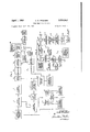
1' TIME MEASURING SYSTEM original Filed April 25. 1951 8 sheets-sheet 7 F I6. /O SQENCE 0E RELAY OPERATION T /NTERVAL NR, NR2 NH3 69 F/G. .9 T, c/ osEo OPEN OPEN 5a T2 OPEN cLosEo oPEN T3 OPEN OPEN c1. osEo 70 7 cLosEo OPEN OPEN T5 OPEN cLosEo OPEN STEP'UP T6 oPEN OPEN c/ osEo TRANsEo/QMER R7; 75l eh: AM
T0 60 F/L. SUPPLY IMPL/5E F/G- GENERATOR NEGA r/vE PART l /Ta Mo/c/T GATE mc. TUBE coNTRoL couNTER AND oEv/cE REG/:TER 131y coNNEcT/oNs 0W To L/NE M011 P455 a/aalaauiasl l Nl c goo E/LTER ouTPuT Enos s Kc. sENo .Mc/fs Accu/MTE souncE 0E F/xEo EnEouENcyfq VAR/ABLE /NVE/WOR osc/LLAToR K. W. PFLEGER 77- 96.5 kc. BVl
ATTORNEY April l, 1958 K. w. PFLEGER TIME MEASURING SYSTEM Original Filed April 25. 1951 8 Sheets-Sheet 8 anun run/tenante sYsrnM Kenneth W. Ptleger, Ariington, N. I., assigner to Bell Telephone Laboratories, Incorporated, New York, N. Y., a corporation of New Yori:
Griginal appiieatiun April 25, 1951, Serial No. 222,832,
now Patent No. 2,'7tltl,l33, dated `lanuary 1S, 1955. Divided and this application November 1t), i954, Serial No. 468,075
Claims. (Cl. 324-68) This invention relates to time measuring systems with particular emphasis upon improving the accuracy of such a system in the presence of noise currents which tend to interfere with the application of electrical counting methods to the measurement of time intervals.
An object of the invention is to sum up electrical counts during a succession of recurrent substantially equal time intervals to obtain an average value for a single such interval.
A feature of the invention is a control system for counting the individual time intervals as well as the total number of cycles of a standard wave source occurring during the intervals and for automatically stopping both counts when a desired number of intervals have occurred.
Another feature is a noise indicator useful in determining how many intervals should be counted in order that the average time per interval may be determined with a desired degree of accuracy.
This application is a division of eopending application Serial No. 222,832, filed April 25, 195i, now United States Patent No. 2,790,133, issued January 18, v1955.
in the figures:
Fig. l is a single-line schematic diagram of an illustrative system embodying the invention;
Fig. 2 is a single-line schematic diagram of an illustrative sending device;
-Fig. 3 is a group of illustrative oscillograms of currents in various circuit branches of the system of Fig. 2;
Fig. 4 is a single-line schematic diagram of an illustrative receiving device;
Figs. 5 and 6 taken together provide a double-line schematic diagram of an illustrative receiver in greater detail than shown in Fig. 4;
Fig. 7 is a group of illustrative oscillograms of currents in various circuit branches of the systems of Figs. 4, 5, and 6;
Fig. 8 is a group of enlarged oscillograms of currents in certain circuit branches in the systems of Figs. 4, 5, and 6;
Fig. 9 is a schematic diagram of a noise indicator;
Fig. l() is a tabulation of a sequence of relay operations involved in the operation of the noise indicator of Fig. 9;
Fig. ll is a schematic diagram of an alternative Vgating system for use at a sending terminal;
Fig. l2 is a schematic diagram of a gate control circuit employing a pentagrid vacuum tube; and
Fig. i3 is a schematic diagram of a portieri of an alternative receiving arrangement.
General method and apparatus In the disclosed system involving the present invention, there is employed a method of measuring envelope delay distortion as applied over a straightaway circuit or line, which comprises (a) sending periodically onto the line to be measured a pulse of reference frequency tone and a pulse of comparison or measuring frequency tone, one after the other, preferably with restricted sidebands,
@rates Patentice (b) counting the time eiapsingbetween arrivals of particular amplitudes of these pulses envelopes at the receiving end, and (c) averaging the results of a multiplicity of such counts when it is desired to reduce fortuitous effects such as caused by noise. The averaged count may be automatically indicated; and successive indications, each taken with a different measuring frequency and using the same time interval between sent tones, give substantially the envelope delay distortion vs. frequency characteristic except for a constant delay which is usually unimportant. lf the absolute delay is desired, it can be obtained when measuring is doneon a loop rather than on a straightaway basis.
Usually the narrower the range to which sidebands yof the measuring (variable) frequency signal are restricted the better, as the delay measured is then more nearly the same as the theoretical value ri/dw, except that the received envelope wave is then so gradual in slope that it is very diilcuit to measure time accurately to a particular point on the wave. As a compromise in a telephoto circuit, e. g., it is practical to receive a signal spectrum about cycles wide from the line having sidebands each 25 cycles wide. The sent rwaves envelope is rounded, closely approximating the function where c is a constant and t has values from .02 second to -l-.OZ second. Outside this range of t the envelope is zero until time for Athe next mark. This gives rise to a wide band of frequencies but the energy Outside the 50 cycle hand is small. Due to the cut-off of the receiving band bandpass ilter, the received envelope departs somewhat from that of the sent wave.
The sidebands of the reference frequency signal need not be restricted to such a narrow band as 50 cycles, because it is not necessary that its delay approximate dpr/dw. Any delay value is satisfactory for vthe reference pulse so long as it is constant. However, the greater the restriction of bandwidth, the easier it becomes to use measuring frequencies close to the reference frequency without erroneous operation of selective receiving circuits due to overlapping of frequency spectra of these tones. By using wide sidebands forthe reference tone and by giving it a steep wave front the need for much ampiiiication of the reference wave at the receiving end diminishes, as discussed below. Of course, the frequency spectrum of the reference tone should not contain much energy in the frequency range used for the measuring' tone, and consequently it is then diicult to measure delay distortion very close to the reference frequency. The use of two reference frequencies iS then generally necessary in order to obtain a complete delay distortion characteristic over all parts of the desired frequency range. Although the illustrative examples disclosed hereinafter do not use wide sidebands, this possibility is available in case one wishes to trade cost and weight of apparatus for the slight inconvenience of using two reference frequencies.
In the event that a 50 cycle bandwidth is used for both reference and measuring frequency marks, one may use measuring frequencies as close as about lcycles to any reference frequency. Furthermore, by using two different reference frequencies successively itis possible to obtain the delay distortion anywhere in the pass band of the line, when the delay distortion characteristic obtained with one reference frequency is modified by a suitable constant so that one continuous characteristic results when both are plotted on the same graph.
In the counting mechanism, to measure the time interval between the arrivals of particular amplitudes ,of the reference and measuring tones, measuring preferably is done between peak values `of the detected envelope Waves assassin of these tones because small amounts of level variation or selective attenuation on the line do not appreciably affect the mechanisms ability to discern the instants of maximum current. These instants are easily recognizable after passing the detected envelopes over a differentiating circuit because the latters output wave passes through zero at each maximum of the received wave, and the rapid change in sign of the differentiators output is suitable for the precise operation of trigger circuits for starting or stopping an electronic counter.
In order to insure still more reliable operation of trigger circuits the transitions in the differentiators output wave may be greatly amplified, as is accomplished partly by nonlinear coils which generate a sharp impulse of high voltage, and partly by linear amplification.
Separate amplifiers and diferentiators may be used for the two detected signals, although some saving in cost may result from a reduction in such apparatus, such as by the use of wider sidebands for the reference frequency signal as explained above.
Although an electronic counter measures delay precisely in one observation, the value may be influenced by interfering effects such as caused by noise. Therefore it is generally advantageous to design the counter so that it makes a number of delay measurements and indicates the average value.
Outline of illustrative system Fig. 1 is a simplified schematic diagram of an illustrative system having the basic elements required in the practice of the invention. Sinusoidally-enveloped pulses of a suitable high frequency carrier are produced at accurately timed intervals at the sending end of the transducer 1 to be measured, such as a line by means of a pulse repetition frequency source 2 of frequency such as 25 cycles reacting with a carrier oscillator 3, of frequency such as 97,000 cycles, in a first modulator d. The resulting modulated wave is impressed upon a second modulator 5 along with selected and timed pulses of standard and variable comparison frequency oscillations of uniform duration from oscillators 6 and 7 respectively. The pulses of standard frequency are under the control of a first gate 8 and those of the variable frequency under the control of a second gate 9, both gates being operated by a gate control device 10 which in turn is under the control of the low frequency source 2. The device i0, upon being manually started by the operator, first opens gate 8 to pass one pulse of standard frequency, then closes gate 8 for a selected number of pulse intervals, generally only one pulse interval, as in the illustrative system, then opens gate 9 and passes one pulse of comparison frequency,
closes gate 9 and holds both gates closed for a selected number (one or more) of pulse intervals and repeats this series of operations until shut down. The modulator 5 shifts the standard and variable comparison pulses downward in frequency to the desired values of frequency with which the transducer 1 is to be tested, for example, the standard pulses may be shifted to 3000 cycles and the variable frequency pulses to the range 20() to 20,000 cycles, a low pass filter 34 being inserted between the modulator 5 and the transducer 1. At the receiving end of the line a band filter 11 selects the 3000 cycle pulse which is thereupon translated into a sharp impulse by means of a detector 12, a ditferentiator 13 and an impulse generator 14. To handle the pulses of variable frequency efficiently it is usually preferable to shift them to a common frequency band as by means of a frequency shifter 15 controlled by a variable frequency oscillator lo. The common frequency may advantageously be placed at 97,000
'cycles in the illustrative example. The 97,000 cycle resulting pulse is translated into a sharp impulse by means of a detector 17, a ditferentiator 18 and an impulse generator 19. The first impulse upon the generator 14 is used to actuate a start-stop mechanism 20 which in turn actuates a gate device 21 which connects a standard counting cycle generator 22 to a cycle counter 23 which counts cycles from the generator 22 as long as the gate 21 remains open. The next impulse, which cornes from gen erator 19, shuts off the counting cycle generator, and, registers a count of one on a sample counter 24. When the last sample has been received and its number of cycles counted, the sample counter 24 stops the counting process by actuating the start-stop mechanism 20 to close the gate 21. The total count is shown on the count indicator 25, and is an automatically averaged value of all sample counts, as explained more fully hereinafter.
Sending apparatus The purpose of the sender is to transmit to the sending end of the line under test successive modulated spurts of reference and variable comparison frequency separated by xecl time intervals of zero current as shown by the oscillogram of current I7 in Fig. 3. The reference frequency as illustrated is (97 lie-fa) where fa may have any convenient number of fixed values, and the variable frequency is (97 lio-fb) in the example shown. These two voice frequencies are the result of heterodyning in the example hereinafter described. The envelope wave of these spurts is substantially sinusoidal as explained below, and resembles a 25 cycle wave in the system. The duration of each spurt is .04 second when the modulating wave is 25 cycles. The time elapsing between the peak value of the reference tone and the peak value of the next following spurt of variable frequency tone is assumed to be fixed, at .08 second. Therefore there is zero output during .04 second of this interval. This interval may be made greater if desired depending upon whether the envelope delay in the line is appreciably greater at the reference frequency than at any variable frequency used, it being necessary that these pulses shall not overlap at the receiving end of the line.
The choice of the time elapsing between the peak value of the variable frequency tone and the peak of the next succeeding reference frequency spurt depends upon the amount of delay distortion to be measured, since it is necessary that the spurt of variable freq ency tone shall not overlap or run into the spurt of reference frequency tone at the receiving end of the line. it is evident that the duration of the zero current interval following a pulse of variable frequency at the sender output should about equal the mMimum value of delay distortion to be measured.
Illustrative sports or pulses are shown in Fig. 3 as current I7 and in order to obtain current l?, the sending device may be shown schematically by thc single-line diagram in the upper portion of Fig. 2.
In Fig. 2, a source 216 of accurate frequency provides the input wave of a multivibrator or frequency divider 27 whose output is the first modulating frequency, for example, 25 cycles per second in the case of certain telephotograph circuits.
The 25 cycle wave passes over a hybrid coil 30 and one output thereof is connected to one input of the first modulator 4. The other input of this rnoduiator an accurate high frequency, for example 97 kilocycles obtained either as a harmonic of the accurate source 26 through the connection 29 as shown (or from the freqic v divider 27). The value 97 kilocycles is assumed for rustratirc purposes. A narrow bandpass filter 31 is shown at the output of thc first modulator sidebands passed by this filter are narrow so that the current I3 at its output has only three frequencies: 96.975, 97.0, and 97.025 kilocycles. The amplitudes of cycics per second and 97 kilocycles applied to modulator' 4 preferably are adjusted so that I3 is 100 percent modulated as shown in the oscillogram of Fig. 3. If the control source Zu is a 50 cycle pcrpsecond tuning fork the connection 29 may be used,
97 lrilocycles being the l940th harmonic of 50 cycles per second. This may require several stages of harmonic cause it is practically unchanged over the range of testing frequencies.
The narrow bandpass filter b of approximately 50 cycle width is used in the signal shifter to reduce the line noise and other disturbances if present.
The bandpass filters 22 and for two reference frequencies are also of about 50 cycle width when the sent pulses of reference frequency are thus restricted in frequency spectrum as this favors measuring fairly close to the reference frequency without appreciable error.
The low pass filters and 54- immediately following the respective de.ectors l2 and i7 consist of series resistors and shunt condensers because inductances at high levels are apt to be nonlinear and to cause varying effects as the level changes slightly. These filters suppress the carriers. No wave shaping is required of these filters due to the wave shaping action of t ie sending bandpass filters.
Currents i111 i12 are substantially proportional to the slopes of currents lg and I11, respectively, due to the differentiating effect of series condensers C11 and C12, which respectively perform the functions of the differentiators i3 and 18 of Fig. 4.
Coils L21 `and L22 are nonlinear and operate to produce sharp wave fronts in currents T51 and g so that the voltages across resistors R21 and rise from O to 8 volts in about two microseconds. The optimum values for circuit elements connecting to these nonlinear coils may be found by trial.
Iuductances L11 and L12 help to suppress the carriers and prevent discharge of condensers C21 and C22 toward the source. These inductances should be substantially linear. Each may consist of one or more retard coils. The inductance of such coils should be determined experimentally to obtain the desired maximum amplitudes for 111, and i12 with a minimum of input power and without excessive transients. Initial fluctuations during the build up of T or i12 are not wanted as they may cause unwanted pulses in lm and T52 ahead of the desired times which might give false operation of gas tubes.
A Zero reset switch S11 is provided and when this has been closed momentarii gas tube G. il is not firing and a neutral relay Nlr is released so that a pulse of 1 11 is transmitted over the contact of NR4 and resistor 1-21 to the grid of gas tube G. T. 2l which res to open the vacuum tube gate 3S.
The next succeeding pulse in im is transmitted over resistor i'31 to the grid of gas tube G. T. 3l which tires to close the gate. Accordingly the mesacycle current 113 which passes the gate has the duration T1. This is equal to the time interval elapsing between the sharp rises of the respective pulses in T51 and T52 provided currents 21 and :'31 risc abruptiy with equal slopes to full value when the respective gas tubes fire.
A relay 5R31 is necessary in series with the plate of gas tube G. T. 3T. which operates to cut off its plate voltage from source E11 and extiuguishcs both gus tubes very soon after gate closure.
A relay Slim, having substantially identical winding impedance to that of 8R31, is provided in the plate circuit of gas tube G. T. so that both plate circuits have substantially identical transient responses. The windings of 8R21 and 5R31 may be shunted by small condensers so as to obtain the nearest approach to rectangular on and off switching of the gate. The contacts of relay 8R21 are open at the tiring instant of gas tube G. to make sure that tube G. T. 2l tires before tube G. T. 3i., but close shortly thereafter to permit .ring of tube G. T. 3l on the next pulse of T52.
The megacycle pulses in T13 are shown again to an enlarged scale in Fig. 8. They may be passed through a wave Shaper 65 to produce negative pulses of the same fundamental periodicity, as shown in the oscillogram of 114.
ers B. C. 21, B. C. 22, et cetera. In some cases, the
Such pulses are suitable for operating binary count- Shaper 65 is not needed, the binary counter operating satisfactorily without the shaper. The Shaper may be made of either tube circuits or varistor circuits, or a copper oxide varistor with a direct-current bias may be used to pass short pulses of only one polarity.
The counting mechanism, described below keeps adding up the number of megacycle pulses it receives not only during time interval T1 but also during T2 and succeeding time intervals measured until a predetermined number of such intervals have passed whereupon a pulse is received by the grid of a gas tube G. T. lll from an auxiliary series of binary counters, B. C. 11, B. C. 12, et cetera, which count the number of positive spikes in 151. This pulse fires the gas tube G. T. 11 and its plate current operates the relay NR1 to stop further spikes in 151 from acting on the counters, at which time the counter indication becomes stationary and may be read and recorded by the operator. Operation of NR4 should not occur until at least .04 (N -l) second has elapsed following the iinal spike in T51, and must be complete before .04N second has elapsed, in order to allow the gate to remain open for the longest necessary value of T and to make sure it does not open after the last value of T. N is the number of reference frequency spurt intervals between the envelope peaks of successive reference frequency spurts. Therefore, relay NR4 should be slow acting and its slowness should be adjustable if N is varied.
The restoring of all counter circuits to the zero condition is accomplished by pressing the reset key S11 which operates reset relays 66 to make suitable voltage changes in the power supply of the counter stages, as discussed below.
The circuits of relays NR11, NR21, and NR31 are provided for the purpose of driving a noise indicator as described below. This indicator detects variations in engths of successive spurts of the current 113. When these variations are excessive, the number of samples of the time intervals T1, T2, T3, et cetera, averaged by the megacycle counter should be increased as described more fully below.
The number of sample averaged is controlled by a set of switches S32, S64, S1211, and S255. When all these switches are closed to the left, 512 samples are averaged. When one of these switches is closed to the right and the others are closed to the left, the number of samples averaged is the same as the subscript on the designation of the switch which is closed to the right.
The time which is required for the counter to average a given number of samples is about equal to that number multiplied by .04N second.
A wave Shaper 67 is also shown for inverting pulses T51 to produce the current pulses 115 used to drive the auxiliary counter. Pulses in 151 when inverted may be suitable for driving this counter. Therefore, the wave shaper 67 may be nothing but an inverter, for the purpose of changing positive pulses into negative pulses similar to 114.
in case the sent reference tone is given wider sidebands, bandpass filters 62 and 63 should be just wide enough to pass them. A tenfold increase in these sidebands permits the received reference signal to build up about ten times as fast and changes the shape of I9 from sinusoidal to nearly rectangular. The differentiated current then consists of positive and negative spikes. By making use of one or the other of these spikes to lire G. T. 21 and to operate the auxiliary counter, one can omit L11, L21 and condenser C21 and probably decrease the size of amplifier 59 and detector l2. The values for R21 and for the low pass filter 4S would be changed, the resistors being much smaller as they need not dissipate as much heat.
Electronic counters, trigger circuits, gates, et cetera, have been used for other purposes. Consequently no detailed explanation of these elements is considered necessary. Electronic counters are described by C. B. Leslie, Megacycle Stepping Counter, Proceedings Institute Radio Engineers, volume 36, No. 8, August 1948, pages 1030 to 1034.
Counting mechanism It is assumed in the system illustrated that during a time interval T ranging in duration from about 40,000 to 40,000 (N l) microseconds, a precisely one megacycle current flows from the oscillator 22, Fig. l, suitable for operating an electronic pulse counter. The time interval and the one megacycle current iiow are repeated periodically, each such interval being separated by a short time of zero current. Due to small amounts of line noise not under control, slight ortuitous variations exist in the value T from one repetition to the next. In order to reduce the effect of these, and to obtain a better value of T, it is desirable to add and average a number of separate measurements of T. in accordance with the invention, apparatus is provided to automatically indicate the result in microseconds.
Let 2n denote the approximate number of repetitions of repetitions of T which should be averaged in order to reduce the fortuitous effects to a negligible amount, the value for u being calculable for any small amount of noise as explained below. The megacycle pulses of 11.2 in Figs. 5 and 6 are made to operate first on a binary electronic counter comprising n pairs of (or n double) tubes. The output of the binary counter is connected to a six stage decimal counter. The latter counter registers a digit about once in each 2n microseconds. The iinal reading of the decimal counter is the desired average value of T. v
Averaging of a plurality of measurements of T is eiected automatically by adjustment of a scale factor associated with the counting mechanism. An average being by deiinition the sum of m readings divided by n1 and the sum is equal to m times the average. For example, if the sum of eight readings is 1,600,000, the average is 200,000. Hence, if the counter counts once fory every eight cycles of the megacycle current, the result of impressing l,600,000 cycles upon the counter is an indicated count of 200,000 which gives the average directly eX- pressed. Also, if there are a total of 6,400,000 cycles impressed upon the counter in the course of 32 readings, average reading again 200,000, the counter may be arranged to count once for every 32 cycles, giving an indicated count of 200,000, thus once more directly indicating the average. By using such a scheme, the average value as indicated is independent of the number of samples averaged.
it is evident that when 11:5 there are 32 samples of T averaged and since sampies of T occur every .2 second when N25 the running time is 6.4 seconds. lt has been determined 'oy computation that in the case of a telephotograph line on which there is a normal or average amount of random noise here assumed to be like thermal noise, the measuring error represented by the average of 32 val-ues of T has a standard deviation of 8.2 microseconds, which should usually be satisfactory precision in measuring telephotograph circuits. Such a normal or average amount of thermal noise is sometimes referred to as a thermal noise level of 35 dba with telephoto weighting at the zero level point of a telephotograph line. The unit used in expressing the noise level is adjusted decibels, abbreviated dba, and refers to the reading olf a noise measuring set such as the Western Electric Companys No. 2 type described in Bell Laboratories Record, March 1936, volume i4, page 233, when used with an appropriate equalizer designed to weight the disturbing effect of noise currents of different frequencies and durations upon a telephotograph circuit, the noise measurement being made at the Zero level point of the line.
Experience with telephotograph operation has indicated that the highest tolerable limit `of thermal noise is reached at 45 dba or l0 decibels above the normal or average essere@ noise measuring set lthis time T1. and NR3 are then open as shown in the table.
condition. When the noise is at the highest tolerable limit, the number of values of T which must be averaged to obtain the same standard deviation of error is ten times as great, or 320. In the binary scale the lowest suflicient value of n is 9, requiring the averaging of 512 values or" T, since with n equal to 8, only 256 values of T would be averaged. Accordingly the binary counter needs to have 9 double tubes or stages such as B. C. 2l to B. C. 29 in Figs. 5 and 6, so that n may be varied by desired amounts between 5 and 9, yusing switches S32, S64, S128, and S256 as described above.
Noise indicator Noise on the line may reduce the accuracy of the timing of an interval by distorting, lengthening, or shortening of the pulses of T2 of Fig. 7, which in turn affects the shape of the detected pulses i9 and T11, and displacesfthe zero points of i12 and i12, and hence atects the spacing between the impulses T51 and i511. The net result is that either too many or too few cycles of the standard frequency are included in the intervals T1, T2, et cetera, of 112. The accuracy in the presence of line noise may be improved by including a large number of intervals in the cycle count. The more the effect of line noise, the more intervals should be included. As the eiect of line noise is random, it is very likely to make itself evident by making adjacent intervals unequal. The more noise, the more inequality is likely to be found.
Although one may compute the number of values of T which should be averaged when the line noise has a certain value, it is advantageous to have a meter which indicates this automatically.
In Fig. 5 it is shown that the output of. the vacuum tube gate 38 is tapped by a branch circuit delivering megacycle power to the noise indicator 58 shown simpiy by a box in this figure but shown more in detail in Fig. 9. Therein leads 63 and a step-up transformer 69 impress a high megacycle voltage upon a rectifier 70 which may charge either condenser C71 or C72 over a high resistance R71. Therefore the charge on either condenser is proportional substantially to the charging time which is the same as the duration of a spurt of megacycle current such as T1 or T2, et cetera.
As shown by the table of Fig. l0, a neutral relay NR1 has closed contacts during time interval T1, corresponding to the spurt of megacycle current T1 in the oscillogram of Fig. 7. The condenser C71 is charged during The contacts of 'two other relays NR2 Shortly thereafter the contacts of NR1 open and this is followed by closure of contacts of relay MR2 so that during time interval T2 the condenser C72 is charged. After the end of interval T2 the contacts of NR2 open. Shortly after this the contacts of relay NRa close which permits both condensers to discharge simultaneously to ground through a pair of rectiiers '7i and 72 and resistors R72, R73, and R74. The resistance R72 is adjusted so that the alterhating-current meter reads zero when the two condenser discharges are equal as when noise is absent. Then subsequent inequality of duration of two adjacent spurts of megacycle current will cause unequal charges upon condensers C71 and C72, and during discharge will produce meter torque about in proportion tothe difference between the duration of T1 and T2. The meter should be sluggish as of the thermocouple type and may be calibrated in terms of the exponent n required to satisfactorilyaverage out the effect of the noise. (it would also be possible to operate switches S32 Sai, S122, and S256 automatically from the meter with the help of marginal relays, not shown.) Condenser discharge cannot occur until relay NR3 closes contacts because neither tube 71 nor 72 will conduct current from filament to plate. The tubes 70, '71, 72 are served by a filament supply transformer '74.
In order to insure closing or opening of contacts of -aimants l1 relays NRI, NR2, and NRS to completely include all of the respective time intervals indicated in Fig. l0, various means can be used to activate the relay windings. One method is next described which uses three auxiliary neutral relays Nlll, NR21, and NR31 shown in Figs. 5 and 6.
Before the power supply En in Figs. and 6 is turned on, relays NRJ NRzl, and NR31 are not operated and all their moving tongues are in the down position. After E11 is functioning, the operator starts the noise indicator by momentarily closing a start switch S12 which permits current to llow from En over tong-ue e2 of relay NR21 through the winding of relay NR11 to switch S12 and there to ground. This relay then operates and current continues to flow in its winding to ground by way of tongue a1 after the start switch is no longer closed.
The operator may next press the zero reset switch Sn and the counting mechanism starts. During the entire first pulse of megacycle current in the interval T1 current in ows through relay NRll as shown in the oscillograms, and consequently relay NR, is also operated due to closure of Contact by tongue d1 of relay NRI1 and a connection 75 indicated in Figs. 5, 6, and 9.
Shortly after the interval T1, relay 8R31 operates to ground its upper tongue momentarily whereupon current i22 flows from source E11 over tongue e3 of relay NR31 through the winding of relay Nfzl, tongue b2, tongue c1, upper tongue of relay 5R31 and to ground. Accordingly relay NRzl operates and remains operated after release of 8R31 because of current 1'22 now flowing over tongue a2 to ground. During operation of relay NR21, tongue a2 makes contact before tongue b2 breaks contact. The make before break feature can be obtained by suitable mechanical design. Operation of NR21 opens the contact of tongue e2 so that relay NRI1 releases and in falls to zero as shown in the oscillograms of Fig. 7.
At about the same time as relay NRI1 releases, relay Nlll releases as relays NRI, Nllg, and NR3 are all made fast release relays. However they are made slightly slow to operate so that closure of Contact does not occur until after the previously operated relay in this group has released. Slow operation may be attained when necessary by inserting a separate inductance (not shown) in series with the winding of each relay to be slowed.
Operation of relay NR21 permits current to flow over relay NRE to ground by way of tongue d2, and a connection 76 shown in Figs. 5, 6, and 9 and shortly thereafter relay NR2 operates. The timing is such that it operates after NRl has released and before the start of time interval T2.
Shortly after time interval T2 another brief closure of the upper contact on relay 8R31 occurs. This time current 1'33 flows from source E11 over tongue e1, winding of NR31, tongue b3, tongue c2, to upper tongue of relay 8R31, and thence to ground.
Immediately relay NR31 operates and continues to remain operated due to current 1'33 flowing over tongue a3 after release of 5R31. (Tongue a3 makes contact just before tongue b3 opens Contact.)
Operation of relay NR31 stops current i22 due to opening of the contact of tongue e3. Due to operation of tongue d3 and current through a connection 77 the operation of relay NR3 takes place shortly after NRZ releases caused by opening of contact by tongue d2.
The next closure of relay 8R31 permits the rise of in again by way of tongue e2, winding of NRll, tongue b1, tongue c3, and upper contact of 3R31. After 8R31 releases, if, continues by way of tongue a1 and 33 is stopped by opening of contact el. (Tongue a1 makes contact just before tongue b1 breaks contact.) This concludes one complete cycle of events in the noise indicator auxiliary relays, and again places condenser C71 in condition for charging just as soon as relay Nltl operates due to closure of tongue d1.
Spark killers K1, K2, K3 K11 are shown to reduce relay contact erosion. Condensers and resistances should be adequate to quench the sparks but should not slow down the current decay too much.
Alternative gating systems for Sending terminal An electric counting circuit shown in Fig. 1l and comprising a plurality of vacuum tubes and varistors may be used in place of the gas tubes and relays to reduce weight and cost of maintaining relay contacts. The oscillograms in Fig. 3 apply to Fig. 1l as regards currents shown in the latter, except for the insertion of a one-way device 78 so that only the negative pulses of current l5 are received by the gate control device of Fig. ll.
An N-digit counter 79 of any suitable known kind may be used. The operation of the counter is such that during the first period of .04 second corresponding to a de sired rectangular spurt of fixed high frequency fa in the current I5, the potential on output lead 3l of the counter 79 is positive with respect to that on lead C. This causes gate 8 to open lbecause direct-current passes over its varistors in the forward direction. At other times the potential of lead 8l is less than that of lead C-and gate 8 is closed. During the third period of .04 second corresponding to a desired rectangular spurt of variable high frequency fb, gate 9 is similarly operated, but at other times it is closed. Gate 8 may contain a plurality of varistors 86 and a resistor R83 and gate 9 may contain a plurality of varistors 87 and a resistor R81 as shown.
Values for resistors R81 and R83 are to be chosen by trial to obtain a high ratio between amplitude of gate output when open as compared to the closed condition, 35 decibels or more usually being satisfactory. When necessary to obtain a higher ratio, a multiplicity of such gates may be used in tandem, controlled by the same gate control output leads.
Switches may be provided by means of which one can open leads 81 and 83 and insert positive direct potential upon either gate for the purpose of obtaining a continuous current of either frequency fa or fb. This is useful when adjusting the sending levels.
Some care will have to be used in order not to render the counting mechanism inoperative due to the gate varistors having too low an impedance in the forward direction. If trouble is experienced in this respect one may use a pentagrid gate so that the control lead goes to a high impedance grid, as shown in Fig. l2.
Fig. l2 shows the alternative form of gate using a pentagrid tube 88. Lead 8l or 83, as the case may be, from the counter 79 is connected to grid 163 of tube 8S and lead C is connected to grid 10S. The input from either source 40 or oscillator 1l is connected through a transformer to the grid 101 and the output is taken from the anode. Grids 102 and 104 are connected together and function as screens between grids 101 and lr03, and 1.03 and 105, respectively. An l8-volt biasing battery 200 shown in series with lead C keeps the gate closed during times when lead 81 or 83 has no positive potential. This biasing battery could also be in series with lead 81 or 83 instead of lead C, or could be partly in each lead so long as it is poled to make grid 103 more negative than grid 105.
Alternative receiving arrangement Fig. 13 shows a portion of a receiver similar to the arrangement of Figs. 5 and 6 except that all relays but those in the reset device are eliminated. The latter relays could also be eliminated if one would put their contact leads instead on a multiple contact switch including contacts of S11. From the line to the ditferentiators the system is the same as that of Figs. S and 6. Also, the megacycle counter and indicator 23 in Fig. 13 is the same as the binary counters 21 through Z9 and the decimal counters with indicators in Figs. 5 and 6. The auxiliary binary counter 24 in Fig. 13 is the same as the auxiliary binary counters 11 through 19 in Figs. 5 and 6. The impulse generators 14 and 19 are the same in both figures except that in Fig. 13 negative pulses instead of positive pulses appear at their outputs, due to a reversal in the leads at their inputs, since negative pulses are required for operation of certain known types of binary counter. Counters 24, S9, and 115 are shown as of such type, while counter 23 is shown as op'eratable on positive pulses, or when 11.1 consists of negative current as in Fig. 8, counter 2.3 operates on negative pulses.
The desired negative voltage pulses E51 and E52 have shapes similar to the current pulses 151 and 152 shown in oscillograms in Fig. 7 except for the change in sign.
When the power is rst turned on, gas tube G. T. 111 will not be firing, but it tires when a sufficient number of pulses of E52 have acted on the auxiliary counter to produce a stop pulse at its output which acts on the grid of G. T. 111 through the associated input transformer. Counters 23 and 115 stop when G. T. 111 res as explained below.
Before a delay measurement is made, one must press key S11 to operate the reset device which places all counters in the zero condition in the manner hereinabove described. It is necessary that all counters shall be reset to the zero condition before pulses of E51 or E52 are allowed Vto reach them. Therefore, key S11 is designed to make contact to the fast acting reset relays before plate current of tube G. T. 111 is cut olf by the key, in order that all counters shall reach the zero' condition before the plate current is cut off, which has the effect of removing negative grid bias from vacuum tube 114 and opening this vacuum tube gate to permit the next negative pulse of E51 to act on counter 115.
In case a pulse of E52 occurs ahead of said pulse in E51 and after opening of vacuum tube gate 114, that pulse of E52 can have no effect on B. C. 115 because with B. C. 115 on Zero the potential of its output lead 1 is less than that of its output lead which biases the grid of vacuum tube 151 negatively by about 22.5 volts and prevents plate current from owing therein due to the pulses of E52. Thus, it is evident that no pulse of E52 is received by any counter un-til the rst pulse of E51 has acted on B. C. 115 to operate this counter to the 1 condition so that lead l at its output is about 22.5 volts more positive than lead O which opens the gate consisting of V. T. 151. Resistors R22 and R22 may be provided if necessary to limit currentiowng from leads 0 and 1 so that changes in potential on these leads shall not aifect the performance of counter 115 through feedback action.
The next pulse of E52 may pass through the anodecathode circuit of V. T. 151 because the negative grid bias has been removed.
As soon as the negative pulse E52 reaches counter 115, the counter operates to close gate 21 and terminates the duration of the spurt of megacycle current. Succeeding pulses of E51 and E52 also respectively start and stop the megacycle current 113 in the same manner. The result is the same as in Figs. 5 and 6 in that the starting and stopping of the megacycle current occur respectively as the impulses in E51 and E52 build up.
The purpose of varistor V25 is to prevent pulses of E51 from operating the auxiliary counter 24 or the ternary counter 89 described below in connection with the noise indicator. Varistor V22 is provided to cut ol the output impedance of impulse generator No. 1 during a pulse of E52 so that the full effect of the pulse'actsl on' the counters.
In order to insure uniform action, the wave fronts of E51 and E52 should be steep and the counter 115 should be made fast acting the same as .fthe first stage of the megacycle counter 23 hereinabove described.
When the desired number of repetitions of themegacycle spurt has been obtained, the auxiliary counter has received a corresponding number of pulses of E52 and its last stage then sends out a pulse which tiresl gas :tube G. T. 111 as in the case of Figs. 5 and 6. In Fig. 13 the tiring of G. T. 111 causes a voltage drop across re sistor R25 which biases nega-tively the grid of vacuum tube 11d and prevents further operation of counters 115 and 23 inclusive due to succeeding pulses until after the operator has again pressed key S11.
Whenever a pulse of E52 passes through vacuum tube 151 to operate binary counter from the l to the 0 condition, the same pulse operates the auxiliary counter 24 with a signal similar to 115 of Fig. 7 except that it occurs at the end of the time intervals T1, T2, et cetera. Also, the same pulse operates a second auxiliary counter shown in Fig. 13 as ternary counter 89 for use in controlling gates 91, 92, and 93 of the noise indicator. These gates replace relays respectively designated as NR1, NR2, and NR2 in Fig. 9.
The gates 91, 92, and 93 are opened one at a time in the order mentioned for 'the duration of .04N second after the respective pulse of E52. N has the same meaning as in the previous description.
When gate 91 has opened, the megacycle current flowing through gate 21 after the next pulse of E51, can also fiow over gate 91, amplifier A1, and diode rectiiier 94 to charge mica condenser C24 through a high resistance R22 so that the nal charge on C21 when gate 91 closes on the next pulse of E52, is proportional to the duration of the megacycle spurt, for example, T1, in Fig. 7.
As soon as the yternary counter 89 closes gate 91, it opens gate 92, and during `the next spurt of megacycle current, mica condenser C25 is charged in a similar manner to C24, until its final charge is proportional to T2.
As soon as gate 92 has closed, the ternary counter 89 opens gate 93 so that both condensers C22 and C25 discharge simultaneously over one- way valves 96 and 97, respectively, and over resistors R22, R97, R22 and the alternating-current meter 9S. As described hereinabove the discharge circuit is balanced so that there is no meter indication when times T1 and T2 are equal. Since this noise indicator circuit will vary somewhat from time to time due to ltemperature changes in the condensers and resistances, et cetera, it should occasionally be readjusted for balance. Since it is not always possible to obtain a perfectly quiet line for use between the sender and receiver when making such adjustment, an inexpensive low frequency local oscillator should be provided in the receiver to provide signals with no fluctuation noise.
The plate Isupply for gas tube 111 as well as its grid bias battery (if used), are non-grounded in order not to interfere with the operation of the counters, all of which operate on a separate single plate supply which is assumed to have its negative terminal grounded.
As in the case of the meter 73 in Fig. 9, the meter 98 may be calibrated preferably in terms of the exponent n which determines the number of samples which should be counted to reduce to a desired degree the probable error of the measured delay time. It is to be understood that the above-described arrangements are illustrative of the application of the principles of the invention. Numerous other arrangements may be devised by those skilled in the art without departing from the spirit and scope of the invention.
While in the sample-counting stages and in the preliminary standard wave cycle stages, binary counters are shown and are desirable in order that the number of sarn- 15 ples may be readily variable in powers of two, it is nevertheless feasible to use ternary counters or counters based upon other numbers. Also, Wherever decimal counters are shown, counters using systems of numeration with other bases may be used instead. Where the number of events to be counted is xed, as in the noise measuring circuit of Fig. 13, there may be but one advantageous choice of the base of the system of numeration, for which reason the use of the ternary counter 89 may be preferred for controlling the three essential steps in the noise measuring operation.
What is claimed is:
1. In a time measuring system, a source of standard waves, means coupled to said source for passing successive trains of waves from said source and suppressing such Waves during the interval between said trains, a source of pulses, means for applying pulses from said pulse source to actuate said wave train passing means to pass a train of waves from said source of standard waves, means coupled to said Wave train passing means for counting cycles of Waves from said source of standard Waves passed by said wave train passing means, means connected to said pulse source for counting pulses therefrom, and means connected to said pulse counting means and to said wave train passing means for stopping the counting ofv both the standard wave cycles and said pulses when the number of said pulses reaches a desired value.
2. A time interval measuring system for recurrent intervals comprising means for producing recurrent starting signals and stopping signals which mark the beginning and end respectively, of the said recurrent time intervals, a source of standard waves, means for counting a desired number of starting signals, a lirst counting means for counting cycles of standard waves from said source actuated by each said starting signal and operating until deactivated by the next succeeding stopping signal, a second counting means actuated by said first counting means in a xed ratio whereby said second counting means registers a count of one for each n cycles of standard waves, means for adjusting the value of n and the desired number of starting signals in a desired relationship, means to stop the counting of starting signals and of cycles of standard Waves when the desired number of starting signals is reached, and means to indicate the total counts registered by said second counting means as a measure of time.
3. A time measuring system for recurrent time intervals comprising a source of recurrent starting signals alternating with stopping signals which mark the beginning and end, respectively, of the said recurrent time intervals, a source of standard wave cycles, a iirst counter connected to said source of starting and stopping signals and selectively sensitive to said starting signals, said counter providing an output pulse upon receipt of a lixed number M, of impressed starting signals, a second counter connected to said source of standard wave cycles under the control of said source of starting and stopping signals, said second counter providing an output pulse upon receipt of the same number M, of standard Wave cycles, a third counter connected to the output of said second counter, to count the output pulses delivered by said second counter, means to stop all of said counters after M of said recurrent time intervals have been completed, and means for indicating the total number of pulses received by said third counter.
4. A time measuring system for recurrent time intervals comprising a source of recurrent starting signals and stopping signals which mark the beginning and end, respectively, of the said recurrent time intervals, a source of standard wave cycles, a rst binary counter of n stages connected to said source of starting signals for counting 2n starting signals, a second binary counter of the same -number of stages connected to said source of standard wave cycles and controlled by said starting and stopping signals for counting standard wave cycles during the successive recurrent time intervals, a decimal counter operatively connected to said second binary counter for receiving therefrom one pulse for each 2Il standard Wave cycles, means for stopping all of said counters when 2n intervals have been completed, and means for indicating the total number of pulses registered by said decimal counter.'
5. In a time interval measuring system for recurrent intervals with reference to signaling transmission over a given line, means for supplying from said line a pulse which is composed of a group of waves of a given frequency and has a rounded envelope, said pulse corresponding to a predetermined time of each of said recurrent intervals, envelope detecting means connected to said supplying means, dilerentiating means connected to said envelope detecting means for producing an output which changes in sign in response to the occurrence of a maximum amplitude in said envelope, and means connected to said dilerentiating means for producing a sharp impulse in response to said change in sign.
References Cited in the tile of this patent UNITED STATES PATENTS 2,414,107 Kenyon Jan. 14, 1947 2,632,810 Nyman Mar. 24, 1953 2,700,133 Plieger Jan. 18, 1955
Priority Applications (1)
| Application Number | Priority Date | Filing Date | Title |
|---|---|---|---|
| US468075A US2829342A (en) | 1951-04-25 | 1954-11-10 | Time measuring system |
Applications Claiming Priority (2)
| Application Number | Priority Date | Filing Date | Title |
|---|---|---|---|
| US222832A US2700133A (en) | 1951-04-25 | 1951-04-25 | Measurement of relative delay of wave envelopes |
| US468075A US2829342A (en) | 1951-04-25 | 1954-11-10 | Time measuring system |
Publications (1)
| Publication Number | Publication Date |
|---|---|
| US2829342A true US2829342A (en) | 1958-04-01 |
Family
ID=26917192
Family Applications (1)
| Application Number | Title | Priority Date | Filing Date |
|---|---|---|---|
| US468075A Expired - Lifetime US2829342A (en) | 1951-04-25 | 1954-11-10 | Time measuring system |
Country Status (1)
| Country | Link |
|---|---|
| US (1) | US2829342A (en) |
Cited By (2)
| Publication number | Priority date | Publication date | Assignee | Title |
|---|---|---|---|---|
| US3026481A (en) * | 1957-09-30 | 1962-03-20 | Ibm | Synchronized time system |
| US5150337A (en) * | 1990-02-21 | 1992-09-22 | Applied Magnetics Corporation | Method and apparatus for measuring time elapsed between events |
Citations (3)
| Publication number | Priority date | Publication date | Assignee | Title |
|---|---|---|---|---|
| US2414107A (en) * | 1944-06-30 | 1947-01-14 | Sperry Gyroscope Co Inc | Electronic timing apparatus |
| US2632810A (en) * | 1951-02-02 | 1953-03-24 | Alden Products Co | Facsimile framing system |
| US2700133A (en) * | 1951-04-25 | 1955-01-18 | Bell Telephone Labor Inc | Measurement of relative delay of wave envelopes |
-
1954
- 1954-11-10 US US468075A patent/US2829342A/en not_active Expired - Lifetime
Patent Citations (3)
| Publication number | Priority date | Publication date | Assignee | Title |
|---|---|---|---|---|
| US2414107A (en) * | 1944-06-30 | 1947-01-14 | Sperry Gyroscope Co Inc | Electronic timing apparatus |
| US2632810A (en) * | 1951-02-02 | 1953-03-24 | Alden Products Co | Facsimile framing system |
| US2700133A (en) * | 1951-04-25 | 1955-01-18 | Bell Telephone Labor Inc | Measurement of relative delay of wave envelopes |
Cited By (2)
| Publication number | Priority date | Publication date | Assignee | Title |
|---|---|---|---|---|
| US3026481A (en) * | 1957-09-30 | 1962-03-20 | Ibm | Synchronized time system |
| US5150337A (en) * | 1990-02-21 | 1992-09-22 | Applied Magnetics Corporation | Method and apparatus for measuring time elapsed between events |
Similar Documents
| Publication | Publication Date | Title |
|---|---|---|
| US2405597A (en) | Frequency measuring system | |
| US2851596A (en) | Electronic counter | |
| US2433385A (en) | Submarine locating system | |
| US2414479A (en) | Impulse generator | |
| US2828482A (en) | Conversion systems | |
| US2725526A (en) | Electric line fault locators | |
| US2700133A (en) | Measurement of relative delay of wave envelopes | |
| US3723891A (en) | Frequency to voltage converter | |
| US2699464A (en) | Fundamental pitch detector system | |
| US2399668A (en) | Impulse duration responsive or indicating device | |
| US2829342A (en) | Time measuring system | |
| US2791746A (en) | High speed recorder | |
| US2414107A (en) | Electronic timing apparatus | |
| US2628267A (en) | Electric line fault locators | |
| US2638273A (en) | Dual-channel counting rate meter | |
| US2867767A (en) | Signal detectors | |
| US2699529A (en) | Electronic timer | |
| US2790142A (en) | Missing pulse indicator | |
| US3263064A (en) | Apparatus for determining the repetition frequency of pulse signals | |
| US3373245A (en) | Production of current of random variation | |
| US3040260A (en) | Coded pulse train spacing tolerance checker | |
| US3546585A (en) | Short duration signal burst frequency meter | |
| US2912579A (en) | Pulse width and repetition rate discriminator | |
| US2953746A (en) | Peak reading voltmeter for individual pulses | |
| US2870327A (en) | Electronic probability circuit |