US282590A - paek b - Google Patents
paek b Download PDFInfo
- Publication number
- US282590A US282590A US282590DA US282590A US 282590 A US282590 A US 282590A US 282590D A US282590D A US 282590DA US 282590 A US282590 A US 282590A
- Authority
- US
- United States
- Prior art keywords
- stricture
- catheter
- cutting
- knife
- section
- Prior art date
- Legal status (The legal status is an assumption and is not a legal conclusion. Google has not performed a legal analysis and makes no representation as to the accuracy of the status listed.)
- Expired - Lifetime
Links
- 208000031481 Pathologic Constriction Diseases 0.000 description 9
- 210000003708 urethra Anatomy 0.000 description 4
- 206010065584 Urethral stenosis Diseases 0.000 description 2
- 201000001988 urethral stricture Diseases 0.000 description 2
- 238000000034 method Methods 0.000 description 1
- 230000035515 penetration Effects 0.000 description 1
- 238000001356 surgical procedure Methods 0.000 description 1
Images
Classifications
-
- A—HUMAN NECESSITIES
- A61—MEDICAL OR VETERINARY SCIENCE; HYGIENE
- A61B—DIAGNOSIS; SURGERY; IDENTIFICATION
- A61B17/00—Surgical instruments, devices or methods
- A61B17/32—Surgical cutting instruments
- A61B17/320016—Endoscopic cutting instruments, e.g. arthroscopes, resectoscopes
- A61B17/32002—Endoscopic cutting instruments, e.g. arthroscopes, resectoscopes with continuously rotating, oscillating or reciprocating cutting instruments
Definitions
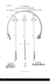
- FIG. 5 is a view in crosssection of the instruments represented in Figs. 1 and 3, the lines of section being-indicated at a; or.
- My invention is intended for operation up on cases of old or impassable stricture of the urethra, the difficulties of removing which by ordinary methods of cutting are well understood by surgeons. These difficulties arise mainly from the yielding or slipping of the tissues under the pressure of the cutting-instrument and the consequent uncertainty both in location and extent of the actual cut.
- My invention is designed to obviate this; and to that end it consists in the combination, with a suitable cutting-instrument, of devices whereby the part to be operated upon is maintained in a fixed position during the cutting, thus enabling the operator to limit the cut to the exact spot de sired, and to thoroughly sever the stricture.
- A (shown in Fig. 1,) is curved in form approximately to the arc of a circle, and should taper toward the end a. It is preferably provided with a removable clamp -handle, B, and is grooved longitudinally on the outer periphery of the are, as indicated in the cross-section in Fig. 5 at d.
- the second device is a straight tube, 0, such as shown in Figs. 2, 3, and 4-. This tube is also provided with a proper handle, D, and should taper somewhat toward the endc, whose orifice is, however, slightly larger than the point of the catheter A.
- the catheters shown in Figs. 2 and 4c have interior cutting devices, while that shown in Fig. 3 is intended for use in connection with a scalpel or ordinary surgical knife, and is grooved longitudinally on its exterior, as indicated by the cross-section shown in Fig. 5.
- the knife shown at f in Fig. 4 may be employed.
- This knife is a simple fiat blade mounted diametrically across the tube 0, and having its cutting-edge a short distance from the end 0.
- the cutting is effected by holding the catheter A firmly against the stricture and pressing the catheter C inward until the tissue at the place of stricture is forced into the orifice and against the edge of the knife by which the section is performed.
- the grooved catheter shown in Fig. 3 is used in connection with the catheter A, the grooves upon both being made to correspond when their tissue at the place of stricture is being held between them, as described.
- Both of these old devices differ from my present invention in that they do not provide any means for ho1ding the tissue to be severed on both sides of the stricture, and hence are open to the obj ectlons hereinbefore referred to and which it is my purpose to avoid.
Landscapes
- Health & Medical Sciences (AREA)
- Surgery (AREA)
- Life Sciences & Earth Sciences (AREA)
- Biomedical Technology (AREA)
- Nuclear Medicine, Radiotherapy & Molecular Imaging (AREA)
- Engineering & Computer Science (AREA)
- Orthopedic Medicine & Surgery (AREA)
- Heart & Thoracic Surgery (AREA)
- Medical Informatics (AREA)
- Molecular Biology (AREA)
- Animal Behavior & Ethology (AREA)
- General Health & Medical Sciences (AREA)
- Public Health (AREA)
- Veterinary Medicine (AREA)
- Surgical Instruments (AREA)
Description
(No Model.)
P. B. TUCKER.
URETHRAL STRIOTURE INSTRUMENT.
Patented Aug. '7, 1883.
FIG.1.
H65 INVENTORQ.
Q Me
wlmassss.
n. PETER$ Phnwmmgmaner. Wuhmglon. n. c.
rrEE TATES ATENT URETHRAL-STRICTURE INSTRUMENT.
SPECIFICATION formingpart of Letters Patent No. 282,590, dated August '7, 1883.
Application filed January 16, 1883.
To all whom it may concern:
Be it known that I, PARK B. TUCKER, of Hamilton, in the Island of Bermuda, have in vented certain new and useful Instruments for the Surgical Treatment of Urethral stricture.
The following is a specification of my invention, reference being had to the accompanying drawings, wherein Figures 1, 2, 8, and 4 are side views of the instruments whose combined use constitutes the essential feature. Fig. 5 is a view in crosssection of the instruments represented in Figs. 1 and 3, the lines of section being-indicated at a; or.
My invention is intended for operation up on cases of old or impassable stricture of the urethra, the difficulties of removing which by ordinary methods of cutting are well understood by surgeons. These difficulties arise mainly from the yielding or slipping of the tissues under the pressure of the cutting-instrument and the consequent uncertainty both in location and extent of the actual cut. My invention is designed to obviate this; and to that end it consists in the combination, with a suitable cutting-instrument, of devices whereby the part to be operated upon is maintained in a fixed position during the cutting, thus enabling the operator to limit the cut to the exact spot de sired, and to thoroughly sever the stricture.
I employ two holding devices, which, for convenience of description, may be termed catheters. The first of these, A, (shown in Fig. 1,) is curved in form approximately to the arc of a circle, and should taper toward the end a. It is preferably provided with a removable clamp -handle, B, and is grooved longitudinally on the outer periphery of the are, as indicated in the cross-section in Fig. 5 at d. The second device is a straight tube, 0, such as shown in Figs. 2, 3, and 4-. This tube is also provided with a proper handle, D, and should taper somewhat toward the endc, whose orifice is, however, slightly larger than the point of the catheter A. The catheters shown in Figs. 2 and 4c have interior cutting devices, while that shown in Fig. 3 is intended for use in connection with a scalpel or ordinary surgical knife, and is grooved longitudinally on its exterior, as indicated by the cross-section shown in Fig. 5.
The character of the cutting devices may be better explained by reference to the mode of (No model.)
operation of the combined instrument. An incision being made above the pubes in the manner practiced by surgeons for penetration of the bladder, the smaller end of the catheter A is inserted through the bladder into the urethra until the point a reaches the stricture. The opposing catheter C is then introduced in the ordinary manner through the external orifice of the urethra and pushed inwardly to the point of stricture. If, in the judgment of the operator, a circular cut is desirable, so as to excise a portion of the tissue, the form of lnterior cutting apparatus shown in Fig. 2 is employed. This consists of a knife, f, whose form is approximately the hollow frustum of a cone mounted firmly in a seat within the tube a short distance from the end 0. If transverse section only is necessary, the knife shown at f in Fig. 4 may be employed. This knife is a simple fiat blade mounted diametrically across the tube 0, and having its cutting-edge a short distance from the end 0. In either case the cutting is effected by holding the catheter A firmly against the stricture and pressing the catheter C inward until the tissue at the place of stricture is forced into the orifice and against the edge of the knife by which the section is performed. Should the operator desire to cut from the exterior, the grooved catheter shown in Fig. 3 is used in connection with the catheter A, the grooves upon both being made to correspond when their tissue at the place of stricture is being held between them, as described. An incision being then made into the urethra near the stricture, the point of the knife should be inserted into the groove of the catheter A, and the edge drawn along the grooves until the section is complete. It will be 0bserved that in all three instances the mode of operation is identical in so far as the above mentioned objects of the invention are concerned, since whether the cutting be effected within or by external section the tissue is grasped. and firmly held on both sides of the shown above in such combination. Furthermore, I am aware that it is not new tocombine with a catheter an interior cutting device and mechanism to protrude the same; nor is it new to provide the exterior surface of a catheter with a grooved guide. Both of these old devices differ from my present invention in that they do not provide any means for ho1ding the tissue to be severed on both sides of the stricture, and hence are open to the obj ectlons hereinbefore referred to and which it is my purpose to avoid.
Having thus described the nature and ob- Jects ofiny invention, what I claim herein as new, an d desireto secure by Letters Patent,
Publications (1)
| Publication Number | Publication Date |
|---|---|
| US282590A true US282590A (en) | 1883-08-07 |
Family
ID=2351799
Family Applications (1)
| Application Number | Title | Priority Date | Filing Date |
|---|---|---|---|
| US282590D Expired - Lifetime US282590A (en) | paek b |
Country Status (1)
| Country | Link |
|---|---|
| US (1) | US282590A (en) |
Cited By (1)
| Publication number | Priority date | Publication date | Assignee | Title |
|---|---|---|---|---|
| US20190180081A1 (en) * | 2017-03-31 | 2019-06-13 | International Business Machines Corporation | Analyzing writing using pressure sensing touchscreens |
-
0
- US US282590D patent/US282590A/en not_active Expired - Lifetime
Cited By (1)
| Publication number | Priority date | Publication date | Assignee | Title |
|---|---|---|---|---|
| US20190180081A1 (en) * | 2017-03-31 | 2019-06-13 | International Business Machines Corporation | Analyzing writing using pressure sensing touchscreens |
Similar Documents
| Publication | Publication Date | Title |
|---|---|---|
| US8377086B2 (en) | Surgical cutting instrument with distal suction passage forming member | |
| US9345488B2 (en) | Method of cutting tissue | |
| US8585724B2 (en) | Surgical cutting instrument with distal suction capability | |
| US6561998B1 (en) | Transluminal devices, systems and methods for enlarging interstitial penetration tracts | |
| US2749909A (en) | Biopsy knife | |
| US8579902B2 (en) | Devices and methods for tissue modification | |
| US20080234713A1 (en) | Shaver blade with depth markings | |
| US20050209624A1 (en) | Scissors for piercing and cutting anatomical vessels | |
| EP1923010B1 (en) | Trocar | |
| US5676012A (en) | Process for forming endoscopic shaver blade from elongate tube | |
| US20060116704A1 (en) | Tissue tract lancet | |
| US8696688B2 (en) | Method and apparatus for passing a flexible strand | |
| EP1101471A2 (en) | Cervical discectomy instruments | |
| JPH05253231A (en) | Tool for endoscopic surgical treatment | |
| JP2006502754A5 (en) | ||
| US20170354433A1 (en) | Device for plantar fascia endoscopy and soft tissue releases | |
| US282590A (en) | paek b | |
| EP2913014B1 (en) | Overtube | |
| US20220160389A1 (en) | Endoluminal punch system | |
| WO2020053684A1 (en) | Cutting tool for the vertical incision of a tendon | |
| US20250072924A1 (en) | Apparatus and methods of trigger digit release | |
| JPH05317324A (en) | Medical piercing tool | |
| US20120330339A1 (en) | Tissue cutting device, assembly and method | |
| US268039A (en) | John w | |
| CN207693643U (en) | deep fascia cutter |