US2812660A - Bullet trap - Google Patents
Bullet trap Download PDFInfo
- Publication number
- US2812660A US2812660A US456341A US45634154A US2812660A US 2812660 A US2812660 A US 2812660A US 456341 A US456341 A US 456341A US 45634154 A US45634154 A US 45634154A US 2812660 A US2812660 A US 2812660A
- Authority
- US
- United States
- Prior art keywords
- bullet
- liquid
- basin
- bullets
- trap
- Prior art date
- Legal status (The legal status is an assumption and is not a legal conclusion. Google has not performed a legal analysis and makes no representation as to the accuracy of the status listed.)
- Expired - Lifetime
Links
- 239000007788 liquid Substances 0.000 description 39
- XLYOFNOQVPJJNP-UHFFFAOYSA-N water Substances O XLYOFNOQVPJJNP-UHFFFAOYSA-N 0.000 description 12
- 230000035939 shock Effects 0.000 description 9
- 238000011084 recovery Methods 0.000 description 7
- 238000000034 method Methods 0.000 description 6
- 239000000463 material Substances 0.000 description 5
- 238000010304 firing Methods 0.000 description 4
- 238000010276 construction Methods 0.000 description 3
- 239000007789 gas Substances 0.000 description 3
- 239000000203 mixture Substances 0.000 description 2
- 230000035515 penetration Effects 0.000 description 2
- 230000001681 protective effect Effects 0.000 description 2
- 239000004576 sand Substances 0.000 description 2
- 230000002459 sustained effect Effects 0.000 description 2
- 238000012360 testing method Methods 0.000 description 2
- 230000002745 absorbent Effects 0.000 description 1
- 239000002250 absorbent Substances 0.000 description 1
- 230000009471 action Effects 0.000 description 1
- 230000001154 acute effect Effects 0.000 description 1
- 230000004888 barrier function Effects 0.000 description 1
- 230000008878 coupling Effects 0.000 description 1
- 238000010168 coupling process Methods 0.000 description 1
- 238000005859 coupling reaction Methods 0.000 description 1
- 230000003467 diminishing effect Effects 0.000 description 1
- 239000000428 dust Substances 0.000 description 1
- 230000000694 effects Effects 0.000 description 1
- 238000003780 insertion Methods 0.000 description 1
- 230000037431 insertion Effects 0.000 description 1
- 238000009413 insulation Methods 0.000 description 1
- 238000012423 maintenance Methods 0.000 description 1
- 230000007246 mechanism Effects 0.000 description 1
- 238000012986 modification Methods 0.000 description 1
- 230000004048 modification Effects 0.000 description 1
- 239000010902 straw Substances 0.000 description 1
- 238000009423 ventilation Methods 0.000 description 1
- 238000011179 visual inspection Methods 0.000 description 1
- 239000002699 waste material Substances 0.000 description 1
Images


Classifications
-
- F—MECHANICAL ENGINEERING; LIGHTING; HEATING; WEAPONS; BLASTING
- F41—WEAPONS
- F41J—TARGETS; TARGET RANGES; BULLET CATCHERS
- F41J13/00—Bullet catchers
Definitions
- This invention relates to the ⁇ trapping of bullets, and more particularly to a method and meansfor dissipating the energy imparted to bullets at the moment of tiring, so that their travel will be confined to a very short distance and will terminate in a specic area where recovery of the spent bullets can be eiected readily and without inconvenience, waste or damage tothe bullets.
- Anobject of the invention is to provide a novel method or" decelerating a single bullet, or a burst of several bullets, to prevent bullet travelbeyond a predetermined point.
- Another object is to provide a bullet trap of novel construction, having means incorporated therewith to control the course of fired bullets, and to cause them to come to rest in a specified area.
- Another object is to provide a bullet trap incorporate ing means facilitating recovery ot spent bullets with a minimum of effort.
- the present invention provides a newmethod of bullet trapping, by which the travel of the bullet is conined to a veryshort path, and in which deceleration is accomplished without resort to complex mechanism such as is required in the constant flow liquid and air method of trapping abovedescribed At the same time ⁇ thetnew method disclosed and claimed herein lends itself to ready recovery of the spentpbullets Without any of the recovery effort involved in thesand bank method of trapping.
- the construction of the present Vinvention for the tirstitime 'permits thering oflong bursts of bullets which do not ricochet ott eachother and do not bore a' hole arent Al1- 2 in the liquid medium so that it loses its projectile controlling qualities.
- a further object of the invention is to provide a novel and inexpensive method for decelerating and collecting bullets discharged in relatively long bursts, to permit their recovery without any appreciable eiort or damage.
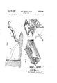
- Fig. l is a longitudinal sectional View of a bullet trap illustrating one embodiment ofthe present invention.
- Fig. 2 is an enlarged sectional view of one form of muzzle blast detiector suitable for use ⁇ with the present invention
- Fig. 3 is a perspective view of one form of bullet collecting basket for use with the embodiment shown;
- Fig. 4 is an enlarged perspective view of one formof trap draining sump suitable for use with the present invention.
- Fig. 5 is a top plan View partially in horizontal section of another embodiment of the present invention wherein the trap includes a resiliently supported inner tank;
- Fig. 6 is a vertical section of the embodiment illustrated in Fig. Staken along a line substantially corresponding to line 6 6 of Fig. 5;
- Fig. 7 is a detail view ot a resilient pad suitable for use in absorbing shock waves.
- Fig. l the invention is shown comprising a horizontally disposed roof wall 11, a base room wall l2 which" may 'slope as illustrated, if desired, and side and end room walls" 13, 14and ⁇ 15.
- a base room wall l2 which" may 'slope as illustrated, if desired, and side and end room walls" 13, 14and ⁇ 15.
- These maybe formed of any suitable material such as concrete; and may if desired be lined with an inner layer 16 or sound insulating or other material.
- a basin 17' to which water or other suitable liquid may be supplied by way of one or more supply pipes 18 terminating just inside the rear vertical wall 19 of the basin; said pipes being in turn supplied with water under pressure ⁇ from any conventional source, not shown.
- the upper and lower walls 21" and 22 of the basin 17 may be parallel to the upper f room wall 11, and at the converging edges of walls 21 and 12 they receive an apertured and pivoted shield 23 adjustably supported by an arm having a turnbuckle ⁇ 24.
- This turnbuckle may include a resilient coupling by the use of springs or rubber bushings.
- a splash shield 27 having sides 26 is mounted as shown.
- the pivoted shield element 23 has an aperture, as at 28, aligning with the aperture 29 in room wall 13; the latterI permitting insertion of the barrel 31 of a gun, orother weapon, adapted to discharge bullets or other missiles into basin 17 by way of aperture 28; the word bullet as used herein being intended to embrace any form of weapon discharged missile. It has been determined that the bullets may be tired into the tank of water at angles from 8 to 20 declination depending upon the shape of the bullet, the angle being necessarily greater for more pointed missiles and less for blunt missiles.
- insulation 20 is shown interposed between the room housing the gun and the room housing the tank.
- a wire mesh basket 36 preferably having the general contour shown in Fig. ⁇ 3, facilitating its reception at the bottorn of the basin, and also its ready withdrawal through the forward opening provided by swinging back the piv otal shield 23, when ⁇ weapon firing has ceased.
- a small drain tank 39 (Fig. 4) from which leads a pipe 41 terminating in a discharge spout 42, in advance of which is a normally closed drain valve 43 operable by turning handwheel 44 disposed at the upper end of the long stem 46. Openings 51 and 52 in the upper concrete wall provide for ventilation and for access and visual inspection and mainpulation of the elements 23 and 44.
- the shield 23 serves generally to deflect to stack 35 the pressures created by gases or comfrom the concerete oor 12 and end Wall 19 by means of suitable springs 41a or other resilient or shock absorbing means whereby the force of the impact of the bullet or bullets upon the body of liquid is absorbed and not transmitted to the adjacent wall.
- a suitable insulating barrier 20 may be interposed between the room containing the tank and the gun test room to isolate the gun from vibrations occurring in the tank room.
- the air supplied through pipes 63 and outlets 64 may be introduced into the tank in a variety of patterns.
- the point of introduction of the bullet into the water indicated generally by the reference character 61, may be surrounded by a curtain of bubbles emerging from a looped conduit 65 embodied in or lying upon the oor of the tank, which bubbles being vcompressible and present in substantial quantity absorb shock caused by bullet entry into the Water.
- a plurality of transversely extending conduits or pipes, perforated as illustrated may be employed to provide a number of curtains of compressible bubbles extending across the tank and through which curtains the shock waves of the bullets must pass.
- an additional transversely extending pipe 66 which in this instance is shown located in the tank outlet sump 39. Bubbles from this pipe provide a protective, absorbent curtain to protect the rear wall from the shock wave.
- the tank walls or a portion thereof both above and below the water line may be lined with a resilient cushion 70 of the general character illustrated in Fig. 7 wherein a so-called unicellular resilient pad is shown.
- This pad may be formed of plastic material having a large number of closely arranged independent cells which are discontinuous and impervious to moisture penetration. Since the cells are not interconnected the pad will not become waterlogged. lt will be apparent that by providing a lining of this material 'within the tank 17 such as along the side or back walls thereof a degree of compressibility is provided to absorb shock waves which strike these surfaces. If desired a perforate mesh screen 71 may be provided over such pads.
- the v shape and disposition of the air emitting muzzles may be 4 is provided a simple and inexpensive means for decelerating and capturing bullets fired from a repeat ing gun and the effect of tiring into the surface of a body of water in the manner illustrated is to individually decelerate each bullet in a burst of bullets, independently of the other bullets in said burst. This occurs because of the action of the water in closing behind a bullet before the succeed- .ing bullet in the burst strikes the surface of the Water, hence even the firing of sustain bursts of bullets do not cause a hole to be bored into the water with consequent striking of the bullets against each other at high velocity.
- a bullet trap comprising a basin containing a liquid to receive a bullet, means including a basket withdrawable from the lowermost rear part of the basin through a top forward part of the basin to recover the bullet after tiring, means supporting a gun adjacent the forward part of the basin at an oblique angle to the surface of the liquid in the basin, and means covering Ia major portion of the basin to control liquid splash.
- a bullet trap comprising an apertured container lled with liquid, an apertured blast deiector pivotally mounted adjacent said container aperture, means for supporting -a firearm for firing into said container at a minimum angle of 8 to the surface of the liquid, a protective shield covering the greater portion of the container, and bullet recovery means including a scoop movably mounted adjacent the bottom of said container.
- a bullet trap comprising a basin containing a liquid to receive a plurality of bullets tired in rapid sequence, mount means adjacent the forward end of the basin, a firearm supported on said mount means at an oblique angle to the horizontal surface of the liquid in the basin, said firearm being positioned to direct the bullet into the basin so that an unimpeded underwater path of substantial length is provided for underwater bullet travel, a blast deector pivotally and adjustably mounted adjacent said basin and having an aperture therein through which the bullet passes prior to entering the liquid, and means forming -a part of said basin and covering a substantial portion thereof for controlling liquid splash upon entrance of the bullet into said liquid.
- a bullet trap for projectiles comprising; a basin containing a liquid and a stand supporting a firearm having a barrel at an oblique angle to the horizontal surface of the liquid in the basin so that the direct line of fire of the projectiles is at an angle to the surface of the liquid in excess of 8, and a blast deilector pivotally and adjustably mounted adjacent said basin and having an aperture Y therein movable in said line of fire of the projectile as the deflector is adjusted with respect to the barrel.
- a bullet trap comprising: a basin containing a liquid to decelerate a bullet, said basin having side Walls, a rear wall, a sloping lower wall and a top wall, said top wall and said lower Wall converging forming a forward opening; a basket placed at the lowermost rear part of the basin and withdrawable through said forward opening to recover a bullet after firing; means supporting a gun adjacent the forward opening of the basin at an oblique angle to the surface of the liquid; and means covering a portion of the basin to control liquid splash.
- a trap for decelerating projectiles fired from an inclined firearm comprising; a container having a quantity of liquid and a projectile entrance opening therein, a blast detlector pivotally and adjustably mounted adjacent said opening and having an aperture therein in alignment with said opening, means supporting a rearm adjacent said opening with the barrel of the firearm at an acute angle with respect to the surface of the liquid and in alignment with said aperture and opening, means forming a part of said container and covering a substantial part of said container for controlling liquid splash yafter the projectile passes through said aperture and opening and upon entrance thereof into said liquid, and supply means arranged within said container and submerged within said liquid for introducing gas into the liquid and render the liquid sufficiently compressible to ⁇ absorb the shock as the projectile enters the liquid and to decelerate the forward progress of the projectile as the projectile travels therethrough.
- a trap for decelerating projectiles red from a rearm comprising a basin containing a quantity of liquid to receive red projectiles, means supporting a firearm to re projectiles into said liquid, means for introducing curtains of gaseous bubbles across the path of underwater travel of the projectiles in a manner to absorb the shock as the projectiles enter the liquid and to decelerate the forward progress of the projectiles as the projectiles travel therethrough, a blast deflector pivotally and adjustably mounted adjacent one end of the basin and having an aperture therein through which the projectiles pass prior to entering the liquid, and means covering a susbtantial portion of the basin to control liquid splash as each projectile strikes and enters the liquid.
- a bullet trap comprising; an apertured container filled with liquid, -an apertured blast dellector pivotally mounted adjacent said container aperture, an enclosure for said container, means within the enclosure for supporting a firearm having a lgun barrel, and an internal wall on said enclosure and provided with an aperture in alignment with and mutually spaced from said deflector aperture and said container aperture, said aperture in the wall having a gun barrel of a rearm disposed therein and extending therethrough for tiring a bullet through said apertured blast deflector into said aperture container at a minimum angle of 8" to the surface of the liquid.
Landscapes
- Engineering & Computer Science (AREA)
- General Engineering & Computer Science (AREA)
- Aiming, Guidance, Guns With A Light Source, Armor, Camouflage, And Targets (AREA)
Description
FIG. s
Nov. 12, 1957 N. D. MARDEN ETAL BULLET TRAP Filed Sept. 15, 1954 5 SheetS-Shee't 1 IMT . INVENTORS NORMAN D. MARDEN ROBERT B. MELAUGHLIN ATTORNEYS Nov. 12, 1957 N. D. MARDEN ETAL 2,812,660
BULLET TRAP Filed sept. 15, 1954 3 Sheets-Sheet 2 INVENT NORMAN D. MARDEN ORS ROBERT B. M2 LAUGHLIN BY 1MM @/iamf ATTORNEYS Nov. 12, 1957 Filed Sept. l5. 1954 N. D. MARDEN ETAL BULLET TRAP 3 Sheets-Sheet 3 FIG.v 6
INVENTORS NORMAN D. MARDEN RT B. MLAUGHLIN ROB aw Q /25 WW ATTORNEYS Sts BULLET TRAP Norman D. Martien, Chincoteague, Va., and Robert lll. McLaughlin, Washington, D. C.
The invention described herein may be manufactured and used by or for the Government of the United States of America for governmental purposes without the payment of any royalties thereon or therefor.
This invention relates to the `trapping of bullets, and more particularly to a method and meansfor dissipating the energy imparted to bullets at the moment of tiring, so that their travel will be confined to a very short distance and will terminate in a specic area where recovery of the spent bullets can be eiected readily and without inconvenience, waste or damage tothe bullets.
Anobject of the invention is to provide a novel method or" decelerating a single bullet, or a burst of several bullets, to prevent bullet travelbeyond a predetermined point.
Another object is to provide a bullet trap of novel construction, having means incorporated therewith to control the course of fired bullets, and to cause them to come to rest in a specified area.
Another object is to provide a bullet trap incorporate ing means facilitating recovery ot spent bullets with a minimum of effort.
In the testing of iirearms it has beencustomary to employ means fortrapping `the bullets discharged by the weapons being tested. Insome instances prior art traps have beenconstructed of bales of straw, sawdust, or banks of sand etc. In other traps a long horizontal conduit has been utilized, the bullets being tired into the conduit simultaneously with the introduction ofa compressible mixture of liquid and gas which is caused by large pumps to ilow in a vortex along thehorizontally placed conduit and thus tend to decelerate the bullet tothevelocity of the tlowin g mixture. t
Each of these Ageneral types of trap has its disadvantages; the sand type being resistant to ready recovery of the' spent bullets, and, when long bursts are attempted, being subject to ricochet and to the creation of clouds of tine dust which are a health` hazard. Liquid traps with a tlowing compressible mixture` are expensive in construction, require largepumps `and are complex instructure, maintenance, and operation. In addition, during the tiring of a sustained burst, the bullets tend to bore `a hole in the liquid thus `destroying its stopping power and causing the bullets to strike each other and to tumble in an uncontrolled manner. Neither form of trap appears to be suitable `for long sustained bursts of tiring.
The present invention provides a newmethod of bullet trapping, by which the travel of the bullet is conined to a veryshort path, and in which deceleration is accomplished without resort to complex mechanism such as is required in the constant flow liquid and air method of trapping abovedescribed At the same time` thetnew method disclosed and claimed herein lends itself to ready recovery of the spentpbullets Without any of the recovery effort involved in thesand bank method of trapping. In additionthe construction of the present Vinvention for the tirstitime 'permits thering oflong bursts of bullets which do not ricochet ott ot eachother and do not bore a' hole arent Al1- 2 in the liquid medium so that it loses its projectile controlling qualities. t
Accordingly, a further object of the invention is to provide a novel and inexpensive method for decelerating and collecting bullets discharged in relatively long bursts, to permit their recovery without any appreciable eiort or damage.
Other objects and many of the attendant advantages of this` invention will be readily appreciated as the same becomes better understood by reference to the following detailed description when considered in connection with the accompanying drawings wherein:
Fig. l is a longitudinal sectional View of a bullet trap illustrating one embodiment ofthe present invention; j
Fig. 2 is an enlarged sectional view of one form of muzzle blast detiector suitable for use` with the present invention;
Fig. 3 is a perspective view of one form of bullet collecting basket for use with the embodiment shown;
Fig. 4 is an enlarged perspective view of one formof trap draining sump suitable for use with the present invention; t
Fig. 5 is a top plan View partially in horizontal section of another embodiment of the present invention wherein the trap includes a resiliently supported inner tank;
Fig. 6 isa vertical section of the embodiment illustrated in Fig. Staken along a line substantially corresponding to line 6 6 of Fig. 5; and
Fig. 7 is a detail view ot a resilient pad suitable for use in absorbing shock waves.
In `the embodimentillustrated in Fig. l the invention is shown comprising a horizontally disposed roof wall 11, a base room wall l2 which" may 'slope as illustrated, if desired, and side and end room walls" 13, 14and` 15. These maybe formed of any suitable material such as concrete; and may if desired be lined with an inner layer 16 or sound insulating or other material. Within `the chamber thus formed there is provided a basin 17' to which water or other suitable liquid may be supplied by way of one or more supply pipes 18 terminating just inside the rear vertical wall 19 of the basin; said pipes being in turn supplied with water under pressure `from any conventional source, not shown. The upper and lower walls 21" and 22 of the basin 17 may be parallel to the upper f room wall 11, and at the converging edges of walls 21 and 12 they receive an apertured and pivoted shield 23 adjustably supported by an arm having a turnbuckle` 24. This turnbuckle may include a resilient coupling by the use of springs or rubber bushings. A splash shield 27 having sides 26 is mounted as shown. The pivoted shield element 23 has an aperture, as at 28, aligning with the aperture 29 in room wall 13; the latterI permitting insertion of the barrel 31 of a gun, orother weapon, adapted to discharge bullets or other missiles into basin 17 by way of aperture 28; the word bullet as used herein being intended to embrace any form of weapon discharged missile. It has been determined that the bullets may be tired into the tank of water at angles from 8 to 20 declination depending upon the shape of the bullet, the angle being necessarily greater for more pointed missiles and less for blunt missiles.
`In fthe embodiment illustrated insulation 20 is shown interposed between the room housing the gun and the room housing the tank.
At thelowermost corner of basin 17 is shown provided a wire mesh basket 36 preferably having the general contour shown in Fig. `3, facilitating its reception at the bottorn of the basin, and also its ready withdrawal through the forward opening provided by swinging back the piv otal shield 23, when` weapon firing has ceased. Belowthe position occupied by the wire mesh basket may be located a small drain tank 39 (Fig. 4) from which leads a pipe 41 terminating in a discharge spout 42, in advance of which is a normally closed drain valve 43 operable by turning handwheel 44 disposed at the upper end of the long stem 46. Openings 51 and 52 in the upper concrete wall provide for ventilation and for access and visual inspection and mainpulation of the elements 23 and 44.
As bullets are discharged from gun barrel 31, either as single shots or as multiple shot bursts, they pass through the aperture in element 23 and strike the surface of the water in basin 17 at the point indicated at 6l, then continue generally down the path indicated generally at 62, the velocity diminishing gradually from point 61, and along path 62, so that sometime before reaching the basket there is no velocity remaining, and they fall to the sloping surface of the bottom. Upon bullet entry into the water some splashing may occur, but shield 27 and the top wall 21 of the basin serve to confine such splashing. It will be noted that the shield 23 serves generally to deflect to stack 35 the pressures created by gases or comfrom the concerete oor 12 and end Wall 19 by means of suitable springs 41a or other resilient or shock absorbing means whereby the force of the impact of the bullet or bullets upon the body of liquid is absorbed and not transmitted to the adjacent wall. As in the first embodiment a suitable insulating barrier 20 may be interposed between the room containing the tank and the gun test room to isolate the gun from vibrations occurring in the tank room.
As illustrated in Fig. 5 the air supplied through pipes 63 and outlets 64 may be introduced into the tank in a variety of patterns. Thus, the point of introduction of the bullet into the water, indicated generally by the reference character 61, may be surrounded by a curtain of bubbles emerging from a looped conduit 65 embodied in or lying upon the oor of the tank, which bubbles being vcompressible and present in substantial quantity absorb shock caused by bullet entry into the Water. Also a plurality of transversely extending conduits or pipes, perforated as illustrated, may be employed to provide a number of curtains of compressible bubbles extending across the tank and through which curtains the shock waves of the bullets must pass. At the far end of the tank and adjacent the rear wall 19 may be provided an additional transversely extending pipe 66 which in this instance is shown located in the tank outlet sump 39. Bubbles from this pipe provide a protective, absorbent curtain to protect the rear wall from the shock wave.
The tank walls or a portion thereof both above and below the water line may be lined with a resilient cushion 70 of the general character illustrated in Fig. 7 wherein a so-called unicellular resilient pad is shown. This pad may be formed of plastic material having a large number of closely arranged independent cells which are discontinuous and impervious to moisture penetration. Since the cells are not interconnected the pad will not become waterlogged. lt will be apparent that by providing a lining of this material 'within the tank 17 such as along the side or back walls thereof a degree of compressibility is provided to absorb shock waves which strike these surfaces. If desired a perforate mesh screen 71 may be provided over such pads.
It will be apparent to those skilled in the art that the v shape and disposition of the air emitting muzzles may be 4 is provided a simple and inexpensive means for decelerating and capturing bullets fired from a repeat ing gun and the effect of tiring into the surface of a body of water in the manner illustrated is to individually decelerate each bullet in a burst of bullets, independently of the other bullets in said burst. This occurs because of the action of the water in closing behind a bullet before the succeed- .ing bullet in the burst strikes the surface of the Water, hence even the firing of sustain bursts of bullets do not cause a hole to be bored into the water with consequent striking of the bullets against each other at high velocity.
Obviously many modifications and variations off the present invention are possible in the light of the above teachings. It is therefore to be understood that within the scope of the appended claims the invention may be practiced otherwise than as specifically described.
What is claimed is:
l. A bullet trap comprising a basin containing a liquid to receive a bullet, means including a basket withdrawable from the lowermost rear part of the basin through a top forward part of the basin to recover the bullet after tiring, means supporting a gun adjacent the forward part of the basin at an oblique angle to the surface of the liquid in the basin, and means covering Ia major portion of the basin to control liquid splash.
2. A bullet trap comprising an apertured container lled with liquid, an apertured blast deiector pivotally mounted adjacent said container aperture, means for supporting -a firearm for firing into said container at a minimum angle of 8 to the surface of the liquid, a protective shield covering the greater portion of the container, and bullet recovery means including a scoop movably mounted adjacent the bottom of said container.
3. A bullet trap comprising a basin containing a liquid to receive a plurality of bullets tired in rapid sequence, mount means adjacent the forward end of the basin, a firearm supported on said mount means at an oblique angle to the horizontal surface of the liquid in the basin, said firearm being positioned to direct the bullet into the basin so that an unimpeded underwater path of substantial length is provided for underwater bullet travel, a blast deector pivotally and adjustably mounted adjacent said basin and having an aperture therein through which the bullet passes prior to entering the liquid, and means forming -a part of said basin and covering a substantial portion thereof for controlling liquid splash upon entrance of the bullet into said liquid.
4. A bullet trap for projectiles comprising; a basin containing a liquid and a stand supporting a firearm having a barrel at an oblique angle to the horizontal surface of the liquid in the basin so that the direct line of fire of the projectiles is at an angle to the surface of the liquid in excess of 8, and a blast deilector pivotally and adjustably mounted adjacent said basin and having an aperture Y therein movable in said line of fire of the projectile as the deflector is adjusted with respect to the barrel.
5. A bullet trap comprising: a basin containing a liquid to decelerate a bullet, said basin having side Walls, a rear wall, a sloping lower wall and a top wall, said top wall and said lower Wall converging forming a forward opening; a basket placed at the lowermost rear part of the basin and withdrawable through said forward opening to recover a bullet after firing; means supporting a gun adjacent the forward opening of the basin at an oblique angle to the surface of the liquid; and means covering a portion of the basin to control liquid splash.
6. A bullet trap as set forth in claim 5, said Walls being lined with a cushion of resilient, plastic material of closely arranged independent cells impervious to moisture penetration so that any shock waves, caused by a bullet, are absorbed upon striking the cushion.
7. A trap for decelerating projectiles fired from an inclined firearm comprising; a container having a quantity of liquid and a projectile entrance opening therein, a blast detlector pivotally and adjustably mounted adjacent said opening and having an aperture therein in alignment with said opening, means supporting a rearm adjacent said opening with the barrel of the lirearm at an acute angle with respect to the surface of the liquid and in alignment with said aperture and opening, means forming a part of said container and covering a substantial part of said container for controlling liquid splash yafter the projectile passes through said aperture and opening and upon entrance thereof into said liquid, and supply means arranged within said container and submerged within said liquid for introducing gas into the liquid and render the liquid sufficiently compressible to `absorb the shock as the projectile enters the liquid and to decelerate the forward progress of the projectile as the projectile travels therethrough.
8. A trap for decelerating projectiles red from a rearm comprising a basin containing a quantity of liquid to receive red projectiles, means supporting a firearm to re projectiles into said liquid, means for introducing curtains of gaseous bubbles across the path of underwater travel of the projectiles in a manner to absorb the shock as the projectiles enter the liquid and to decelerate the forward progress of the projectiles as the projectiles travel therethrough, a blast deflector pivotally and adjustably mounted adjacent one end of the basin and having an aperture therein through which the projectiles pass prior to entering the liquid, and means covering a susbtantial portion of the basin to control liquid splash as each projectile strikes and enters the liquid.
9. A bullet trap comprising; an apertured container filled with liquid, -an apertured blast dellector pivotally mounted adjacent said container aperture, an enclosure for said container, means within the enclosure for supporting a firearm having a lgun barrel, and an internal wall on said enclosure and provided with an aperture in alignment with and mutually spaced from said deflector aperture and said container aperture, said aperture in the wall having a gun barrel of a rearm disposed therein and extending therethrough for tiring a bullet through said apertured blast deflector into said aperture container at a minimum angle of 8" to the surface of the liquid.
References Cited in the le of this patent UNITED STATES PATENTS 2,420,304 Diem May 13, 1947 2,422,284 Andresen June 17, 1947 2,487,042 Christie Nov. 8, 1949 2,525,843 Walker Oct. 17, 1950
Priority Applications (1)
| Application Number | Priority Date | Filing Date | Title |
|---|---|---|---|
| US456341A US2812660A (en) | 1954-09-15 | 1954-09-15 | Bullet trap |
Applications Claiming Priority (1)
| Application Number | Priority Date | Filing Date | Title |
|---|---|---|---|
| US456341A US2812660A (en) | 1954-09-15 | 1954-09-15 | Bullet trap |
Publications (1)
| Publication Number | Publication Date |
|---|---|
| US2812660A true US2812660A (en) | 1957-11-12 |
Family
ID=23812362
Family Applications (1)
| Application Number | Title | Priority Date | Filing Date |
|---|---|---|---|
| US456341A Expired - Lifetime US2812660A (en) | 1954-09-15 | 1954-09-15 | Bullet trap |
Country Status (1)
| Country | Link |
|---|---|
| US (1) | US2812660A (en) |
Cited By (19)
| Publication number | Priority date | Publication date | Assignee | Title |
|---|---|---|---|---|
| DE1273374B (en) * | 1965-06-05 | 1968-07-18 | Kloeckner Werke Ag | Bullet trap chamber |
| US4201385A (en) * | 1976-10-25 | 1980-05-06 | Andreas Szabados | Sound insulated target apparatus with projectile butt container |
| US4418786A (en) * | 1980-09-18 | 1983-12-06 | Mapco, Inc. | Bottom diaphragm for transporter for a seismic energy source |
| US4509301A (en) * | 1982-04-23 | 1985-04-09 | Head Robert L | Modular shooting range |
| US4683688A (en) * | 1984-03-16 | 1987-08-04 | Wojcinski Allan S | Containerized shooting range |
| US4775120A (en) * | 1980-04-07 | 1988-10-04 | Marwick Edward F | Extraterrestrial transportation apparatus and method |
| US4787289A (en) * | 1988-01-15 | 1988-11-29 | Duer Morris J | Bullet trap |
| US5199671A (en) * | 1975-01-27 | 1993-04-06 | Marwick Edward F | Extraterrestrial transportation apparatus and methods |
| US5357796A (en) * | 1993-10-01 | 1994-10-25 | Jamison John R | Ballistics measuring system |
| US5531113A (en) * | 1993-10-01 | 1996-07-02 | Jamison; John R. | Ballistics measuring system |
| US5718434A (en) * | 1995-04-10 | 1998-02-17 | Wilderness Expeditions, Inc. | Bullet trap |
| WO2004076958A3 (en) * | 2003-02-28 | 2005-02-03 | Allan Stefan Wojcinski | Device for charging, discharging, and trying out and adjusting guns, and protective cabin for said device |
| US20080258396A1 (en) * | 2005-05-04 | 2008-10-23 | Andrey Albertovich Polovnev | Aqua Shooting Range |
| DE102009006106A1 (en) | 2009-01-26 | 2010-07-29 | Rheinmetall Waffe Munition Gmbh | Safety catch for destructionless deceleration of projectile, has container that is filled with liquid i.e. water, and gas i.e. air, where gas is precompressed via liquid during movement of projectile via liquid |
| CN104121825A (en) * | 2014-07-24 | 2014-10-29 | 中北大学 | Speed reducing device for retrieving high-speed flight body with slight damage |
| RU2584183C1 (en) * | 2014-10-28 | 2016-05-20 | Российская Федерация, от имени которой выступает Министерство промышленности и торговли Российской Федерации (Минпромторг РФ) | Catcher for models of missiles |
| IT202100001835A1 (en) * | 2021-01-29 | 2022-07-29 | Leonardo Spa | SYSTEM FOR BRAKING AND RECOVERY OF BULLETS EQUIPPED WITH A COLLECTOR ASSEMBLY. |
| IT202100001844A1 (en) * | 2021-01-29 | 2022-07-29 | Leonardo Spa | SYSTEM FOR BRAKING AND RECOVERY OF BULLETS EQUIPPED WITH COVER PANEL. |
| IT202100001820A1 (en) * | 2021-01-29 | 2022-07-29 | Leonardo Spa | SYSTEM FOR BRAKING AND RECOVERY OF BULLETS EQUIPPED WITH A COUNTER-BAD ASSEMBLY. |
Citations (4)
| Publication number | Priority date | Publication date | Assignee | Title |
|---|---|---|---|---|
| US2420304A (en) * | 1944-05-05 | 1947-05-13 | Donald T Diem | Spent bullet trap |
| US2422284A (en) * | 1944-05-17 | 1947-06-17 | Remington Arms Co Inc | Bullet trap |
| US2487042A (en) * | 1948-10-14 | 1949-11-08 | William H Christie | Variable angle launcher |
| US2525843A (en) * | 1945-03-16 | 1950-10-17 | Walker Brooks | Bullet trap |
-
1954
- 1954-09-15 US US456341A patent/US2812660A/en not_active Expired - Lifetime
Patent Citations (4)
| Publication number | Priority date | Publication date | Assignee | Title |
|---|---|---|---|---|
| US2420304A (en) * | 1944-05-05 | 1947-05-13 | Donald T Diem | Spent bullet trap |
| US2422284A (en) * | 1944-05-17 | 1947-06-17 | Remington Arms Co Inc | Bullet trap |
| US2525843A (en) * | 1945-03-16 | 1950-10-17 | Walker Brooks | Bullet trap |
| US2487042A (en) * | 1948-10-14 | 1949-11-08 | William H Christie | Variable angle launcher |
Cited By (25)
| Publication number | Priority date | Publication date | Assignee | Title |
|---|---|---|---|---|
| DE1273374B (en) * | 1965-06-05 | 1968-07-18 | Kloeckner Werke Ag | Bullet trap chamber |
| US3447806A (en) * | 1965-06-05 | 1969-06-03 | Kloeckner Werke Ag | Bullet trapping assembly |
| US5199671A (en) * | 1975-01-27 | 1993-04-06 | Marwick Edward F | Extraterrestrial transportation apparatus and methods |
| US4201385A (en) * | 1976-10-25 | 1980-05-06 | Andreas Szabados | Sound insulated target apparatus with projectile butt container |
| US4775120A (en) * | 1980-04-07 | 1988-10-04 | Marwick Edward F | Extraterrestrial transportation apparatus and method |
| US4418786A (en) * | 1980-09-18 | 1983-12-06 | Mapco, Inc. | Bottom diaphragm for transporter for a seismic energy source |
| US4509301A (en) * | 1982-04-23 | 1985-04-09 | Head Robert L | Modular shooting range |
| US4683688A (en) * | 1984-03-16 | 1987-08-04 | Wojcinski Allan S | Containerized shooting range |
| US4787289A (en) * | 1988-01-15 | 1988-11-29 | Duer Morris J | Bullet trap |
| US5357796A (en) * | 1993-10-01 | 1994-10-25 | Jamison John R | Ballistics measuring system |
| US5531113A (en) * | 1993-10-01 | 1996-07-02 | Jamison; John R. | Ballistics measuring system |
| US5718434A (en) * | 1995-04-10 | 1998-02-17 | Wilderness Expeditions, Inc. | Bullet trap |
| WO2004076958A3 (en) * | 2003-02-28 | 2005-02-03 | Allan Stefan Wojcinski | Device for charging, discharging, and trying out and adjusting guns, and protective cabin for said device |
| US20080258396A1 (en) * | 2005-05-04 | 2008-10-23 | Andrey Albertovich Polovnev | Aqua Shooting Range |
| US7942420B2 (en) * | 2005-05-04 | 2011-05-17 | Dsg Technology As | Aqua shooting range |
| DE102009006106A1 (en) | 2009-01-26 | 2010-07-29 | Rheinmetall Waffe Munition Gmbh | Safety catch for destructionless deceleration of projectile, has container that is filled with liquid i.e. water, and gas i.e. air, where gas is precompressed via liquid during movement of projectile via liquid |
| CN104121825A (en) * | 2014-07-24 | 2014-10-29 | 中北大学 | Speed reducing device for retrieving high-speed flight body with slight damage |
| CN104121825B (en) * | 2014-07-24 | 2016-02-24 | 中北大学 | Micro-damage reclaims the deceleration device of high-speed flying orbit |
| RU2584183C1 (en) * | 2014-10-28 | 2016-05-20 | Российская Федерация, от имени которой выступает Министерство промышленности и торговли Российской Федерации (Минпромторг РФ) | Catcher for models of missiles |
| IT202100001835A1 (en) * | 2021-01-29 | 2022-07-29 | Leonardo Spa | SYSTEM FOR BRAKING AND RECOVERY OF BULLETS EQUIPPED WITH A COLLECTOR ASSEMBLY. |
| IT202100001844A1 (en) * | 2021-01-29 | 2022-07-29 | Leonardo Spa | SYSTEM FOR BRAKING AND RECOVERY OF BULLETS EQUIPPED WITH COVER PANEL. |
| IT202100001820A1 (en) * | 2021-01-29 | 2022-07-29 | Leonardo Spa | SYSTEM FOR BRAKING AND RECOVERY OF BULLETS EQUIPPED WITH A COUNTER-BAD ASSEMBLY. |
| WO2022162577A1 (en) * | 2021-01-29 | 2022-08-04 | Leonardo Spa | System for braking and recovering projectiles, provided with a covering panel |
| WO2022162574A1 (en) * | 2021-01-29 | 2022-08-04 | Leonardo S.P.A. | System for braking and recovering projectiles, provided with a collecting assembly |
| WO2022162573A1 (en) * | 2021-01-29 | 2022-08-04 | Leonardo S.P.A. | System for braking and recovering projectiles, provided with a counter barrel assembly |
Similar Documents
| Publication | Publication Date | Title |
|---|---|---|
| US2812660A (en) | Bullet trap | |
| KR101644918B1 (en) | Bullet head recovery system at indoor shooting ranges for firing with live ammunition, for preventing the occurrence of the lead fume | |
| TW208740B (en) | ||
| US5486008A (en) | Bullet trap | |
| US4286708A (en) | Module to prevent sympathetic detonations in munitions | |
| US5113700A (en) | Bullet trap | |
| US2631454A (en) | Water gun butt and apparatus | |
| GB1078590A (en) | Projectile-trapping chamber | |
| IL97417A (en) | Warhead such as a torpedo | |
| US4961393A (en) | Anti-projectile protection fence and method for marine surface vessels | |
| US3495532A (en) | Antitank land mine | |
| US20130125656A1 (en) | Method And Apparatus For Shockwave Attenuation | |
| US3186304A (en) | Hypervelocity gun | |
| CN106197141A (en) | The water-proof air-inflated protection device of firearms transmitting tube and method under water | |
| US6446974B1 (en) | Durable system for controlling the disposition of expended munitions fired at a target positioned close to the shooter | |
| Homae et al. | Reduction of explosion damage using sand or water layer | |
| AU645163B2 (en) | Bullet trap | |
| JP3806878B2 (en) | Shooting training ground and stopping device | |
| US2459156A (en) | Gun test range | |
| US1294407A (en) | Water butt. | |
| RU2081466C1 (en) | Method for confinement of gas-aerosol ejection | |
| CN211855051U (en) | Portable gun tester | |
| KR102590590B1 (en) | Testing device for torpedo launching | |
| RU2235964C1 (en) | Bullet catcher | |
| KR101492715B1 (en) | Bullet head collecting apparatus for real distance shooting range |