US2812640A - hartley etal - Google Patents
hartley etal Download PDFInfo
- Publication number
- US2812640A US2812640A US2812640DA US2812640A US 2812640 A US2812640 A US 2812640A US 2812640D A US2812640D A US 2812640DA US 2812640 A US2812640 A US 2812640A
- Authority
- US
- United States
- Prior art keywords
- cable
- trough
- stern
- ship
- sheave
- Prior art date
- Legal status (The legal status is an assumption and is not a legal conclusion. Google has not performed a legal analysis and makes no representation as to the accuracy of the status listed.)
- Expired - Lifetime
Links
- 239000007787 solid Substances 0.000 description 7
- 238000005192 partition Methods 0.000 description 4
- 238000005452 bending Methods 0.000 description 2
- 230000005540 biological transmission Effects 0.000 description 1
- 230000000694 effects Effects 0.000 description 1
- 230000005484 gravity Effects 0.000 description 1
- 238000000034 method Methods 0.000 description 1
- 230000000630 rising effect Effects 0.000 description 1
- 238000004804 winding Methods 0.000 description 1
Images
Classifications
-
- B—PERFORMING OPERATIONS; TRANSPORTING
- B63—SHIPS OR OTHER WATERBORNE VESSELS; RELATED EQUIPMENT
- B63B—SHIPS OR OTHER WATERBORNE VESSELS; EQUIPMENT FOR SHIPPING
- B63B35/00—Vessels or similar floating structures specially adapted for specific purposes and not otherwise provided for
- B63B35/04—Cable-laying vessels
Definitions
- This invention relates to apparatus for laying submarine cables, and, more particularly, submarine cables in which repeaters are connected at intervals of say 50 miles.
- the object of the invention is the provision of improvements in such apparatus and particularly in the launching mechanism by which the repeaters are passed over the stern of the ship into the sea.
- the invention consists broadly of an apparatus for guiding a submarine cable from a cable-laying ship into the sea, said cable having a solid object such as a repeater connected in its line, comprising main and auxiliary pulleys having a normal correlation such that the cable passes above the auxiliary pulley, without bending round it, and then bends round the main pulley into the sea, and means whereby, when said object has passed said auxiliary pulley but not said main pulley, the pull of the cable itself effects relative movement of said pulleys to a launching correlation such that said main pulley occupies a position beneath said auxiliary pulley and said cable bends round said auxiliary pulley into the sea without bending round said main pulley.
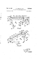
- Figure l is a side elevationof said launching mechanism at the normal position at which it forms a guide for the cable being payed out over the stern of the ship;
- Figure 2 is a similar View of the same at an intermediate launching position, at which it is in process of launching a repeater connected in the line of cable;
- Figure 3 is a similar view of the same at its final launching position at which it has launched the repeater, which is between the ship and the sea.
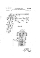
- Figure 4 is an end elevation to a larger scale, looking from the left of Figure 1, of the upper portion of the launching mechanism.
- the trough 2 which is of U-section as shown, is permanently mounted on a longitudinal support beneath it, which support is constituted by two parallel elongated side plates 10 in vertical planes, said plates being connected at their upper edges by means of horizontal cross pieces 11 which form supports for the two ends of the trough and to which said trough is fixedly secured.
- These two plates iii extend aft beyond the aft end of the trough 2 and their extending portions are pivoted to the spindle 12 of said stern sheave 9, one each side of said stern sheave.
- the ship has a longitudinal vertical slot 13 cut into it from the stern end, and the trough 2 is normally located immediately above said slot.
- the plates 10 at their forward ends have respective feet 14 extending outwardly from them, and these feet normally rest on the deck one each side of the slot 13 and thereby support the rear end of said plates.
- the spindle 12 of the stern sheave constitutes a pin which pin joints two links 15 and 16, each of which consists of two parallel plates pivoted to said spindle 12 one each side thereof as, shown. in Figure 4.
- the link 15, hereinafter called the afterlink normally extends downwardly and forwardly from said stern sheave 9, into said slot 13, and is pivoted at its lower end to the ship by means of a pivot pin 17.
- the other link 16 hereinafter called the connecting link, normally extends forwardly and at a very slight angle downwardly into said slot 13, and, at its forward end is pin-jointed by means of a pivot pin 18, to one end of a third link 19, hereinafter called the forward link which normally extends downwardly and rearwardly within said slot 13 and has its lower end pivoted to the ship by means of a pivot pin 20.
- said connecting link 16 is normally within the slot 13 just beneath the trough 2. Its forward end is to the fore of the forward end of said trough.
- the pin 18 which joints the connecting link 16 to the forward link 19 forms the spindle of a second sheave or pulley 21, hereinafter called the auxiliary sheave or pulley. This normally lies within the slot 1.3with the uppermost portion of its periphery just above deck level as shown in Figure 1.
- the trough 2 moves aftwards with its rear feet 14 sliding along the ships deck, but after a short movement the connecting link 16, whose rear end is rising as Well as moving aftwards, engages said feet 14 and picks the trough 2 up, and thereafter said trough moves entirely with said connecting link. Finally therefore, as shown in Figure 3, said trough 2 reaches a position at which it is tilted nearly to the vertical and is held outboard from the stern 4 or" the ship at a level wholly beneath deck level.
- the cable 3 can now continue to be payed out, passing over the auxiliary sheave 21, but, at some time before the next repeater arrives, the Whole launching gear must be returned to the normal position, preparatory to another aftwards movement for launching said next repeater.
- This return to the normal position must be effected by power, and, in order to obtain the maximum resultant thrust of the cable on the sheaves is best efiected while the after winch is being restored to the operative position and the cable runs at an angle downwards therefrom to the stern of the ship.
- the return of the launching gear to the normal position is effected by means of a prime mover 22. mounted on one side of the slot 13 with its spindle 23 extending into said slot and having a winding drum 24 mounted on it in said slot.
- a hawser 25, which is coiled on said drum, has its end secured to a cross rod 26 which extends between the two plates forming the forward link 19. By rotation of the drum 24 the hawser 2,5 is wound thereon and said link 19, and
- a high ratio stepdown transmission gearing is provided between said prime mover 22 and said spindle 23.
- Stops 27 and 28 are provided to engage the forward link 19 and thereby limit the linkage at both its normal and its launching positions. Gravity maintains said linkage against said stops at both positions.
- the two plates which support the trough 2 have downward extensions at their rear ends from which respective lugs 29 project outwards vertically beneath the feet 14, and at a level beneath the two plates forming the connecting link 16.
- the purpose of these lugs 29 is to ensure against the trough 2 ever falling right away from the connecting link 16, say by inertia, during movement to the launching position.
- the connecting link 16 has mounted on it, immediately to the fore of the forward end of the trough 2, a transverse partition 30. Normally the upper edge of this partition is just about level with the bottom of the trough 2, but, as said connecting link 16 rises to pick up said trough, said partition 30 rises relative to said trough, and, during the movement into the launching position constitutes a closure for the forward end of the trough.
- This partition like the closure 6 at the aft end of the trough, has a notch in it to accommodate the cable.
- the slot in the ship is lined at its sides with plates 31 to carry the pivot pins 17 and 20 and the stops 27 and 25, which latter consist of transverse rods extending between said plates 31.
- These plates 31 also serve to prevent any possibility of the linkage buckling.
- one of said supporting links is pivoted to said connecting link adjacent the main pulley so that, in moving to the second position ofthe pulleys, said main pulley moves on a path mainly downward, and the other supporting link is pivoted to said connecting link adjacent to the auxiliary pulley so that, in moving to said second position said auxiliary pulley moves upward toward the cable.
Landscapes
- Chemical & Material Sciences (AREA)
- Engineering & Computer Science (AREA)
- Combustion & Propulsion (AREA)
- Mechanical Engineering (AREA)
- Ocean & Marine Engineering (AREA)
- Laying Of Electric Cables Or Lines Outside (AREA)
Description
Nov- 9 A. c. HARTLEY ETAL 1 2,
APPARATUS FOR LAYING' SUBMARINE CABLES Filed July 2,1954 V 2 Sheets-Shea; 1
haven-r025 14.6. HamlZc y q-hd R.J. ASflb y um-M Nov. 12, 1957 A. c. HARTLEY ET AL 2,812,640
APPARATUS FOR LAYING SUBMARINE CABLES 2 Sheets-Sheet 2 Filed July 2, 1954 4 w. M 5y w mf .A 2& WHAJW l R U m 2,812,640 Patented Nov. 12, 1957 APPARATUS FOR LAYING SUBMARINE CABLES Arthur Clifford Hartley, West Byfleet, and Ronald Joseph Ashby, .Orpington, England, assignors to Johnson & Phiilips Limited, London, England Application July 2, 1954, Serial No. 440,962
Claims priority, application Great Britain July 6, 1953 4 Claims. (CI. 61-72) This invention relates to apparatus for laying submarine cables, and, more particularly, submarine cables in which repeaters are connected at intervals of say 50 miles.
The object of the invention is the provision of improvements in such apparatus and particularly in the launching mechanism by which the repeaters are passed over the stern of the ship into the sea.
The invention consists broadly of an apparatus for guiding a submarine cable from a cable-laying ship into the sea, said cable having a solid object such as a repeater connected in its line, comprising main and auxiliary pulleys having a normal correlation such that the cable passes above the auxiliary pulley, without bending round it, and then bends round the main pulley into the sea, and means whereby, when said object has passed said auxiliary pulley but not said main pulley, the pull of the cable itself effects relative movement of said pulleys to a launching correlation such that said main pulley occupies a position beneath said auxiliary pulley and said cable bends round said auxiliary pulley into the sea without bending round said main pulley.
In order that the invention may be the more clearly understood a launching mechanism in accordance there with will now be described, reference being made to the accompanying drawings wherein:
Figure l is a side elevationof said launching mechanism at the normal position at which it forms a guide for the cable being payed out over the stern of the ship;
Figure 2 is a similar View of the same at an intermediate launching position, at which it is in process of launching a repeater connected in the line of cable;
Figure 3 is a similar view of the same at its final launching position at which it has launched the repeater, which is between the ship and the sea.
Figure 4 is an end elevation to a larger scale, looking from the left of Figure 1, of the upper portion of the launching mechanism.
The whole system in which the launching mechanism is incorporated is as described in our copending application Serial No. 427,502, filed May 4, 1954, now Patent No. 2,756,873, except that the launching mechanism itself is different. In the present arrangement the tubular track described in said application continues aft beyond the after winch, but does not extend, as in said application, over the stern of the ship. instead, it terminates, as indicated at 1 (Figures 1 and 3), close to the forward end of a trough 2, which is normally in line with it just above the level of the deck 3, and whose after end is normally just outboard over the stern i of the ship. This trough 2 is of a size to comfortably receive a repeater 5 (Figures 2 and 3). Its forward end is open, and its after end is closed at 6, but the closure of said after end is formed with a notch 7 which allows the cable 8 to pass freely through it. Immediately to the aft of the after end of said trough 2 there is normally a stern sheave or pulley 9, and normally, i. e. during the paying out of the 50 miles or so of cable 8 between repeaters 5, the cable passes from the after winch to said stern sheave 9 over which it passes direct into the sea.
When a repeater 5 arrives it passes through the two winches in succession, as described in said aforesaid application, and then continues along the track 1, and, from the after end of said track, it slides into the trough 2 until it abuts against the closure 6 at the after end of said trough. During this time the cable willhave been passing along the trough, and, through the slot 7 in the closure 6, to the stern sheave 9.
The trough 2, which is of U-section as shown, is permanently mounted on a longitudinal support beneath it, which support is constituted by two parallel elongated side plates 10 in vertical planes, said plates being connected at their upper edges by means of horizontal cross pieces 11 which form supports for the two ends of the trough and to which said trough is fixedly secured. These two plates iii extend aft beyond the aft end of the trough 2 and their extending portions are pivoted to the spindle 12 of said stern sheave 9, one each side of said stern sheave. The ship has a longitudinal vertical slot 13 cut into it from the stern end, and the trough 2 is normally located immediately above said slot. The plates 10 at their forward ends have respective feet 14 extending outwardly from them, and these feet normally rest on the deck one each side of the slot 13 and thereby support the rear end of said plates.
The spindle 12 of the stern sheave constitutes a pin which pin joints two links 15 and 16, each of which consists of two parallel plates pivoted to said spindle 12 one each side thereof as, shown. in Figure 4. The link 15, hereinafter called the afterlink, normally extends downwardly and forwardly from said stern sheave 9, into said slot 13, and is pivoted at its lower end to the ship by means of a pivot pin 17. The other link 16, hereinafter called the connecting link, normally extends forwardly and at a very slight angle downwardly into said slot 13, and, at its forward end is pin-jointed by means of a pivot pin 18, to one end of a third link 19, hereinafter called the forward link which normally extends downwardly and rearwardly within said slot 13 and has its lower end pivoted to the ship by means of a pivot pin 20.
Thus, said connecting link 16 is normally within the slot 13 just beneath the trough 2. Its forward end is to the fore of the forward end of said trough. The pin 18 which joints the connecting link 16 to the forward link 19 forms the spindle of a second sheave or pulley 21, hereinafter called the auxiliary sheave or pulley. This normally lies within the slot 1.3with the uppermost portion of its periphery just above deck level as shown in Figure 1.
When the repeater 5 abuts against the closure 6 at the after end of the trough 2 as heretofore described, continued paying out of the cable it forces said trough 2 afterwards, and therefore, owing to the pivot connection of said trough to the spindle 12 of the stern sheave 9, forces the whole linkage aftwards through the position of Figure 2 to the position of Figure 3. That is to say the aft link 15 swings downwards until the stern sheave 9 occupies a position about vertically beneath its normal position, and the forward link 19 swings aftwards until. the auxiliary sheave 21 occupies a position just forwardly of the normal position of said stern sheave 9. The connecting link 16 therefore is tilted nearly to the vertical position with its major portion outboard from the stern of the ship.
During the first portion of this movement of the linkage, the trough 2 moves aftwards with its rear feet 14 sliding along the ships deck, but after a short movement the connecting link 16, whose rear end is rising as Well as moving aftwards, engages said feet 14 and picks the trough 2 up, and thereafter said trough moves entirely with said connecting link. Finally therefore, as shown in Figure 3, said trough 2 reaches a position at which it is tilted nearly to the vertical and is held outboard from the stern 4 or" the ship at a level wholly beneath deck level.
During this aftwards movement of the auxiliary sheave, which rises somewhat, as well as moving aftwards, picks up the cable 3 which thereafter runs over it, and at some point during the simultaneous downward movement of the stern sheave 9 and the trough 2, said stern sheave departs from the cable, leaving the same at its normal angle from the auxiliary sheave 21 to the sea, and said trough 2 likewise departs from the repeater 5, leaving it supported solely by the cable 8 as shown in Figure 3, until it passes with the cable into the sea.
The cable 3 can now continue to be payed out, passing over the auxiliary sheave 21, but, at some time before the next repeater arrives, the Whole launching gear must be returned to the normal position, preparatory to another aftwards movement for launching said next repeater. This return to the normal position must be effected by power, and, in order to obtain the maximum resultant thrust of the cable on the sheaves is best efiected while the after winch is being restored to the operative position and the cable runs at an angle downwards therefrom to the stern of the ship.
In the arrangement illustrated the return of the launching gear to the normal position is effected by means of a prime mover 22. mounted on one side of the slot 13 with its spindle 23 extending into said slot and having a winding drum 24 mounted on it in said slot. A hawser 25, which is coiled on said drum, has its end secured to a cross rod 26 which extends between the two plates forming the forward link 19. By rotation of the drum 24 the hawser 2,5 is wound thereon and said link 19, and
. therefore the whole launching, is pulled back to the normal position illustrated in Figure 1. A high ratio stepdown transmission gearing is provided between said prime mover 22 and said spindle 23.
Describing now some of the constructional details, the two plates which support the trough 2 have downward extensions at their rear ends from which respective lugs 29 project outwards vertically beneath the feet 14, and at a level beneath the two plates forming the connecting link 16. The purpose of these lugs 29 is to ensure against the trough 2 ever falling right away from the connecting link 16, say by inertia, during movement to the launching position.
The connecting link 16 has mounted on it, immediately to the fore of the forward end of the trough 2, a transverse partition 30. Normally the upper edge of this partition is just about level with the bottom of the trough 2, but, as said connecting link 16 rises to pick up said trough, said partition 30 rises relative to said trough, and, during the movement into the launching position constitutes a closure for the forward end of the trough. This partition, like the closure 6 at the aft end of the trough, has a notch in it to accommodate the cable.
The slot in the ship is lined at its sides with plates 31 to carry the pivot pins 17 and 20 and the stops 27 and 25, which latter consist of transverse rods extending between said plates 31. These plates 31 also serve to prevent any possibility of the linkage buckling.
Obviously the launching mechanism described can be employed with other forms of paying-out mechanism, such as that described in copending application Serial No. 331,035, filed January 13, 1953, in the name of George Thomas William Whitehead, now abandoned, cognate with copending application Serial No. 346,903, filed April 6, 1953, in the name of David Graham, now Patent No. 2,792,930.
We claim:
1. An apparatus for guiding a submarine cable from a cable-laying ship into the sea, said cable having solid object such as a repeater connected in its line, said apparatus comprising main and auxiliary pulleys rotating on horizontal axes, each being mounted on a supporting link pivotally mounted in spaced relation on the ship for adjustment to two guiding positions, in the first position the auxiliary pulley being below and out of the path of travel of the cable and out of the path of travel of the solid object, said main pulley guiding the cable into the sea, and in the second position the main pulley being out of the path of travel of the cable and the auxiliary pulley guiding the cable into the sea; linkage means pivotally connected between the spaced pulleys and movable as a unit with said pulleys, guide means on said linkage means for receiving and guiding the solid object between the pulleys in the first position thereof, said guide means having a member for obstructing the travel of the solid object toward the main pulley in the first position of the pulleys; said solid object engaging said obstructing member and by continued travel of the cable being moved with the linkage means and the pulleys into the second position and said movement of the pulleys into the second position moving the obstructing member out of the path of travel of the solid object and moving said auxiliary pulley into guiding engagement with the cable.
2. An apparatus according to claim 1, wherein one of said supporting links is pivoted to said connecting link adjacent the main pulley so that, in moving to the second position ofthe pulleys, said main pulley moves on a path mainly downward, and the other supporting link is pivoted to said connecting link adjacent to the auxiliary pulley so that, in moving to said second position said auxiliary pulley moves upward toward the cable.
3. An apparatus according to claim 1, a prime mover connected to one of said supporting links to return the References Cited in the file of this patent UNITED STATES PATENTS 1,703,777 Pernot Feb. 26, 1929 2,756,873 Hartley et a1. July 31, 1956 FOREIGN PATENTS 355,002 Great Britain Aug. 20, 1931
Publications (1)
| Publication Number | Publication Date |
|---|---|
| US2812640A true US2812640A (en) | 1957-11-12 |
Family
ID=3446744
Family Applications (1)
| Application Number | Title | Priority Date | Filing Date |
|---|---|---|---|
| US2812640D Expired - Lifetime US2812640A (en) | hartley etal |
Country Status (1)
| Country | Link |
|---|---|
| US (1) | US2812640A (en) |
Cited By (6)
| Publication number | Priority date | Publication date | Assignee | Title |
|---|---|---|---|---|
| US2931185A (en) * | 1960-04-05 | Apparatus for use in laying submarine cables | ||
| US4465253A (en) * | 1983-04-19 | 1984-08-14 | The United States Of America As Represented By The Secretary Of The Air Force | Flexible line support assembly |
| US4465242A (en) * | 1980-10-31 | 1984-08-14 | Rieter Machine Works Ltd. | Method and apparatus for inserting threads and similar items into a winding device |
| US9527702B2 (en) * | 2013-04-30 | 2016-12-27 | Next Hydraulics S.R.L. | Hoist pull-limiting device |
| WO2018217085A1 (en) | 2017-05-22 | 2018-11-29 | Ece Offshore B.V. | Deployment method to deploy a cable from a vessel |
| EP3573888A1 (en) * | 2017-01-26 | 2019-12-04 | Ecosse Subsea Systems Limited | Method and apparatus for laying subsea cable from on-board a vessel |
Citations (3)
| Publication number | Priority date | Publication date | Assignee | Title |
|---|---|---|---|---|
| GB355002A (en) * | ||||
| US1703777A (en) * | 1922-02-03 | 1929-02-26 | Pernot Frederick Eugene | Means for laying and picking up submarine cables and the like |
| US2756873A (en) * | 1956-07-31 | hartley etal a |
-
0
- US US2812640D patent/US2812640A/en not_active Expired - Lifetime
Patent Citations (3)
| Publication number | Priority date | Publication date | Assignee | Title |
|---|---|---|---|---|
| GB355002A (en) * | ||||
| US2756873A (en) * | 1956-07-31 | hartley etal a | ||
| US1703777A (en) * | 1922-02-03 | 1929-02-26 | Pernot Frederick Eugene | Means for laying and picking up submarine cables and the like |
Cited By (7)
| Publication number | Priority date | Publication date | Assignee | Title |
|---|---|---|---|---|
| US2931185A (en) * | 1960-04-05 | Apparatus for use in laying submarine cables | ||
| US4465242A (en) * | 1980-10-31 | 1984-08-14 | Rieter Machine Works Ltd. | Method and apparatus for inserting threads and similar items into a winding device |
| US4465253A (en) * | 1983-04-19 | 1984-08-14 | The United States Of America As Represented By The Secretary Of The Air Force | Flexible line support assembly |
| US9527702B2 (en) * | 2013-04-30 | 2016-12-27 | Next Hydraulics S.R.L. | Hoist pull-limiting device |
| EP3573888A1 (en) * | 2017-01-26 | 2019-12-04 | Ecosse Subsea Systems Limited | Method and apparatus for laying subsea cable from on-board a vessel |
| WO2018217085A1 (en) | 2017-05-22 | 2018-11-29 | Ece Offshore B.V. | Deployment method to deploy a cable from a vessel |
| NL2018965B1 (en) * | 2017-05-22 | 2018-12-04 | Ece Offshore B V | Deployment method to deploy a cable from a vessel |
Similar Documents
| Publication | Publication Date | Title |
|---|---|---|
| US3670988A (en) | Winch apparatus for faired towline | |
| US2812640A (en) | hartley etal | |
| US9751596B2 (en) | Device for launching and recovering a towed sonar | |
| TWI764968B (en) | Device and method for paying out an elongated flexible article from a vessel and vessel comprising such device | |
| US9067648B2 (en) | Unmanned underwater vehicle launcher | |
| US3136529A (en) | Method and apparatus for launching repeaters of underwater communication cable | |
| US10875614B2 (en) | Measurement system for aquatic environments comprising a surface vessel and a submersible device | |
| JP2792662B2 (en) | Cable ship | |
| US4048686A (en) | Buoyancy device and method | |
| US2931185A (en) | Apparatus for use in laying submarine cables | |
| JP2018165067A (en) | Loading device of underwater apparatus | |
| NO151560B (en) | DEVICE FOR PUBLISHING A SUBSTRATE PIPE FROM A SURFACE MACHINE | |
| GB1189098A (en) | Method for Connecting Pipe between Two Underwater Complexes | |
| USRE20665E (en) | Method of and apparatus for laying | |
| US2756873A (en) | hartley etal a | |
| CN110601089B (en) | High-precision deep-sea cable laying equipment for manned submersible | |
| US2973919A (en) | Apparatus for stowing and preparing for overboarding | |
| US2756872A (en) | hartley | |
| US3473340A (en) | Method and apparatus for bringing ashore the land ends of a plurality of submarine cables | |
| DK150451B (en) | INSTALLATION FOR LOWING AND LIFTING UNDERWATER EQUIPMENT BETWEEN A WATER SURFACE AND A SEAT VESSEL COVER | |
| US2698949A (en) | Boat lowering device | |
| RU2784625C1 (en) | Hoisting device for the towed line | |
| GB2031850A (en) | Vessel having an installation for launching a lifeboat | |
| EP0055285B1 (en) | A system for handling of fishing gears | |
| GB2028259A (en) | Transfer of personnel and goods between an offshore structure and a ship |