US2812635A - Pulse jet engines with a rearwardly opening air inlet - Google Patents
Pulse jet engines with a rearwardly opening air inlet Download PDFInfo
- Publication number
- US2812635A US2812635A US340834A US34083453A US2812635A US 2812635 A US2812635 A US 2812635A US 340834 A US340834 A US 340834A US 34083453 A US34083453 A US 34083453A US 2812635 A US2812635 A US 2812635A
- Authority
- US
- United States
- Prior art keywords
- air inlet
- jet
- pulse jet
- jet engines
- opening air
- Prior art date
- Legal status (The legal status is an assumption and is not a legal conclusion. Google has not performed a legal analysis and makes no representation as to the accuracy of the status listed.)
- Expired - Lifetime
Links
- 239000007789 gas Substances 0.000 description 17
- 238000002485 combustion reaction Methods 0.000 description 14
- 230000000694 effects Effects 0.000 description 2
- 230000003190 augmentative effect Effects 0.000 description 1
- 238000006243 chemical reaction Methods 0.000 description 1
- 238000010276 construction Methods 0.000 description 1
- 230000003247 decreasing effect Effects 0.000 description 1
- 230000001627 detrimental effect Effects 0.000 description 1
- 238000010790 dilution Methods 0.000 description 1
- 239000012895 dilution Substances 0.000 description 1
- 238000004880 explosion Methods 0.000 description 1
- 238000010304 firing Methods 0.000 description 1
- 239000000446 fuel Substances 0.000 description 1
- QVRVXSZKCXFBTE-UHFFFAOYSA-N n-[4-(6,7-dimethoxy-3,4-dihydro-1h-isoquinolin-2-yl)butyl]-2-(2-fluoroethoxy)-5-methylbenzamide Chemical compound C1C=2C=C(OC)C(OC)=CC=2CCN1CCCCNC(=O)C1=CC(C)=CC=C1OCCF QVRVXSZKCXFBTE-UHFFFAOYSA-N 0.000 description 1
- 230000001141 propulsive effect Effects 0.000 description 1
- 238000011084 recovery Methods 0.000 description 1
Images
Classifications
-
- F—MECHANICAL ENGINEERING; LIGHTING; HEATING; WEAPONS; BLASTING
- F02—COMBUSTION ENGINES; HOT-GAS OR COMBUSTION-PRODUCT ENGINE PLANTS
- F02K—JET-PROPULSION PLANTS
- F02K7/00—Plants in which the working fluid is used in a jet only, i.e. the plants not having a turbine or other engine driving a compressor or a ducted fan; Control thereof
- F02K7/02—Plants in which the working fluid is used in a jet only, i.e. the plants not having a turbine or other engine driving a compressor or a ducted fan; Control thereof the jet being intermittent, i.e. pulse-jet
- F02K7/04—Plants in which the working fluid is used in a jet only, i.e. the plants not having a turbine or other engine driving a compressor or a ducted fan; Control thereof the jet being intermittent, i.e. pulse-jet with resonant combustion chambers
Definitions
- the improvement which forms the object of the present invention overcomes the detrimental effects of the gas escape through the aerodynamic valve or any other type of admission device of an impulse-jet, without it being necessary to provide a tubular recovery member, the principle of which has been referred to above.
- the path followed by the air or gas between the air inlet orifice of the impulsejet and the exhaust orifice includes one or a number of bends so disposed that the air inlet orifice faces in the same direction as the exhaust orifice, the escape of gas through the admission device of the impulse-jet thus producing a postiive thrust which assists that of the gases expelled through the exhaust orifice instead of being opposed to it.
- an advantageous embodiment is that in which a bend at 180 is provided at the junction of the combustion chamber and the exhaust nozzle, in a zone at which the expansion of the gases is still not entirely complete.
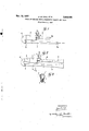
- Figs. 1 and 2 illustrate two forms of the invention.
- Fig. 3 is a cross-section taken along line III-III of Fig. 2.
- the tubular exhaust member 3 develops the expansion of the gases generated in the chamber 1 and from it these gases are expelled in the form of a highspeed jet, suitable for the propulsion by reaction of any movable body on which the apparatus is fixed.
- the aerodynamic valve 2 opens to the opposite side of the exhaust nozzle 3, that is to say towards the front of the movable body to be propelled, the members 2, 1 and 3 being centered on the same axis, the apparatus shown in the drawing comprises a bend 4 at so that the aerodynamic valve has its opening to the rear in the same way as the exhaust nozzle 3.
- the bend 4 can be placed at different points of the path of air proceeding from the inlet orifice 2a, of the aerodynamic valve to the outlet orifice 3a of the exhaust nozzle. It could, for example, be provided in the length of the aerodynamic valve itself, the combustion chamber 1 then being mounted in its usual position, coaxially with the exhaust nozzle 3. However, the arrangement shown in Fig. l, in which the bend 4 is located at the outlet of the combustion chamber is preferable, since at this point the gases have not yet attained a high speed and their deflection can thus take place with a minimum loss of energy.
- the bend 4 is slightly convergent and is joined to the exhaust tube 3 by the most acutely convergent portion 5, which terminates the expansion and the deflection of the jet of gas at the exit from the bend 4.
- the bend 4 is of constant cross-sectional area. It is interposed between a convergent member 6 which follows the chamber 1, and a convergent member 5 which joins it to the exhaust nozzle 3.
- Fig. 2 where the ejectors in question are shown respectively as 7 and 8.
- a pulse jet engine comprising in combination an intermittent firing combustion chamber, an air inlet device connected to one end of said chamber and having an orifice facing towards the rear of said engine, an exhaust pipe extending alongside the combustion chamber and having an outlet facing in the same direction as said orifice, said exhaust pipe being fed solely from said combustion chamber, and a pipe bend of substantially 180 connecting the beginning of the exhaust pipe with the other end of the combustion chamber, to form with said pipe and chamber a constinuous gas conveying duct,
- ning'of the exhaust-pipe is of converging shape.
- An engine as-claimed in claim 5 further comprising two thrust augmenting tubes of converging-diverging 4, shape coaxial with and spaced from the orifice of the air inlet device andthe outlet of the exhaust pipe.
Landscapes
- Engineering & Computer Science (AREA)
- Chemical & Material Sciences (AREA)
- Combustion & Propulsion (AREA)
- Mechanical Engineering (AREA)
- General Engineering & Computer Science (AREA)
- Exhaust Silencers (AREA)
Description
Nov. 12, 1957 J, LE ou. EI'AL 2,812,635
PULSE JET ENGINES 1TH A REARWARDLY OPENING AIR INLET Filed March (5, 1953 1 w ke 47-roRNEY5 United States Patent PULSE JET ENGINES WITH A REARWARDLY OPENING AIR INLET Jean Le Foll, Le Pre-Saint-Gervais, and Jean H. Bertin, N euilly-sur-Seine, France, assignors to Societe N ationale dEtude et de Construction de Moteurs dAviation, Paris, France, a company of France Application March 6 1953, Serial No. 340,834 Claims priority, application France March 11, 1952 6 Claims. (Cl. 60--35.6)
simple tubular members which are constantly open but are formed in such a manner that their resistance to the flow of air towards the combustion chamber is very much lower than their resistance to the flow of the gases from the combustion chamber to the atmosphere. However small the escape of gas to the atmosphere through these aerodynamic valves may be, it is inevitable that it must exist and in a pulse-jet, this gas escape, projected towards the front, causes a counter-thrust which acts in opposition to the propulsive thrust produced by the jet and it is therefore desirable to eliminate it if it is sought to improve the efliciency of the pulse-jet.
It has already been proposed to collect or recover the gases which escape through the areodynamic valve of a pulse-jet, by arranging in front of the inlet orifice of this valve, and spaced at a short distance from it, a tubular member suitably arranged and bent round through 180, in order that the outlet of this tubular member may be directed in the, same direction as the exhaust nozzle of the impulse-jet. Such an arrangement has, however, the disadvantage of increasing the weight of the reactor.
The improvement which forms the object of the present invention overcomes the detrimental effects of the gas escape through the aerodynamic valve or any other type of admission device of an impulse-jet, without it being necessary to provide a tubular recovery member, the principle of which has been referred to above.
According to this improvement, the path followed by the air or gas between the air inlet orifice of the impulsejet and the exhaust orifice includes one or a number of bends so disposed that the air inlet orifice faces in the same direction as the exhaust orifice, the escape of gas through the admission device of the impulse-jet thus producing a postiive thrust which assists that of the gases expelled through the exhaust orifice instead of being opposed to it.
It is of advantage to situate the bend or bends at a part of the impulse-jet at which the gas in movement has a relatively low velocity and, in this respect, an advantageous embodiment is that in which a bend at 180 is provided at the junction of the combustion chamber and the exhaust nozzle, in a zone at which the expansion of the gases is still not entirely complete.
The description which follows below with reference to the attached drawing (which is given by way of example and not in any sense of limitation) will make it quite clear how the invention may be carried into effect.
Figs. 1 and 2 illustrate two forms of the invention.
Fig. 3 is a cross-section taken along line III-III of Fig. 2.
In the pulse jet engine illustrated in Fig. 1, the com bustion chamber 1 with its fuel injector 9 and igniter 10 and the aerodynamic valve 2 are shown, the latter being intended for the admission of air into the combustion 2,812,635 Patented Nov. 12, 1957 chamber in which is maintained the pulsatory combustion. This valve is assumed to be of the type described by the applicants in their U. S. patent application, Serial No. 229,945, filed June 5, 1951, now Patent No. 2,795,931, but it may be of any other type, for example of the type with domed rings described in U. S. patent application, Serial No. 56,582 filed October 26, 1948, now Patent No. 2,670,011. The tubular exhaust member 3 develops the expansion of the gases generated in the chamber 1 and from it these gases are expelled in the form of a highspeed jet, suitable for the propulsion by reaction of any movable body on which the apparatus is fixed. Whilst in the known forms of pulse-jets the aerodynamic valve 2 opens to the opposite side of the exhaust nozzle 3, that is to say towards the front of the movable body to be propelled, the members 2, 1 and 3 being centered on the same axis, the apparatus shown in the drawing comprises a bend 4 at so that the aerodynamic valve has its opening to the rear in the same way as the exhaust nozzle 3.
As can well be understood, the result of this arrangement is that the escape of gases through the aerodynamic valve at the moment of each explosion produces a thrust, the effect of which is additional to that of the gases expelled from the exhaust nozzle 3, the disadvantage of aerodynamic valves in respect of the value of the total thrust developed being thus overcome.
The bend 4 can be placed at different points of the path of air proceeding from the inlet orifice 2a, of the aerodynamic valve to the outlet orifice 3a of the exhaust nozzle. It could, for example, be provided in the length of the aerodynamic valve itself, the combustion chamber 1 then being mounted in its usual position, coaxially with the exhaust nozzle 3. However, the arrangement shown in Fig. l, in which the bend 4 is located at the outlet of the combustion chamber is preferable, since at this point the gases have not yet attained a high speed and their deflection can thus take place with a minimum loss of energy.
The bend may aiso be provided within :the length of the combustion chamber 1 which will thus be folded back on itself.
In the embodiment shown in Fig. 1, the bend 4 is slightly convergent and is joined to the exhaust tube 3 by the most acutely convergent portion 5, which terminates the expansion and the deflection of the jet of gas at the exit from the bend 4.
In the embodiment shown in Fig. 2, the bend 4 is of constant cross-sectional area. It is interposed between a convergent member 6 which follows the chamber 1, and a convergent member 5 which joins it to the exhaust nozzle 3.
The arrangements employing dilution ejectors which have been described by the applicants in their U. S. patent application, Serial No. 229,947, filed June 5, 1951, can be applied equally well to the jet expelled from the nozzle 3,
as described in the above application, as to that delivered from the aerodynamic valve 2. Such an arrangement is shown in Fig. 2 where the ejectors in question are shown respectively as 7 and 8.
What we claim is: p
1. A pulse jet engine comprising in combination an intermittent firing combustion chamber, an air inlet device connected to one end of said chamber and having an orifice facing towards the rear of said engine, an exhaust pipe extending alongside the combustion chamber and having an outlet facing in the same direction as said orifice, said exhaust pipe being fed solely from said combustion chamber, and a pipe bend of substantially 180 connecting the beginning of the exhaust pipe with the other end of the combustion chamber, to form with said pipe and chamber a constinuous gas conveying duct,
ning'of the exhaust-pipe is of converging shape.
3. An engine as claimed in claim 2 wherein the other end of the combustion chamber is of converging shape and the bend of substantially uniform cross-section.-
4. An engine as claimed-in claim 2 wherein-the-bend isof continuously decreasing cross-sectional area.
5.- An engine as claimed in claim 1 wherein the air inlet device is a tubular-duct extending parallel to the exhaust pipe.
6. An engine as-claimed in claim 5 further comprising two thrust augmenting tubes of converging-diverging 4, shape coaxial with and spaced from the orifice of the air inlet device andthe outlet of the exhaust pipe.
References Cited in the file of this patent UNITED STATES PATENTS 2,525,782 Dunbar 2. Oct. 17, 1950 2,574,460 Bohanon Nov. 13, 1951 2,639,580 Stuart May 26, 1953 FOREIGN PATENTS 640,577 I- i'ance- Apr. 2, 1948
Applications Claiming Priority (1)
| Application Number | Priority Date | Filing Date | Title |
|---|---|---|---|
| FR2812635X | 1952-03-11 |
Publications (1)
| Publication Number | Publication Date |
|---|---|
| US2812635A true US2812635A (en) | 1957-11-12 |
Family
ID=9689001
Family Applications (1)
| Application Number | Title | Priority Date | Filing Date |
|---|---|---|---|
| US340834A Expired - Lifetime US2812635A (en) | 1952-03-11 | 1953-03-06 | Pulse jet engines with a rearwardly opening air inlet |
Country Status (1)
| Country | Link |
|---|---|
| US (1) | US2812635A (en) |
Cited By (27)
| Publication number | Priority date | Publication date | Assignee | Title |
|---|---|---|---|---|
| US2998705A (en) * | 1958-07-29 | 1961-09-05 | Carroll D Porter | Pressure gain valveless combustior |
| US3008293A (en) * | 1957-05-18 | 1961-11-14 | Snecma | Intermittently-operating thermo-propulsive duct designed for driving a shaft and applicable to rotary wing aircraft |
| US3438576A (en) * | 1966-10-10 | 1969-04-15 | Litton Systems Inc | Visibility modification method and apparatus |
| US3462955A (en) * | 1967-06-29 | 1969-08-26 | Fairchild Hiller Corp | Pulse jet engine |
| US3768926A (en) * | 1971-11-30 | 1973-10-30 | R Pegg | Pulse jet rotor drive for helicopter |
| US4033120A (en) * | 1975-08-21 | 1977-07-05 | Canadian Patents And Development Limited | Thrust augmenting fluid rectifier for a pulsed combustor |
| US4671056A (en) * | 1986-08-06 | 1987-06-09 | Genz Matthew L R | Pulse-sonic jet nozzle |
| US4962641A (en) * | 1989-02-28 | 1990-10-16 | Elizabeth Ghougasian | Pulse jet engine |
| US20070022740A1 (en) * | 2005-07-27 | 2007-02-01 | Ouellette Richard P | Acoustic pulsejet helmet |
| RU2333377C2 (en) * | 2006-05-31 | 2008-09-10 | Валерий Григорьевич Кехваянц | Method of creating motor vehicle driving force |
| US20080223045A1 (en) * | 2005-07-05 | 2008-09-18 | Luc Laforest | Combustor Configurations |
| RU2334116C1 (en) * | 2006-11-30 | 2008-09-20 | Валерий Григорьевич Кехваянц | Method of creation of vehicle propulsive force and propulsion device based thereon |
| RU2344308C2 (en) * | 2007-03-07 | 2009-01-20 | Валерий Григорьевич Кехваянц | Method of motive power creation in ejector traction booster and ejector traction booster on its basis |
| US20130047625A1 (en) * | 2011-08-22 | 2013-02-28 | Star Drive Propulsion Systems, LLC | Enhanced pulse detonation engine system |
| US9920926B1 (en) | 2017-07-10 | 2018-03-20 | Thermochem Recovery International, Inc. | Pulse combustion heat exchanger system and method |
| US10099200B1 (en) | 2017-10-24 | 2018-10-16 | Thermochem Recovery International, Inc. | Liquid fuel production system having parallel product gas generation |
| US10214418B2 (en) | 2011-09-27 | 2019-02-26 | Thermochem Recovery International, Inc. | Method for converting biomass into fischer-tropsch products with carbon dioxide recycling |
| US10222060B2 (en) | 2016-02-16 | 2019-03-05 | Thermochem Recovery International, Inc. | Two-stage energy-integrated product gas generation system and method |
| US10286431B1 (en) | 2016-03-25 | 2019-05-14 | Thermochem Recovery International, Inc. | Three-stage energy-integrated product gas generation method |
| US10815440B2 (en) | 2010-11-05 | 2020-10-27 | Thermochem Recovery International, Inc. | Systems and methods for producing syngas from a solid carbon-containing substance using a reactor having hollow engineered particles |
| US10995703B2 (en) | 2015-03-19 | 2021-05-04 | North American Wave Engine Corporation | Systems and methods for improving operation of pulse combustors |
| US11370982B2 (en) | 2016-08-30 | 2022-06-28 | Thermochem Recovery International, Inc. | Method of producing liquid fuel from carbonaceous feedstock through gasification and recycling of downstream products |
| US11434851B2 (en) | 2015-12-18 | 2022-09-06 | North American Wave Engine Corporation | Systems and methods for air-breathing wave engines for thrust production |
| US11466223B2 (en) | 2020-09-04 | 2022-10-11 | Thermochem Recovery International, Inc. | Two-stage syngas production with separate char and product gas inputs into the second stage |
| US11555157B2 (en) | 2020-03-10 | 2023-01-17 | Thermochem Recovery International, Inc. | System and method for liquid fuel production from carbonaceous materials using recycled conditioned syngas |
| US11578681B2 (en) | 2015-03-19 | 2023-02-14 | University Of Maryland | Systems and methods for anti-phase operation of pulse combustors |
| US11585532B2 (en) | 2018-04-17 | 2023-02-21 | North American Wave Engine Corporation | Method and apparatus for the start-up and control of pulse combustors using selective injector operation |
Citations (4)
| Publication number | Priority date | Publication date | Assignee | Title |
|---|---|---|---|---|
| FR640577A (en) * | 1926-09-23 | 1928-07-17 | Method and device for producing a gas jet for mechanical work flow | |
| US2525782A (en) * | 1945-08-02 | 1950-10-17 | James Y Dunbar | Shock wave trap for multiple combustion chamber reso-jet motors |
| US2574460A (en) * | 1946-04-08 | 1951-11-13 | Bohanon Hoy Rolla | Valveless intermittent ram-jet engine |
| US2639580A (en) * | 1945-03-21 | 1953-05-26 | James L Stuart | Valveless pulse jet engine |
-
1953
- 1953-03-06 US US340834A patent/US2812635A/en not_active Expired - Lifetime
Patent Citations (4)
| Publication number | Priority date | Publication date | Assignee | Title |
|---|---|---|---|---|
| FR640577A (en) * | 1926-09-23 | 1928-07-17 | Method and device for producing a gas jet for mechanical work flow | |
| US2639580A (en) * | 1945-03-21 | 1953-05-26 | James L Stuart | Valveless pulse jet engine |
| US2525782A (en) * | 1945-08-02 | 1950-10-17 | James Y Dunbar | Shock wave trap for multiple combustion chamber reso-jet motors |
| US2574460A (en) * | 1946-04-08 | 1951-11-13 | Bohanon Hoy Rolla | Valveless intermittent ram-jet engine |
Cited By (49)
| Publication number | Priority date | Publication date | Assignee | Title |
|---|---|---|---|---|
| US3008293A (en) * | 1957-05-18 | 1961-11-14 | Snecma | Intermittently-operating thermo-propulsive duct designed for driving a shaft and applicable to rotary wing aircraft |
| US2998705A (en) * | 1958-07-29 | 1961-09-05 | Carroll D Porter | Pressure gain valveless combustior |
| US3438576A (en) * | 1966-10-10 | 1969-04-15 | Litton Systems Inc | Visibility modification method and apparatus |
| US3462955A (en) * | 1967-06-29 | 1969-08-26 | Fairchild Hiller Corp | Pulse jet engine |
| US3768926A (en) * | 1971-11-30 | 1973-10-30 | R Pegg | Pulse jet rotor drive for helicopter |
| US4033120A (en) * | 1975-08-21 | 1977-07-05 | Canadian Patents And Development Limited | Thrust augmenting fluid rectifier for a pulsed combustor |
| US4671056A (en) * | 1986-08-06 | 1987-06-09 | Genz Matthew L R | Pulse-sonic jet nozzle |
| EP0256711A3 (en) * | 1986-08-06 | 1989-04-05 | Matthew Lewis Reginald Genz | Pulse jet combustor |
| US4962641A (en) * | 1989-02-28 | 1990-10-16 | Elizabeth Ghougasian | Pulse jet engine |
| US8083494B2 (en) | 2005-07-05 | 2011-12-27 | Gestion Serge Benjamin Inc. | Pulse jet engine having an acoustically enhanced ejector system |
| US20080223045A1 (en) * | 2005-07-05 | 2008-09-18 | Luc Laforest | Combustor Configurations |
| US20120100495A1 (en) * | 2005-07-05 | 2012-04-26 | Luc Laforest | Combustor configurations |
| US8312706B2 (en) * | 2005-07-05 | 2012-11-20 | Atlantis Research Labs | Pulse combustor including acoustic elements |
| US7581383B2 (en) * | 2005-07-27 | 2009-09-01 | The Boeing Company | Acoustic pulsejet helmet |
| US20070022740A1 (en) * | 2005-07-27 | 2007-02-01 | Ouellette Richard P | Acoustic pulsejet helmet |
| RU2333377C2 (en) * | 2006-05-31 | 2008-09-10 | Валерий Григорьевич Кехваянц | Method of creating motor vehicle driving force |
| RU2334116C1 (en) * | 2006-11-30 | 2008-09-20 | Валерий Григорьевич Кехваянц | Method of creation of vehicle propulsive force and propulsion device based thereon |
| RU2344308C2 (en) * | 2007-03-07 | 2009-01-20 | Валерий Григорьевич Кехваянц | Method of motive power creation in ejector traction booster and ejector traction booster on its basis |
| US10815440B2 (en) | 2010-11-05 | 2020-10-27 | Thermochem Recovery International, Inc. | Systems and methods for producing syngas from a solid carbon-containing substance using a reactor having hollow engineered particles |
| US20130047625A1 (en) * | 2011-08-22 | 2013-02-28 | Star Drive Propulsion Systems, LLC | Enhanced pulse detonation engine system |
| US10280081B2 (en) | 2011-09-27 | 2019-05-07 | Thermochem Recovery International, Inc. | Unconditioned syngas composition and method of cleaning up same for fischer-tropsch processing |
| US10214418B2 (en) | 2011-09-27 | 2019-02-26 | Thermochem Recovery International, Inc. | Method for converting biomass into fischer-tropsch products with carbon dioxide recycling |
| US12077435B2 (en) | 2011-09-27 | 2024-09-03 | Thermochem Recovery International, Inc. | Method of generating clean syngas |
| US11186483B2 (en) | 2011-09-27 | 2021-11-30 | Thermochem Recovery International, Inc. | Method of producing sulfur-depleted syngas |
| US11760631B2 (en) | 2011-09-27 | 2023-09-19 | Thermochem Recovery International, Inc. | Method of producing a cooled syngas of improved quality |
| US10800655B2 (en) | 2011-09-27 | 2020-10-13 | Thermochem Recovery International, Inc. | Conditioned syngas composition, method of making same and method of processing same to produce fuels and/or fischer-tropsch products |
| US11578681B2 (en) | 2015-03-19 | 2023-02-14 | University Of Maryland | Systems and methods for anti-phase operation of pulse combustors |
| US10995703B2 (en) | 2015-03-19 | 2021-05-04 | North American Wave Engine Corporation | Systems and methods for improving operation of pulse combustors |
| US11434851B2 (en) | 2015-12-18 | 2022-09-06 | North American Wave Engine Corporation | Systems and methods for air-breathing wave engines for thrust production |
| US10222060B2 (en) | 2016-02-16 | 2019-03-05 | Thermochem Recovery International, Inc. | Two-stage energy-integrated product gas generation system and method |
| US11242988B2 (en) | 2016-02-16 | 2022-02-08 | Thermochem Recovery International, Inc. | Two-stage energy-integrated product gas generation system and method |
| US10287519B2 (en) | 2016-03-25 | 2019-05-14 | Thermochem Recovery International, Inc. | Three-stage energy-integrated product gas generation system |
| US10766059B2 (en) | 2016-03-25 | 2020-09-08 | Thermochem Recovery International, Inc. | System and method for recovering inert feedstock contaminants from municipal solid waste during gasification |
| US10286431B1 (en) | 2016-03-25 | 2019-05-14 | Thermochem Recovery International, Inc. | Three-stage energy-integrated product gas generation method |
| US10946423B2 (en) | 2016-03-25 | 2021-03-16 | Thermochem Recovery International, Inc. | Particulate classification vessel having gas distributor valve for recovering contaminants from bed material |
| US11370982B2 (en) | 2016-08-30 | 2022-06-28 | Thermochem Recovery International, Inc. | Method of producing liquid fuel from carbonaceous feedstock through gasification and recycling of downstream products |
| US11634650B2 (en) | 2016-08-30 | 2023-04-25 | Thermochem Recovery International, Inc. | Method of producing liquid fuel from carbonaceous feedstock through gasification and recycling of downstream products |
| US10215401B2 (en) | 2017-07-10 | 2019-02-26 | Thermochem Recovery International, Inc. | Pulse combustion heat exchanger system and method |
| US9920926B1 (en) | 2017-07-10 | 2018-03-20 | Thermochem Recovery International, Inc. | Pulse combustion heat exchanger system and method |
| US10350574B2 (en) | 2017-10-24 | 2019-07-16 | Thermochem Recovery International, Inc. | Method for producing a product gas having component gas ratio relationships |
| US10099200B1 (en) | 2017-10-24 | 2018-10-16 | Thermochem Recovery International, Inc. | Liquid fuel production system having parallel product gas generation |
| US11585532B2 (en) | 2018-04-17 | 2023-02-21 | North American Wave Engine Corporation | Method and apparatus for the start-up and control of pulse combustors using selective injector operation |
| US11592184B2 (en) | 2018-04-17 | 2023-02-28 | North American Wave Engine Corporation | Method and apparatus for the start-up and control of pulse combustors using selective injector operation |
| US11555157B2 (en) | 2020-03-10 | 2023-01-17 | Thermochem Recovery International, Inc. | System and method for liquid fuel production from carbonaceous materials using recycled conditioned syngas |
| US12187969B2 (en) | 2020-03-10 | 2025-01-07 | Thermochem Recovery International, Inc. | System and method for liquid fuel production from carbonaceous materials using recycled conditioned syngas |
| US12480061B2 (en) | 2020-03-10 | 2025-11-25 | Thermochem Recovery International, Inc. | System and method for liquid fuel production from carbonaceous materials using recycled conditioned syngas |
| US11466223B2 (en) | 2020-09-04 | 2022-10-11 | Thermochem Recovery International, Inc. | Two-stage syngas production with separate char and product gas inputs into the second stage |
| US11760949B2 (en) | 2020-09-04 | 2023-09-19 | Thermochem Recovery International, Inc. | Two-stage syngas production with separate char and product gas inputs into the second stage |
| US12203040B2 (en) | 2020-09-04 | 2025-01-21 | Thermochem Recovery International, Inc. | Two-stage syngas production with separate char and product gas inputs into the second stage |
Similar Documents
| Publication | Publication Date | Title |
|---|---|---|
| US2812635A (en) | Pulse jet engines with a rearwardly opening air inlet | |
| US3027710A (en) | Methods and apparatus for suppressing jet noise | |
| US2610465A (en) | Auxiliary thrust means for jetpropelled aircraft | |
| US2770944A (en) | Variable area reaction nozzle movable from convergent to convergent-di-vergent form | |
| US3143401A (en) | Supersonic fuel injector | |
| US3432100A (en) | Ejecting nozzle for propellers provided with a plurality of driving streams and,more particularly,two driving streams | |
| US2750733A (en) | Jet propulsion engine with pulse jet units | |
| US3524588A (en) | Silencer for aircraft jet engines | |
| US2971327A (en) | Discharge control of an overexpanding propulsion nozzle | |
| US2795931A (en) | Aerodynamic valve arrangement | |
| US3062003A (en) | Variable area exhaust nozzle | |
| GB1122910A (en) | Improvements in supersonic convergent-divergent jet exhaust nozzle | |
| US3454227A (en) | Free floating articulate ejector nozzle | |
| US3346193A (en) | Supersonic ejector type exhaust nozzle | |
| US2882679A (en) | Augmenter type afterburner for jet propelled aircraft | |
| US2914916A (en) | Arrangement for controlling the flow of a fluid by means of an auxiliary flow | |
| CN114165361A (en) | Injection rocket ramjet engine combustion chamber and self-adaptive fuel injection method | |
| US2825202A (en) | Pipes traversed by pulsating flow gases | |
| GB1100099A (en) | Improvements in convergent-divergent jet exhaust nozzle for supersonic aircraft | |
| US2870600A (en) | Variable ejector for iris nozzles | |
| US3780827A (en) | Gas turbine exhaust nozzle | |
| US2834181A (en) | Jet propulsion unit comprising pulse jet units having ejector tubes within a ramjet unit | |
| US3528247A (en) | Exhaust system for vtol aircraft | |
| US3514957A (en) | High speed propulsion engine | |
| US3076309A (en) | Aircraft jet propulsion apparatus with thrust reversing means |