US2811368A - Vertically and laterally adjustable wheel mounting means for potato diggers - Google Patents
Vertically and laterally adjustable wheel mounting means for potato diggers Download PDFInfo
- Publication number
- US2811368A US2811368A US546188A US54618855A US2811368A US 2811368 A US2811368 A US 2811368A US 546188 A US546188 A US 546188A US 54618855 A US54618855 A US 54618855A US 2811368 A US2811368 A US 2811368A
- Authority
- US
- United States
- Prior art keywords
- wheel
- bracket
- laterally
- openings
- frame
- Prior art date
- Legal status (The legal status is an assumption and is not a legal conclusion. Google has not performed a legal analysis and makes no representation as to the accuracy of the status listed.)
- Expired - Lifetime
Links
Images
Classifications
-
- A—HUMAN NECESSITIES
- A01—AGRICULTURE; FORESTRY; ANIMAL HUSBANDRY; HUNTING; TRAPPING; FISHING
- A01D—HARVESTING; MOWING
- A01D33/00—Accessories for digging harvesters
Definitions
- the present invention relates generally to agricultural implements and more particularly to new and improved Wheel mounting means for such implements as potato diggers and the like.
- the objects and general nature of the present invention is a provision of a wheel mounting means for agricultural implements and the like in which the supporting wheels for the implement may be adjusted b-oth vertically and laterally relative to the main frame of the implement so as to provide for disposing the frame at the desired level, usually as low as possible in the case of potato diggers, and also to provide the desired or necessary tread spacing, such as to accommodate different row spacings. More specifically, it is a feature of the present invention to provide a wheel carrier and means connected with the latter in different positions both laterally and vertically relative to the main frame of the implement and to secure and retain the desired adjustment by simple, convenient and easily operated means.
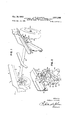
- Fig. l is a fragmentary perspective of a portion of a potato digger frame in which the principles of the present 8 invention have been incorporated.
- Fig. 2 is an enlarged perspective view showing the wheel mounting means in the position disposing the supporting wheel as shown in Fig. 1.
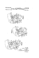
- Fig. 3 is a view similar to Fig. 2 showing the wheel mounting means arranged to provide a somewhat increased tread spacing for the wheels, Fig. 3 showing the mounting parts for the widest tread spacing available and with the frame in an intermediate position vertically.
- Fig. 4 is a view similar to Figs. 2 and 3, showing the wheel mounting means arranged for the lowest position of the main frame and an intermediate tread spacing.
- Fig. 5 is a view similar to Fig. 4, showing the wheel mounting means arranged for a minimum tread spacing, with the frame in the lowest position vertically.
- the potato digger in which the principles of the present invention have been shown by way of illustration is indicated in its entirety by the reference numeral and includes a main frame 11 made up of right and left hand frame angles 12 and other longitudinal and transverse frame parts not shown, the frame 11 being supported on a pair of ground wheels 14.
- the wheels 14 are mounted on a wheel frame assembly 20 that comprises a transverse pipe member 21 and a wheel mounting bracket 22 at each end of the pipe member 21.
- the wheel frame assembly 20 is rigidly connected with and, in effect, forms an integral part of the main frame 11.
- Fig. 2 et seq. only one of the wheel mounting brackets 22 is shown, since they are substantially identical.
- Each includes a vertical plate 25 welded or otherwise secured to the adjacent end of the pipe member 21 and also securely fixed, as by bolts 26, to the adjacent portions of the associated frame angle 12.
- a vertical flange section 28 Secured to each side edge portion of the vertical plate 25 is a vertical flange section 28 having a plurality of openings 29 therein. More specifically, it will be noted that each of the vertical flanges 28 is provided with four openings adjacent the plate 26, these openings being arranged in vertically spaced apart relation, and a set of outer openings, also arranged in vertically spaced relation, the outer openings being indicated by the reference numeral 29a.
- the plate 25 is also provided with a plurality of openings aranged in vertically spaced apart relation, two openings 31 being disposed at one side of the center line of the plate 25 while the other openings 32 are disposed at the other side.
- each of the bracket means 22 provides four optional positions, spaced apart generally vertically, for receiving a through bolt 35 in a lateral position closely adjacent the plane of the associated plate 25.
- each bracket 22 provides for two laterally outward positions for the bolt 35, the latter position being defined by the vertically spaced openings 29a.
- each bolt 35 Disposed on each bolt 35 is a wheel carrier bracket 38 that comprises a lower spindle section 41 on which the hub 14a of the associated ground wheel 14 is journaled for rotation, an intermediate mounting section 42 that comprises a strap member turned upwardly at its ends and apertured for reception of the through bolt 35, the strap member 42 being welded or otherwise securely fixed to the laterally inner portion of the associated spindle section 41, and an upwardly extending arm section 44 that also is securely welded or otherwise fixed to the intermediate section 42.
- a wheel carrier bracket 38 Disposed on each bolt 35 is a wheel carrier bracket 38 that comprises a lower spindle section 41 on which the hub 14a of the associated ground wheel 14 is journaled for rotation, an intermediate mounting section 42 that comprises a strap member turned upwardly at its ends and apertured for reception of the through bolt 35, the strap member 42 being welded or otherwise securely fixed to the laterally inner portion of the associated spindle section 41, and an upwardly extending arm section 44 that also is securely welded or otherwise fixed to the intermediate section 42.
- the outer end of the arm 44 is apertured to receive a short bolt 45 that connects the arm section 44 in either of two positions to a vertically adjustable angle bracket 46, the laterally outer or shorter leg 47 of which'is provided with two apertures that, in Figures 2, 4 and 5, receive the associated bolt 45 in either of two laterally spaced apart positions, the other or longer leg portion 48 also having two openings, either of which, as shown in Figures 2, 4 and 5, may receive a bolt 49 that connects the angle bracket 46 to the plate member 25 at one of the openings 31, 32 provided therein.
- the two openings in the shorter leg section 47 of the angle bracket 46 are indicated at 51 and 52 and the two openings in the longer leg 48 are indicated at 53 and 54.
- the wheel carrier 38 When the wheel carrier 38 is mounted on the associated bolt 35, the wheel carrier may be angularly adjusted, as shown in Figures 2, 4 and 5, by fixing the upper end of the arm 44 to the bracket leg 47 in either of two positions, as determined by whether the bolt 45 is disposed in the laterally inner opening 51 ( Figure 2) or the laterally outer opening 52 ( Figure 5) of the bracket 46. It will also be noted that since the bolt 35 may be disposed in any registering pair of vertically spaced openings 29 at the laterally inner portions of the apertured parts 28, the frame may be raised or lowered, as desired, relative to the associated wheels 14 by changing the position of the bolts 35.
- the angle bracket 46 is reversed so that the leg 47 ,(Fig, 3), or,the,leg 48.iFigs..2,...4 and 5), is disposed Forlpotato. diggers and'similar implements, it is usually J desirable to havethe main frame as low as possiblerelative to the ground wheels sothat the. distance through which the potatoes fall to tbe'ground is kept to adesirable minimum. Therefore, for the lowest possible position ofa-themain frame, the bolts are placed in the uppermost openings 29, as shown in Fig.
- the wheels 14 . are arranged gener-v ally vertically, which is done byplacing the bolts in the laterally inner openings Slinthe associated angle brackets 46, as shownin Figs 4.v
- thebolts 45 aredisposed in the withnthe ,supportingnbracket .as. ,a v.center, and, means con: nected with said brackets to hold said wheel carrier bracket in selected angular position relative to said supporting bracket.
- a supporting bracket having a pair of vertical flanges provided with vertically spacedapart apertures, awheel carrier bracket having a laterally outwardlvextending axle section and an uplaterally outermost opening 52, which serves to tilt the wheels 14 laterally inwardly at their lower portions, the corresponding positions of :the wheel carrier brackets 38 being indicated in Pig. 5.
- the bolts 35 are removed and the wheel carrier brackets 38 mounted in a laterally outer position relative to the aperturcd flanges 28 by disposing the bolts 35 in one set of outer openings 2%, as shown in Fig. 3.
- the carrier brackets 38 are disposed in this position, it is necessary to rearrange the brackets46 so as to dispose thelonger legs 48 laterally outwardly and place the bolts 45' arranged in the laterally outer openings 54 of the associatedja'ngle brackets 46, in which position of the.
- wheel carrier brackets 46 the wheels 14 are disposed vertically.
- groundwheels may be adjusted both vertically and laterally relative to the associated main frame.
- the means providing for different wheel spacings, both laterally and vertically does not entail the use of spare parts or the like, which are apt to become mislaid or otherwise unavailable at the time they are most needed.
- support means therefor comprising a supporting bracket, a wheel carrier bracket, means fixing said brackets together in different vertically adjusted positions said Wheel carrier bracket being pivotally connected with said. supporting bracket, and means fixing said wheel carrier bracket to the supporting bracket indifferent angular positions.
- sup port means therefor comprising a supporting bracket having a vertically extending :apertured section, the apertures being spaced apart both vertically and laterally, a wheel. carrier bracket having a part disposable in anyone of' said apertures forboth. vertical and lateralyadjustment,
- a. wheel carrier bracket having a part disposable in any .oneof; saidv apertures to determine thevertical position ofathe wheel; carrier, bracket .relatiYe toitheesupporting bracket; said. wheelearrier bracketbeing swingable aboutitsconnection;
- frame means including a pair of vertical partsspacedapart in a fore-and-aft direction, a rockable wheel carrier having a spindle section and an arm section, a wheel journaled on said spindle section, means pivotally mounting said wheel carrier on said parts for swinging relative thereto to dispose the lower portion of the wheel in different lateral positions relative to said frame means,.a laterally extending part connected to said. frame means between said spaced apart vertical parts and extending. laterally outwardly therefrom, and means-connecting the outer end of said arm section with said laterally outwardlyzextending part in different lateral positions.
- the invention set forth inclaim 5 further characterized by the means pivotally-niounting said Wheel carrier comprising apivot member removably associated with said wheel carrier-and said par-ts, the latter having a plurality of vertically spaced apartopenings to receive said pivot member in different vertical positions, said frame means havingaplurality-of vertically spaced openings to receive said laterally extending part so as to dispose the latter also indifferent vertical positions.
- frame means including'apair. .of:vertical parts spaced apart. in a fore-and aft direction, a rockable wheel.v carrier having a spindle section and an arm section, a wheel journaled on'said spindle section, the outer end. of said arm. section. being apertured, means pivotally mounting said wheel carrier. on said parts and disposed generally. between the latter for swinging relativethereto to dispose the'lower POI-1 tion of.the-.wheel. in-difierentlateral positions relative.
- tionsand an arm. section a.wheel journaled on said spindlev section, means pivotally mounting said wheel carrier-on said .parts for swinging relative thereto to disposethelower portionrof the .wheel in different lateral positions, relative to said .frame means, a bracket fixed to said frame means and having a laterally outwardly extending section, and means connecting the outer end of said arm section with the laterally outwardly extendingsection of said bracket in different lateral positions.
Landscapes
- Life Sciences & Earth Sciences (AREA)
- Environmental Sciences (AREA)
- Agricultural Machines (AREA)
Description
Oct. 29, 1957 H. F. CLAUSEN 2,811,368
VERTICALLY AND LATERALLY ADJUSTABLE WHEEL MOUNTING MEANS FOR POTATO DIGGERS Filed Nov. 10, 1955 2 Sheets-Sheer. 1
INVENTOR. HOWARD F. CLAUSEN iTORNEYS Oct. 29, 1957 H. F. CLAUSEN 2,811,368
VERTICALLY AND LATERALLY ADJUSTABLE WHEEL MOUNTING MEANS FOR POTATO DIGGERS Filed Nov. 10, 1955 2 Sheets-Sheet 2 FIG.4
INVENTOR.
HOWARD F. CLAUSEN ATTORNEYS United States Patent VERTIfiALLY AND LATERALLY ADJUSTABLE WHEEL MOUNTING MEANS FOR POTATO DIGGERS Howard F. Clausen, Moiine, Ill., assignor to Deere & Company, Moline, 111., a corporation of Illinois Application November 10, 1955, Serial No. 546,188 10 Claims. (Cl. 280-43) The present invention relates generally to agricultural implements and more particularly to new and improved Wheel mounting means for such implements as potato diggers and the like.
The objects and general nature of the present invention is a provision of a wheel mounting means for agricultural implements and the like in which the supporting wheels for the implement may be adjusted b-oth vertically and laterally relative to the main frame of the implement so as to provide for disposing the frame at the desired level, usually as low as possible in the case of potato diggers, and also to provide the desired or necessary tread spacing, such as to accommodate different row spacings. More specifically, it is a feature of the present invention to provide a wheel carrier and means connected with the latter in different positions both laterally and vertically relative to the main frame of the implement and to secure and retain the desired adjustment by simple, convenient and easily operated means. Particularly, it is a feature of this invention to provide a wheel carrier that can be adjusted vertically relative to the main frame, and also adjustable angularly and, in addition, laterally, thereby providing a plurality of different lateral and vertical positions in which the supporting wheels may be arranged, as required.
These and other objects and advantages of the present invention will be apparent to those skilled in the art after a consideration of the following detailed description of the preferred structure embodiment, in which the principles of the present invention have been incorporated, taken in conjunction with the accompanying drawings in which an embodiment has been illustrated.
In the drawings:
Fig. l is a fragmentary perspective of a portion of a potato digger frame in which the principles of the present 8 invention have been incorporated.
Fig. 2 is an enlarged perspective view showing the wheel mounting means in the position disposing the supporting wheel as shown in Fig. 1.
Fig. 3 is a view similar to Fig. 2 showing the wheel mounting means arranged to provide a somewhat increased tread spacing for the wheels, Fig. 3 showing the mounting parts for the widest tread spacing available and with the frame in an intermediate position vertically.
Fig. 4 is a view similar to Figs. 2 and 3, showing the wheel mounting means arranged for the lowest position of the main frame and an intermediate tread spacing.
Fig. 5 is a view similar to Fig. 4, showing the wheel mounting means arranged for a minimum tread spacing, with the frame in the lowest position vertically.
Referring first to Fig. l, the potato digger in which the principles of the present invention have been shown by way of illustration is indicated in its entirety by the reference numeral and includes a main frame 11 made up of right and left hand frame angles 12 and other longitudinal and transverse frame parts not shown, the frame 11 being supported on a pair of ground wheels 14. As will be best seen in Fig. l, the wheels 14 are mounted on a wheel frame assembly 20 that comprises a transverse pipe member 21 and a wheel mounting bracket 22 at each end of the pipe member 21. The wheel frame assembly 20 is rigidly connected with and, in effect, forms an integral part of the main frame 11. In the detail views, Fig. 2 et seq., only one of the wheel mounting brackets 22 is shown, since they are substantially identical. Each includes a vertical plate 25 welded or otherwise secured to the adjacent end of the pipe member 21 and also securely fixed, as by bolts 26, to the adjacent portions of the associated frame angle 12. Secured to each side edge portion of the vertical plate 25 is a vertical flange section 28 having a plurality of openings 29 therein. More specifically, it will be noted that each of the vertical flanges 28 is provided with four openings adjacent the plate 26, these openings being arranged in vertically spaced apart relation, and a set of outer openings, also arranged in vertically spaced relation, the outer openings being indicated by the reference numeral 29a. The plate 25 is also provided with a plurality of openings aranged in vertically spaced apart relation, two openings 31 being disposed at one side of the center line of the plate 25 while the other openings 32 are disposed at the other side.
Each of the bracket means 22 provides four optional positions, spaced apart generally vertically, for receiving a through bolt 35 in a lateral position closely adjacent the plane of the associated plate 25. In addition, each bracket 22 provides for two laterally outward positions for the bolt 35, the latter position being defined by the vertically spaced openings 29a. Disposed on each bolt 35 is a wheel carrier bracket 38 that comprises a lower spindle section 41 on which the hub 14a of the associated ground wheel 14 is journaled for rotation, an intermediate mounting section 42 that comprises a strap member turned upwardly at its ends and apertured for reception of the through bolt 35, the strap member 42 being welded or otherwise securely fixed to the laterally inner portion of the associated spindle section 41, and an upwardly extending arm section 44 that also is securely welded or otherwise fixed to the intermediate section 42. The outer end of the arm 44 is apertured to receive a short bolt 45 that connects the arm section 44 in either of two positions to a vertically adjustable angle bracket 46, the laterally outer or shorter leg 47 of which'is provided with two apertures that, in Figures 2, 4 and 5, receive the associated bolt 45 in either of two laterally spaced apart positions, the other or longer leg portion 48 also having two openings, either of which, as shown in Figures 2, 4 and 5, may receive a bolt 49 that connects the angle bracket 46 to the plate member 25 at one of the openings 31, 32 provided therein. The two openings in the shorter leg section 47 of the angle bracket 46 are indicated at 51 and 52 and the two openings in the longer leg 48 are indicated at 53 and 54. When the wheel carrier 38 is mounted on the associated bolt 35, the wheel carrier may be angularly adjusted, as shown in Figures 2, 4 and 5, by fixing the upper end of the arm 44 to the bracket leg 47 in either of two positions, as determined by whether the bolt 45 is disposed in the laterally inner opening 51 (Figure 2) or the laterally outer opening 52 (Figure 5) of the bracket 46. It will also be noted that since the bolt 35 may be disposed in any registering pair of vertically spaced openings 29 at the laterally inner portions of the apertured parts 28, the frame may be raised or lowered, as desired, relative to the associated wheels 14 by changing the position of the bolts 35. Whenever the bolt 35 is changed vertically in the apertured bracket 28, it is also necessary to change the angle bracket 46 in the openings 31, 32 so as to correspond to the position of the bolt 35. When either of the openings 31 is to be used, the angle bracket 46 is reversed so that the leg 47 ,(Fig, 3), or,the,leg 48.iFigs..2,...4 and 5), is disposed Forlpotato. diggers and'similar implements, it is usually J desirable to havethe main frame as low as possiblerelative to the ground wheels sothat the. distance through which the potatoes fall to tbe'ground is kept to adesirable minimum. Therefore, for the lowest possible position ofa-themain frame, the bolts are placed in the uppermost openings 29, as shown in Fig. .4, and for an intermediate tread spacing, the wheels 14 .are arranged gener-v ally vertically, which is done byplacing the bolts in the laterally inner openings Slinthe associated angle brackets 46, as shownin Figs 4.v However, if a smaller tread spacing is desired, thebolts 45 aredisposed in the withnthe ,supportingnbracket .as. ,a v.center, and, means con: nected with said brackets to hold said wheel carrier bracket in selected angular position relative to said supporting bracket.
4. In an agricultural implement, a supporting bracket, having a pair of vertical flanges provided with vertically spacedapart apertures, awheel carrier bracket having a laterally outwardlvextending axle section and an uplaterally outermost opening 52, which serves to tilt the wheels 14 laterally inwardly at their lower portions, the corresponding positions of :the wheel carrier brackets 38 being indicated in Pig. 5.
If a wider tread spacing should be desired, wider than that provided by the parts shown in Fig, 2, also Fig. 4, for example, the bolts 35 are removed and the wheel carrier brackets 38 mounted in a laterally outer position relative to the aperturcd flanges 28 by disposing the bolts 35 in one set of outer openings 2%, as shown in Fig. 3. When the carrier brackets 38 are disposed in this position, it is necessary to rearrange the brackets46 so as to dispose thelonger legs 48 laterally outwardly and place the bolts 45' arranged in the laterally outer openings 54 of the associatedja'ngle brackets 46, in which position of the.
wheel carrier brackets 46 the wheels 14 are disposed vertically.
Thus, I have provided a simple arrangement whereby, in'a potato digger or the like, the groundwheels may be adjusted both vertically and laterally relative to the associated main frame. It is also to be noted that the means providing for different wheel spacings, both laterally and vertically, does not entail the use of spare parts or the like, which are apt to become mislaid or otherwise unavailable at the time they are most needed.
While I have shown and described above the preferred structure in which the principles of the present invention have been incorporated-it is to be understood that my invention is not to be limited to the particular details, shown and described :above, but that, in fact, widely different means may be employed in the practice of the broader aspects of. my invention.
What I claim, therefore, and desire to secure by Letters Patent is:
1. In an agricultural implement, support means therefor comprising a supporting bracket, a wheel carrier bracket, means fixing said brackets together in different vertically adjusted positions said Wheel carrier bracket being pivotally connected with said. supporting bracket, and means fixing said wheel carrier bracket to the supporting bracket indifferent angular positions.
2., In an agricultural implement including a frame, sup port means therefor comprising a supporting bracket having a vertically extending :apertured section, the apertures being spaced apart both vertically and laterally, a wheel. carrier bracket having a part disposable in anyone of' said apertures forboth. vertical and lateralyadjustment,
and means connected with said brackets at points spaced from said apertures to hold said wheel carrier bracket in selected angular position relative to said supporting,
bracket.
3. In an agricultural implement including a frame, support means therefor comprising a supporting bracket having a vertically extending apertured section, the apertures being spaced apart both vertically and laterally, a. wheel carrier bracket having a part disposable in any .oneof; saidv apertures to determine thevertical position ofathe wheel; carrier, bracket .relatiYe toitheesupporting bracket; said. wheelearrier bracketbeing swingable aboutitsconnection;
wardly extending arm section, pivot means carried by said wheel carrier bracket and disposable in selected flange openings, and means-selectively fixing the outer .end ofsaid arm'section indifferentlateral positions to said supporting. :bracket,: said;.last-named means being attachable in different vertical positions to said supporting bracket in steps corresponding to the vertical spacing of said apertures.
5. In anagricultural implement, frame means including a pair of vertical partsspacedapart in a fore-and-aft direction, a rockable wheel carrier having a spindle section and an arm section, a wheel journaled on said spindle section, means pivotally mounting said wheel carrier on said parts for swinging relative thereto to dispose the lower portion of the wheel in different lateral positions relative to said frame means,.a laterally extending part connected to said. frame means between said spaced apart vertical parts and extending. laterally outwardly therefrom, and means-connecting the outer end of said arm section with said laterally outwardlyzextending part in different lateral positions.
6'. The invention set forth inclaim 5, further characterized by the means pivotally-niounting said Wheel carrier comprising apivot member removably associated with said wheel carrier-and said par-ts, the latter having a plurality of vertically spaced apartopenings to receive said pivot member in different vertical positions, said frame means havingaplurality-of vertically spaced openings to receive said laterally extending part so as to dispose the latter also indifferent vertical positions.
7; In anagricultural implement, frame means including'apair. .of:vertical parts spaced apart. in a fore-and aft direction, a rockable wheel.v carrier having a spindle section and an arm section, a wheel journaled on'said spindle section, the outer end. of said arm. section. being apertured, means pivotally mounting said wheel carrier. on said parts and disposed generally. between the latter for swinging relativethereto to dispose the'lower POI-1 tion of.the-.wheel. in-difierentlateral positions relative.
tionsand an arm. section, a.wheel journaled on said spindlev section, means pivotally mounting said wheel carrier-on said .parts for swinging relative thereto to disposethelower portionrof the .wheel in different lateral positions, relative to said .frame means, a bracket fixed to said frame means and having a laterally outwardly extending section, and means connecting the outer end of said arm section with the laterally outwardly extendingsection of said bracket in different lateral positions.
9. In an agricultural implement, frame means including a pair of vertical .parts spaced apart in a fore-andaftdirectionand eachhaving laterally and vertically spaced apart=openings, a rockable wheel carrier having a spindle section and. an arm section, a wheel journaled on said spindle section, means adapted to be received ina selected one .of said openings in each of said parts for'pivotally mounting said .wheel carrier on said parts foreboth llateral adjustment and for swinging relative thereto .tosdrspose ;the lower portionof the wheel in ditfering a pair of vertical parts spaced apart in a fore-and-aft 5 direction, a rockable wheel carrier having a spindle section and an arm section, a wheel journaled on said spindle section, means pivotally mounting said wheel carrier on said parts for swinging relative thereto to dispose the lower portion of the wheel in difierent lateral positions 10 relative to said frame means, said pivotal mounting means comprising a pivot member removably associated with said wheel carrier and said parts, the latter having a plurality of vertically spaced apart openings to re- 6 ceive said pivot member in different vertical positions, and means connecting the outer end of said arm section with said frame means in dilierent lateral positions including means vertically adjustable relative to said frame means so as to accommodate changes in the vertical position of said pivot member and said wheel carrier.
References Cited in the file of this patent UNITED STATES PATENTS 1,396,128
Priority Applications (1)
| Application Number | Priority Date | Filing Date | Title |
|---|---|---|---|
| US546188A US2811368A (en) | 1955-11-10 | 1955-11-10 | Vertically and laterally adjustable wheel mounting means for potato diggers |
Applications Claiming Priority (1)
| Application Number | Priority Date | Filing Date | Title |
|---|---|---|---|
| US546188A US2811368A (en) | 1955-11-10 | 1955-11-10 | Vertically and laterally adjustable wheel mounting means for potato diggers |
Publications (1)
| Publication Number | Publication Date |
|---|---|
| US2811368A true US2811368A (en) | 1957-10-29 |
Family
ID=24179246
Family Applications (1)
| Application Number | Title | Priority Date | Filing Date |
|---|---|---|---|
| US546188A Expired - Lifetime US2811368A (en) | 1955-11-10 | 1955-11-10 | Vertically and laterally adjustable wheel mounting means for potato diggers |
Country Status (1)
| Country | Link |
|---|---|
| US (1) | US2811368A (en) |
Cited By (5)
| Publication number | Priority date | Publication date | Assignee | Title |
|---|---|---|---|---|
| US5046579A (en) * | 1990-08-13 | 1991-09-10 | Anderson Jack W | Wheel mounting apparatus |
| US5083803A (en) * | 1990-11-30 | 1992-01-28 | Crown Equipment Corporation | Materials handling vehicle using either cusion or pneumatic tires |
| US5671934A (en) * | 1995-08-30 | 1997-09-30 | Mattel, Inc. | Adjustable axle mounting assembly for children's ride-on vehicles |
| US20040238658A1 (en) * | 2003-02-03 | 2004-12-02 | David Bryan | Kit and method for high clearance conversion of a vehicle |
| US20090077806A1 (en) * | 2006-04-27 | 2009-03-26 | Allen Kenneth L | Tire replacement system for compact tractor |
Citations (3)
| Publication number | Priority date | Publication date | Assignee | Title |
|---|---|---|---|---|
| US1396128A (en) * | 1921-02-03 | 1921-11-08 | Otto E Kopplin | Stub-axle adjustment device |
| US1633151A (en) * | 1926-01-02 | 1927-06-21 | Roy J Winsor | Leaning wheel |
| US2709116A (en) * | 1950-10-04 | 1955-05-24 | Case Co J I | Journal for a transport wheel |
-
1955
- 1955-11-10 US US546188A patent/US2811368A/en not_active Expired - Lifetime
Patent Citations (3)
| Publication number | Priority date | Publication date | Assignee | Title |
|---|---|---|---|---|
| US1396128A (en) * | 1921-02-03 | 1921-11-08 | Otto E Kopplin | Stub-axle adjustment device |
| US1633151A (en) * | 1926-01-02 | 1927-06-21 | Roy J Winsor | Leaning wheel |
| US2709116A (en) * | 1950-10-04 | 1955-05-24 | Case Co J I | Journal for a transport wheel |
Cited By (8)
| Publication number | Priority date | Publication date | Assignee | Title |
|---|---|---|---|---|
| US5046579A (en) * | 1990-08-13 | 1991-09-10 | Anderson Jack W | Wheel mounting apparatus |
| US5083803A (en) * | 1990-11-30 | 1992-01-28 | Crown Equipment Corporation | Materials handling vehicle using either cusion or pneumatic tires |
| US5671934A (en) * | 1995-08-30 | 1997-09-30 | Mattel, Inc. | Adjustable axle mounting assembly for children's ride-on vehicles |
| US20040238658A1 (en) * | 2003-02-03 | 2004-12-02 | David Bryan | Kit and method for high clearance conversion of a vehicle |
| US7284630B2 (en) * | 2003-02-03 | 2007-10-23 | Spray Monsters Manufacturing Inc. | Kit and method for high clearance conversion of a vehicle |
| US20090077806A1 (en) * | 2006-04-27 | 2009-03-26 | Allen Kenneth L | Tire replacement system for compact tractor |
| US8056202B2 (en) | 2006-04-27 | 2011-11-15 | Bridgestone Americas Tire Operations, Llc | Tire replacement system for compact tractor |
| US8826508B2 (en) | 2006-04-27 | 2014-09-09 | Bridgestone Americas Tire Operations, Llc | Tire replacement system for four-wheel-drive compact tractor |
Similar Documents
| Publication | Publication Date | Title |
|---|---|---|
| US2564201A (en) | Wheel adjustment for lawn mowers | |
| US2447354A (en) | Rotary side delivery rake | |
| US20120011822A1 (en) | Agricultural header transport kit | |
| US2811368A (en) | Vertically and laterally adjustable wheel mounting means for potato diggers | |
| US2711624A (en) | Mowing attachment for a tractor | |
| US2064480A (en) | Bean cutter | |
| US2616349A (en) | Integral tool carrier | |
| US9883629B2 (en) | Ground treatment device | |
| US2403401A (en) | Side delivery rake | |
| US2982081A (en) | Agricultural implement and mounting means therefor | |
| US2754647A (en) | Mounted agricultural implement transport and depth control | |
| US2259893A (en) | Corn picker | |
| US2654207A (en) | Combine having side hill platform adjustments | |
| US3052306A (en) | Multiple purpose plow | |
| US2584012A (en) | Transplanter attachment | |
| US3589116A (en) | Reel mower with adjustable support | |
| US2559920A (en) | Platform for lawn mowers | |
| US2938324A (en) | Rotary trash rake | |
| US2817943A (en) | Tilting, raising and lowering mechanism for windrow harvester platforms | |
| US2224051A (en) | Planter attachment | |
| US3202119A (en) | Covering devices for grain drills | |
| US2692543A (en) | Lister plow | |
| US3526342A (en) | Applicator apparatus attachable to a wheeled agricultural implement | |
| US2010287A (en) | Straw spreader attachment | |
| US2398389A (en) | Windrower |