US2808564A - Phase detector fault indicator - Google Patents
Phase detector fault indicator Download PDFInfo
- Publication number
- US2808564A US2808564A US598169A US59816956A US2808564A US 2808564 A US2808564 A US 2808564A US 598169 A US598169 A US 598169A US 59816956 A US59816956 A US 59816956A US 2808564 A US2808564 A US 2808564A
- Authority
- US
- United States
- Prior art keywords
- phase
- detector
- input
- capacitor
- output
- Prior art date
- Legal status (The legal status is an assumption and is not a legal conclusion. Google has not performed a legal analysis and makes no representation as to the accuracy of the status listed.)
- Expired - Lifetime
Links
Images
Classifications
-
- H—ELECTRICITY
- H03—ELECTRONIC CIRCUITRY
- H03L—AUTOMATIC CONTROL, STARTING, SYNCHRONISATION OR STABILISATION OF GENERATORS OF ELECTRONIC OSCILLATIONS OR PULSES
- H03L7/00—Automatic control of frequency or phase; Synchronisation
- H03L7/06—Automatic control of frequency or phase; Synchronisation using a reference signal applied to a frequency- or phase-locked loop
- H03L7/08—Details of the phase-locked loop
- H03L7/085—Details of the phase-locked loop concerning mainly the frequency- or phase-detection arrangement including the filtering or amplification of its output signal
- H03L7/095—Details of the phase-locked loop concerning mainly the frequency- or phase-detection arrangement including the filtering or amplification of its output signal using a lock detector
-
- H—ELECTRICITY
- H03—ELECTRONIC CIRCUITRY
- H03L—AUTOMATIC CONTROL, STARTING, SYNCHRONISATION OR STABILISATION OF GENERATORS OF ELECTRONIC OSCILLATIONS OR PULSES
- H03L7/00—Automatic control of frequency or phase; Synchronisation
- H03L7/06—Automatic control of frequency or phase; Synchronisation using a reference signal applied to a frequency- or phase-locked loop
- H03L7/08—Details of the phase-locked loop
Definitions
- This invention relates to means for indicating faults in the operation of a phase detector such as when its inputs have insuicient amplitude or when they are not in phase-lock.
- Phase detectors are commonly used in frequencystabilization systems. For example, frequency-stabilization systems often use a phase detector to simultaneously compare the output frequency of a variable oscillator to a more stable frequency, such as may be obtained from a crystal-controlled source. The variable-oscillator frequency and a selected crystal harmonic are therefore provided as the two inputs of the phase-detector circuit.
- a correcting device such as a feedback-controlled system, may be controlled by the output of the phase detector to maintain the variable-oscillator frequency in exact alignment with the selected harmonics of the crystal-controlled source. Thus, the output frequency of the variable oscillator is stabilized.
- the phase detector When such variable oscillator is tuned to precisely the same frequency provided from the crystal source, the phase detector will provide a direct-current output, which will have an amplitude that is a function of the phase between its two input signals.
- phase detector when there is ⁇ a frequency difference between the two inputs of the phase detector, it will provide an alternating-current output, which will have a frequency equal to the frequency difference between its two inputs.
- Frequency-stabilized systems such as stabilized master oscillators, are often complex. In some cases, it is essential to have an immediate indication if a fault exists in the system. For example, a frequency-stabilized system may be used to generate the carrier frequency of a radio transmitter. If the device is not operating properly, it could angle modulate or provide the wrong carrier frequency output to thereby violate the rules of the Federal Communications Commission.
- a fault in a frequency-stabilized device having such a phase detector will generally make itself apparent by failure of at least one of the input signals to the phase detector or by failure of the input signals to phase-lock.
- an object of this invention to provide means for indicating when the input signals to a phase detector are not in a phase-locked condition.
- the invention includes electron control means having at least two control electrodes. Also, each phase-detector input and the phase-detector output is connected through a respective blocking condenser to a respective rectifying means, which provides a D. C. output proportional to the amplitude of its A. C. input. y
- One of the rectifying means which receives one of the phase-detector inputs, has its D. C. output connected arent p 2,808,564 Patented Oct. l, 1957 to one of the control electrodes of the electron control means.
- the D. C. outputs of the remaining two rectifying means are connected in polarity opposition to the other control electrode to form a bridge network.
- One of these rectifying means, which receives the phase-detector output, is preferably provided with a non-frequency sensitive voltage-multiplying arrangement, such as -a voltage doubler, because of the generally low amplitude of phasedetector outputs.
- the polarities of the three rectifying means are arranged to maintain the electron control means in a given conduction state, such as either conduction or non-conduction, when the two rectifying means connected to the phase-detector inputs are receiving A. C. signals, ⁇ and the rectifying means connected to the phase-detector output is not receiving an A. C. signal.
- a change in the phasedetector input-output conditions changes the conduction state of the electron control means.
- bias means can be included by the inevntion for one or both of the control electrodes, thereby regulating the senstivity of its alarm indication.
- the figure illustrates an embodiment of the invention which is used to determine faults in the input-output relationship of a phase detector 10. It receives a rst input 11 from a terminal 12 that may be connected to a radio-frequency source. Another input 13 of phase detector 10 is connected to a second input terminal 14 to recive a similar signal.
- Phase detector 16 compares its two inputs l1 and 13 and indicates when they continuously have the same frequency by providing -an output 16 that is D. C.
- output 16 When inputs 11 and 13 diler in frequency, output 16 will be A. C. which will have a frequency equal to the diference between the frequencies of inputs 11 and 13.
- the invention uses a tube 17, which includes twoV grids 1S and 19, and may be a type of gated-beam tube, known in the industry as a 6BN6, which serves well because of its amplitude-limiting action and constant cath-ode current characteristics.
- a potentiometer 21 is connected between the cathode 22 of tube 17 and ground to bias the tube to a nonconducting condition when grids 18 and 19 are at ground potential, i. e. both grids 18 and 19 are then biased below cut-off.
- Input 11 of phase detector 10 is also provided through a blocking capacitor 23 to a rectification circ-uit 24 which includes diode 26, resistors 27 and 28, and charging capacitor 29.
- Resistor 28 is connected in series between blocking capacitor 23 and grid 18 of tube 17.
- Charging capacitor 29 is connected between grid 18 and ground; and resistor 27 is connected between ground and the other side of resistor 28.
- Diode 26 is connected across resistor 27 and has a polarity which charges capacitor 29 to a positive voltage, that biases grid 1S above cuto when phase-detector input 11 exceeds a minimum amplitude.
- phase-detector input 13 is further connected through a blocking capacitor 3l to another rectification circuit 32 that comprises -a resistor 33, diode 34 and capacitor 36.
- Resistor 33 is connected between capacitor 31 and grid 19 of tube 17.
- Capacitor 36 is connected between grid 19 and ground, and diode 34 is connected across resistor 33 with a polarity that charges capacitor 36 to a positive voltage that is suflicient to bias the other grid 19 above-cut off when phase detector input 13 exceeds a minimum amplitude. If theA amplitude of phase .to attenuate the input signal torectifier l32.-
- detector input 13 is large compared to the amplitude of the lowest frequency output of detector 10, when its inputs are out of phase-lock, capacitor 31 is made small 'A further rectiie'r circuit 41 is provided voltage-doubler, type of rectitier.
- lllectiter circuit 41 includes capacitors 42 and 43 with diodes 44 and 46.
- Capacitor 42 has another function, since it blocks any direct-voltage output from Vphase detector 10 but passes any A. C. component.
- Diode 44 is connected serially between capacitor 42 and tap 47 of potentiometer 21, which has a relatively low resistance to ground.
- Second diode 46 has one end connected to capacitor 42 and has likeseries polarity with respect to lirst diode 44. Second capacitor 43 of the voltage doubler is connected between -ground and the other vend of diode 46.
- Rectier circuit '41 charges capacitor 43 to a negative direct-voltage which 'has approximately twice the value of the peak amplitude 'of any alternating voltage provided at phase-detector output 16.
- the time-constants of voltage doubling circuit 41 are long to prevent substantial periodic Vdischarging of its capacitors at its lowest received frequencies.
- Another resistor Si is connected serially between diodes 34 and 46; and it eiiectively connects in series the charged 'outputs of rectifier circuits 32 and ⁇ 41 to form a bridge- ⁇ type of circuit 52.
- YThe D. C. voltage across resistor 33 will be proportional to detector input 13. Consequently, the voltage across capacitor 36 will be the sum of the opponte-polarity voltages across resistor 33 and across capacitor 43.
- the diterence between these voltages is sensed by grid 19, since Vit is connected across capacitor y
- There will be very little current iiow within circuit -52 because of the high-impedance components which isolate it from ground'with respect to direct-current flow. Hence, when no charge exists on capacitor 43, the positive charge on capacitor 36 can maintain grid 19 above cuto.
- resistor 53 connects serially between tap 47 and resistor 51.
- Resistor 53 enables a D. C. connection between tap 47 and grid 19. Accordingly, the setting of tap 47 controls the bias of grid 19.
- lResistor S3 should have a long time constant with capacitor 36 to prevent its discharge at very low charging frequencies. Resistor 53 also enables a grid-leak for grid 19.
- a relay 56 is connected in series between the plate 57 of tube 17 and a B-plus voltage supply.
- Relay S6 has contacts S which are connected to alarm means (not shown), which might be a light, buzzer, or arrangement for shutting oit equipment or any combination of these, etc.
- accelerator electrode 59 is connected through a resistor ⁇ 61 to the B-plus source.
- tube 17 is connected to normally conduct when phase-detector is operatingproperly. Accordingly, a fault in the system is indicated by non-conduction of tube 17.
- the illustrated embodiment is fail-safe because it will give an alarm indication if a fault develops within itself that interrupts conduction of tube 17.
- phase detector 10 When phase detector 10 receives phase-locked inputs, its output will be a D. C. voltage, which will be biocked by'capacitor 42. Accordingly, charging capacitor 43 of voltage-doubler rectifying circuit 41 will not be chmged. Then, if phase-detector input 13 is above a minimumrequired value, grid 19 will be biased above cutoii to permit conduction by tube 17. Similarly, if phase-detector input-11 is above a minimum-required value, the other grid 18 will also be biased above'cutoii to allow conduction by tube 17. As a result, tube17'will be in a conductingistate, since this requiresrthat both grids 18 and 19'be simultaneously biased above cutoff.
- phase-detector 16 which will charge capacitor 43 to a negative voltage that will oppose the positive voltage on capacitor 36 in circuit 52 and drive grid 19 below cutoff, thus interrupting the plate-current and actuating the contacts of Vrelay 52.
- Tap 47 of potentiometer 21 is used to adjust the sensitivity of the alarm circuit. It controls the bias between cathode 22 and grid 19 of tube 17. It is preferably set to provide the lowest stable biasing voltage which will bias grid 19 above cutoi when a phase-lock exists between the phase-detector inputs. Then, a minimum amount of amplitude for any A. C. 'component in the phase-detector output will 'cause grid 19 to drop below cutoi and indicate lack of phase-lock.
- Fault detection ⁇ means operating with a phase detector having a pair of inputs and an output, comprising electron control means having at least two control electrodes, .rst rectification means having its input connected in series with one of vsaid phase-detector inputs, with theoutput of said first rectitication means connected to one of said control electrodes, second rectification means having its input connected in series with the other of said phase-detector inputs, a third rectification means, means for blocking direct-current and Vfor passing alterhating-current connected between said phase-detector output and the input to saidV third rectification means, with the 'outputs of said second-and third rectification means being opposite polarity voltages, the outputs of said second and third rectification meanseach being serially connected to ⁇ the other of said controlelectrodes, with the polaritiesof the outputs of said first, second and third rectification means determining the conductionrstate of said electron control means, whereby a phase detector
- Fault detection means used with a phase detector comprising electron discharge means having at least'two control grids, a potentiometer connected between the cathode of said discharge means and ground, relay means connected serially with the plate of said electron discharge means, a iirst rectifier circuit polarized to provide a positive direct-current output, with its output connected to one of said control grids, a irst blocking capacitor connected between the input of said first rectifier circuit and one input of said phase detector, a second rectifier circuit polarized to provide a positive directvoltage output, with its output connected to the other of said control grids, a second blocking capacitor connected between the input of said second rectiiier circuit and the other input to said phase detector, a third rectifier circuit with its output polarized to provide a negative direct-voltage, a third blocking capacitor connected between the input of said third rectifier circuit and the output of said phase detector, bridge means commonly connecting the outputs of said second and third rectifier circuits to said other control grid, and impedance means connecting
- Fault detection means used with a phase detector comprising a gated-beam electron tube having a pair of control grids, relay means connected serially to the plate of said tube, a potentiometer connected between the cathode of said tube and ground, a rst rectifier circuit polarized to provide a positive direct-voltage output, with its output connected to one of said control grids, a blocking capacitor connected between the input of said rst rectifier circuit and one input of said phase detector,
- a second rectiiier circuit polarized to provide a positive direct-voltage output
- a second blocking capacitor connected between the input of said second rectifier circuit and the other input of said phase detector
- a third rectier circuit polarized to provide a negative direct-voltage output
- resistor means connecting the outputs of said second and third rectifier circuits to the other of said control grids
- a third blocking capacitor connected between the input of said third rectifier circuit and the output of said phase detector, and the tap of said potentiometer connected through said resistor means to said other control grid.
- Fault detection means used with a phase detector comprising a gated-beam tube having at least a pair of control grids, a first blocking capacitor having one end connected to one input of said phasedetector; a first rectifier circuit including a first resistor serially connected between the other end of said first blocking capacitor and one of said control grids, a second resistor 'connected between ground and said other end of said rst blocking capacitor, a diode connected across said resistor, and a charging capacitor connected between said one control grid and ground, with said diode polarized to positively charge said charging capacitor; a second blocking capacitor connected on onerside to therother input of said phase detector; a second rectifier circuit comprising a resistor connected between the other side of said second blocking capacitor and the other of said grids, a charging capacitor connected between ground and said other grid, and a diode connected across said resistor with a polarity that obtains a positive directvoltage on said charging capacitor, a third blocking capacitor having one end connected to the output of said phase
Landscapes
- Measurement Of Resistance Or Impedance (AREA)
- Circuits Of Receivers In General (AREA)
Description
W. C. BRANDT EFAL PHASE DETECTOR FAULT INDIEATOR Oct. 1, 1957 Filed Jly 16, 1956 WQ Stai@ Ok United States p PHASE DETECTR FAULT INDICATOR Application July 16, 1956, Serial No. 598,169
6 Claims. (Cl. 324-82) This invention relates to means for indicating faults in the operation of a phase detector such as when its inputs have insuicient amplitude or when they are not in phase-lock.
Phase detectors are commonly used in frequencystabilization systems. For example, frequency-stabilization systems often use a phase detector to simultaneously compare the output frequency of a variable oscillator to a more stable frequency, such as may be obtained from a crystal-controlled source. The variable-oscillator frequency and a selected crystal harmonic are therefore provided as the two inputs of the phase-detector circuit.
A correcting device, such as a feedback-controlled system, may be controlled by the output of the phase detector to maintain the variable-oscillator frequency in exact alignment with the selected harmonics of the crystal-controlled source. Thus, the output frequency of the variable oscillator is stabilized.
When such variable oscillator is tuned to precisely the same frequency provided from the crystal source, the phase detector will provide a direct-current output, which will have an amplitude that is a function of the phase between its two input signals.
However, when there is `a frequency difference between the two inputs of the phase detector, it will provide an alternating-current output, which will have a frequency equal to the frequency difference between its two inputs.
Frequency-stabilized systems, such as stabilized master oscillators, are often complex. In some cases, it is essential to have an immediate indication if a fault exists in the system. For example, a frequency-stabilized system may be used to generate the carrier frequency of a radio transmitter. If the device is not operating properly, it could angle modulate or provide the wrong carrier frequency output to thereby violate the rules of the Federal Communications Commission.
A fault in a frequency-stabilized device having such a phase detector will generally make itself apparent by failure of at least one of the input signals to the phase detector or by failure of the input signals to phase-lock.
It is, therefore, an object of this invention to provide means for indicating when the input signals to a phase detector are not in a phase-locked condition.
It is another object of this invention to provide a phase-detector fault indicator which indi-Cates when either or both inputs are below Aa minimum-required amplitude value.
The invention includes electron control means having at least two control electrodes. Also, each phase-detector input and the phase-detector output is connected through a respective blocking condenser to a respective rectifying means, which provides a D. C. output proportional to the amplitude of its A. C. input. y
One of the rectifying means, which receives one of the phase-detector inputs, has its D. C. output connected arent p 2,808,564 Patented Oct. l, 1957 to one of the control electrodes of the electron control means.
The D. C. outputs of the remaining two rectifying means are connected in polarity opposition to the other control electrode to form a bridge network. `One of these rectifying means, which receives the phase-detector output, is preferably provided with a non-frequency sensitive voltage-multiplying arrangement, such as -a voltage doubler, because of the generally low amplitude of phasedetector outputs.
The polarities of the three rectifying means are arranged to maintain the electron control means in a given conduction state, such as either conduction or non-conduction, when the two rectifying means connected to the phase-detector inputs are receiving A. C. signals, `and the rectifying means connected to the phase-detector output is not receiving an A. C. signal. A change in the phasedetector input-output conditions changes the conduction state of the electron control means.
Furthermore, additional bias means can be included by the inevntion for one or both of the control electrodes, thereby regulating the senstivity of its alarm indication.
Further objects, features, and advantages of this invention will become laparent to one skilled in the art upon further study of the specification and the single figure.
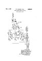
'Now referring to the invention in more detail, the figure illustrates an embodiment of the invention which is used to determine faults in the input-output relationship of a phase detector 10. It receives a rst input 11 from a terminal 12 that may be connected to a radio-frequency source. Another input 13 of phase detector 10 is connected to a second input terminal 14 to recive a similar signal.
The invention uses a tube 17, which includes twoV grids 1S and 19, and may be a type of gated-beam tube, known in the industry as a 6BN6, which serves well because of its amplitude-limiting action and constant cath-ode current characteristics.
A potentiometer 21 is connected between the cathode 22 of tube 17 and ground to bias the tube to a nonconducting condition when grids 18 and 19 are at ground potential, i. e. both grids 18 and 19 are then biased below cut-off.
Input 11 of phase detector 10 .is also provided through a blocking capacitor 23 to a rectification circ-uit 24 which includes diode 26, resistors 27 and 28, and charging capacitor 29. Resistor 28 is connected in series between blocking capacitor 23 and grid 18 of tube 17. Charging capacitor 29 is connected between grid 18 and ground; and resistor 27 is connected between ground and the other side of resistor 28. Diode 26 is connected across resistor 27 and has a polarity which charges capacitor 29 to a positive voltage, that biases grid 1S above cuto when phase-detector input 11 exceeds a minimum amplitude.
The other phase-detector input 13 is further connected through a blocking capacitor 3l to another rectification circuit 32 that comprises -a resistor 33, diode 34 and capacitor 36. Resistor 33 is connected between capacitor 31 and grid 19 of tube 17. Capacitor 36 is connected between grid 19 and ground, and diode 34 is connected across resistor 33 with a polarity that charges capacitor 36 to a positive voltage that is suflicient to bias the other grid 19 above-cut off when phase detector input 13 exceeds a minimum amplitude. If theA amplitude of phase .to attenuate the input signal torectifier l32.-
'and' 'is 'a Its inputis connected to foutput 16 of phase detector 10. lllectiter circuit 41 'includes capacitors 42 and 43 with diodes 44 and 46. Capacitor 42 has another function, since it blocks any direct-voltage output from Vphase detector 10 but passes any A. C. component. Diode 44 is connected serially between capacitor 42 and tap 47 of potentiometer 21, which has a relatively low resistance to ground. Second diode 46 has one end connected to capacitor 42 and has likeseries polarity with respect to lirst diode 44. Second capacitor 43 of the voltage doubler is connected between -ground and the other vend of diode 46. Rectier circuit '41 charges capacitor 43 to a negative direct-voltage which 'has approximately twice the value of the peak amplitude 'of any alternating voltage provided at phase-detector output 16. The time-constants of voltage doubling circuit 41 are long to prevent substantial periodic Vdischarging of its capacitors at its lowest received frequencies.
Another resistor Si is connected serially between diodes 34 and 46; and it eiiectively connects in series the charged 'outputs of rectifier circuits 32 and `41 to form a bridge- `type of circuit 52. YThe D. C. voltage across resistor 33 will be proportional to detector input 13. Consequently, the voltage across capacitor 36 will be the sum of the opponte-polarity voltages across resistor 33 and across capacitor 43. The diterence between these voltages is sensed by grid 19, since Vit is connected across capacitor y There will be very little current iiow within circuit -52 because of the high-impedance components which isolate it from ground'with respect to direct-current flow. Hence, when no charge exists on capacitor 43, the positive charge on capacitor 36 can maintain grid 19 above cuto.
Furthermore, another resistor 53 connects serially between tap 47 and resistor 51. Resistor 53 enables a D. C. connection between tap 47 and grid 19. Accordingly, the setting of tap 47 controls the bias of grid 19. lResistor S3 should have a long time constant with capacitor 36 to prevent its discharge at very low charging frequencies. Resistor 53 also enables a grid-leak for grid 19.
A relay 56 is connected in series between the plate 57 of tube 17 and a B-plus voltage supply. Relay S6 has contacts S which are connected to alarm means (not shown), which might be a light, buzzer, or arrangement for shutting oit equipment or any combination of these, etc.
Any other grids of tube 17 are operably connected. Therefore, accelerator electrode 59 is connected through a resistor `61 to the B-plus source.
In operation, tube 17 is connected to normally conduct when phase-detector is operatingproperly. Accordingly, a fault in the system is indicated by non-conduction of tube 17. Thus, the illustrated embodiment is fail-safe because it will give an alarm indication if a fault develops within itself that interrupts conduction of tube 17.
When phase detector 10 receives phase-locked inputs, its output will be a D. C. voltage, which will be biocked by'capacitor 42. Accordingly, charging capacitor 43 of voltage-doubler rectifying circuit 41 will not be chmged. Then, if phase-detector input 13 is above a minimumrequired value, grid 19 will be biased above cutoii to permit conduction by tube 17. Similarly, if phase-detector input-11 is above a minimum-required value, the other grid 18 will also be biased above'cutoii to allow conduction by tube 17. As a result, tube17'will be in a conductingistate, since this requiresrthat both grids 18 and 19'be simultaneously biased above cutoff.
If either of the two phase-detector inputs 11 or 13 should fail, the positive bias of the respective rectifying circuit 24 or 32 will fail and will go to ground potential, which is below cutoff for their respective grids 18 or 19, because of the cathode bias provided by potentiometer 21. Then, plate-current'conduction will cease. rTherefore, relay 56 will be de-energized, and its contacts S8 will change position to give an alarm or disable the equipment.
Furthermore, if Vthe two phase-detector inputs 11 and 13 remain but are not in phase-lock, an A. C. output is provided from phase-detector 16 which will charge capacitor 43 to a negative voltage that will oppose the positive voltage on capacitor 36 in circuit 52 and drive grid 19 below cutoff, thus interrupting the plate-current and actuating the contacts of Vrelay 52.
Tap 47 of potentiometer 21 is used to adjust the sensitivity of the alarm circuit. It controls the bias between cathode 22 and grid 19 of tube 17. It is preferably set to provide the lowest stable biasing voltage which will bias grid 19 above cutoi when a phase-lock exists between the phase-detector inputs. Then, a minimum amount of amplitude for any A. C. 'component in the phase-detector output will 'cause grid 19 to drop below cutoi and indicate lack of phase-lock.
While a particular form of the invention has been shown and described, it is to be understood that the invention is capable of many modifications. Changes, therefore, in construction and arrangement may be made without departing from the scope of the invention as given by the appended'claims.
What we claim is:
l. Fault detection` means operating with a phase detector having a pair of inputs and an output, comprising electron control means having at least two control electrodes, .rst rectification means having its input connected in series with one of vsaid phase-detector inputs, with theoutput of said first rectitication means connected to one of said control electrodes, second rectification means having its input connected in series with the other of said phase-detector inputs, a third rectification means, means for blocking direct-current and Vfor passing alterhating-current connected between said phase-detector output and the input to saidV third rectification means, with the 'outputs of said second-and third rectification means being opposite polarity voltages, the outputs of said second and third rectification meanseach being serially connected to `the other of said controlelectrodes, with the polaritiesof the outputs of said first, second and third rectification means determining the conductionrstate of said electron control means, whereby a faultV in any of said phase-detector inputs and output changes the conduction state of said electroncontrol means..
2. Fault detection means operating with a phase detector comprising electron control means having a pair of control electrodes, a first rectiiication means having its output connected to one of its control electrodes, means for blocking direct-current and passing alternating-current connected between theV input of said iirst rectification means and one input of said phase detector, second and third rectiication means having oppositepolarity outputs, the outputs of said second and third rectification means connected in common to the other of said control electrodes, second means for blocking direct-current and passing-alternating-current connected between the input of said second rectication means and the other input of said phase detector, and third means for blocking direct-current and passing alternating-current connected between the input to said third rectification means and the output of said phase detector, whereby the conduction state of said electron control means'indi- 5 grids, a first rectifier circuit including a charging capacitor, with its charging capacitor connected to one of said control grids, a first blocking capacitor connected between the input to said first rectiiier circuit and one input of said phase detector, with said first rectification circuit polarized to provide a positive direct-voltage across its charging capacitor for biasing said one control grid above cuto, a second rectifier circuit including another charging capacitor, and a third rectifier circuit including a further charging capacitor, with said another charging capacitor and said further charging capacitor each connected to the other of said grids, a second blocking capacitor connected between the input of said second rectifier circuit and the other input of said phase detector, with said another charging capacitor polarized by said second rectifier circuit with a positive direct-voltage, a third blocking capacitor connected between the input to said third rectifier circuit and the output of said phase detector to'pass any alternating-current output from said phase detector, with said further charging capacitorA polarized by said third rectification circuit with a negative direct-voltage, and alarm means actuated by the nonconduction of said electron tube.
4. Fault detection means used with a phase detector, comprising electron discharge means having at least'two control grids, a potentiometer connected between the cathode of said discharge means and ground, relay means connected serially with the plate of said electron discharge means, a iirst rectifier circuit polarized to provide a positive direct-current output, with its output connected to one of said control grids, a irst blocking capacitor connected between the input of said first rectifier circuit and one input of said phase detector, a second rectifier circuit polarized to provide a positive directvoltage output, with its output connected to the other of said control grids, a second blocking capacitor connected between the input of said second rectiiier circuit and the other input to said phase detector, a third rectifier circuit with its output polarized to provide a negative direct-voltage, a third blocking capacitor connected between the input of said third rectifier circuit and the output of said phase detector, bridge means commonly connecting the outputs of said second and third rectifier circuits to said other control grid, and impedance means connecting the tap of said potentiometer to said other control grid to adjust its bias.
5. Fault detection means used with a phase detector, comprising a gated-beam electron tube having a pair of control grids, relay means connected serially to the plate of said tube, a potentiometer connected between the cathode of said tube and ground, a rst rectifier circuit polarized to provide a positive direct-voltage output, with its output connected to one of said control grids, a blocking capacitor connected between the input of said rst rectifier circuit and one input of said phase detector,
a second rectiiier circuit polarized to provide a positive direct-voltage output, a second blocking capacitor connected between the input of said second rectifier circuit and the other input of said phase detector, a third rectier circuit polarized to provide a negative direct-voltage output, resistor means connecting the outputs of said second and third rectifier circuits to the other of said control grids, a third blocking capacitor connected between the input of said third rectifier circuit and the output of said phase detector, and the tap of said potentiometer connected through said resistor means to said other control grid.
6. Fault detection means used with a phase detector, comprising a gated-beam tube having at least a pair of control grids, a first blocking capacitor having one end connected to one input of said phasedetector; a first rectifier circuit including a first resistor serially connected between the other end of said first blocking capacitor and one of said control grids, a second resistor 'connected between ground and said other end of said rst blocking capacitor, a diode connected across said resistor, and a charging capacitor connected between said one control grid and ground, with said diode polarized to positively charge said charging capacitor; a second blocking capacitor connected on onerside to therother input of said phase detector; a second rectifier circuit comprising a resistor connected between the other side of said second blocking capacitor and the other of said grids, a charging capacitor connected between ground and said other grid, and a diode connected across said resistor with a polarity that obtains a positive directvoltage on said charging capacitor, a third blocking capacitor having one end connected to the output of said phase detector; a voltage-doubling rectifier circuit including irst and second diodes connected with like series polarity, a common point between said diodes connected' to the other side of said third blocking capacitor, a charging capacitor connected between ground and the remaining end of said rst diode, with the remaining end of said second diodes connected to the tap of sai'dl potentiometer, and said diodes polarized to provide a negative direct-voltage on their charging capacitor; a resistor connected between the tap o said potentiometer and the ungnounded side of the charging capacitor in said voltage-doubling rectifier circuit, and another resistor connected between the ungronn'ded end of the charging capacitor in said voltage-doubling rectifier circuit and said other end of said second blocking capacitor, and relay means connected serially to the plate of said tube.
References Cited in the le of this patent UNITED STATES PATENTS
Priority Applications (2)
| Application Number | Priority Date | Filing Date | Title |
|---|---|---|---|
| US598169A US2808564A (en) | 1956-07-16 | 1956-07-16 | Phase detector fault indicator |
| GB14956/57A GB815038A (en) | 1956-07-16 | 1957-05-10 | Phase detector fault indicator |
Applications Claiming Priority (1)
| Application Number | Priority Date | Filing Date | Title |
|---|---|---|---|
| US598169A US2808564A (en) | 1956-07-16 | 1956-07-16 | Phase detector fault indicator |
Publications (1)
| Publication Number | Publication Date |
|---|---|
| US2808564A true US2808564A (en) | 1957-10-01 |
Family
ID=24394518
Family Applications (1)
| Application Number | Title | Priority Date | Filing Date |
|---|---|---|---|
| US598169A Expired - Lifetime US2808564A (en) | 1956-07-16 | 1956-07-16 | Phase detector fault indicator |
Country Status (2)
| Country | Link |
|---|---|
| US (1) | US2808564A (en) |
| GB (1) | GB815038A (en) |
Cited By (3)
| Publication number | Priority date | Publication date | Assignee | Title |
|---|---|---|---|---|
| US3061668A (en) * | 1960-09-09 | 1962-10-30 | Gates Radio Company | Television signal analyzer |
| US3110028A (en) * | 1960-02-10 | 1963-11-05 | Aircraft Radio Corp | Flag control circuit |
| US3128450A (en) * | 1960-01-04 | 1964-04-07 | Litton Industries Inc | Mach number indicating and computing means |
Citations (2)
| Publication number | Priority date | Publication date | Assignee | Title |
|---|---|---|---|---|
| US2522139A (en) * | 1944-10-06 | 1950-09-12 | Curtiss Wright Corp | Frequency responsive system |
| US2613271A (en) * | 1950-04-07 | 1952-10-07 | Rca Corp | Tuning indicator for frequency shift telegraphy |
-
1956
- 1956-07-16 US US598169A patent/US2808564A/en not_active Expired - Lifetime
-
1957
- 1957-05-10 GB GB14956/57A patent/GB815038A/en not_active Expired
Patent Citations (2)
| Publication number | Priority date | Publication date | Assignee | Title |
|---|---|---|---|---|
| US2522139A (en) * | 1944-10-06 | 1950-09-12 | Curtiss Wright Corp | Frequency responsive system |
| US2613271A (en) * | 1950-04-07 | 1952-10-07 | Rca Corp | Tuning indicator for frequency shift telegraphy |
Cited By (3)
| Publication number | Priority date | Publication date | Assignee | Title |
|---|---|---|---|---|
| US3128450A (en) * | 1960-01-04 | 1964-04-07 | Litton Industries Inc | Mach number indicating and computing means |
| US3110028A (en) * | 1960-02-10 | 1963-11-05 | Aircraft Radio Corp | Flag control circuit |
| US3061668A (en) * | 1960-09-09 | 1962-10-30 | Gates Radio Company | Television signal analyzer |
Also Published As
| Publication number | Publication date |
|---|---|
| GB815038A (en) | 1959-06-17 |
Similar Documents
| Publication | Publication Date | Title |
|---|---|---|
| US2112826A (en) | Alarm system | |
| US3641546A (en) | High-low voltage level sensor | |
| US4138232A (en) | Detector for detecting voltage breakdowns on the high-voltage side of an electric precipitator | |
| US3749944A (en) | Undervoltage sensing circuit | |
| US3243796A (en) | Three-phase voltage unbalance detector | |
| US2113220A (en) | Rectifier system | |
| US2433350A (en) | Superheterodyne radio receiver having compensating means for frequency drift of the received carrier wave | |
| US2228367A (en) | Frequency meter | |
| US2993172A (en) | Voltage unbalance detector apparatus | |
| US3069558A (en) | Frequency sensitive control circuit | |
| US2808564A (en) | Phase detector fault indicator | |
| US2640939A (en) | Phase detector | |
| US2343263A (en) | Carrier-signal frequency detector | |
| US2952811A (en) | Modulation synchronizing pulse generator | |
| US4567539A (en) | Power interruption and brownout detector | |
| US2915631A (en) | Self-tuning fm detector circuit | |
| US2577475A (en) | Trigger operated pulse amplitude selector | |
| US3026505A (en) | Unijunction transistor oscillator voltage monitoring circuit | |
| US5315186A (en) | Frequency and phase lock detector | |
| US2312306A (en) | Indicator or relay system | |
| US3275940A (en) | Automatic frequency control means for single-sideband receivers and the like | |
| US2922109A (en) | Electric phase discriminator | |
| US2659850A (en) | Motor control system and the like | |
| US2911545A (en) | Semiconductor apparatus | |
| US2439872A (en) | Frequency responsive circuits |