US2794271A - Throw wheel for snow removers - Google Patents
Throw wheel for snow removers Download PDFInfo
- Publication number
- US2794271A US2794271A US199741A US19974150A US2794271A US 2794271 A US2794271 A US 2794271A US 199741 A US199741 A US 199741A US 19974150 A US19974150 A US 19974150A US 2794271 A US2794271 A US 2794271A
- Authority
- US
- United States
- Prior art keywords
- throw
- wheel
- blades
- snow
- hub
- Prior art date
- Legal status (The legal status is an assumption and is not a legal conclusion. Google has not performed a legal analysis and makes no representation as to the accuracy of the status listed.)
- Expired - Lifetime
Links
- 230000033001 locomotion Effects 0.000 description 4
- 230000004048 modification Effects 0.000 description 4
- 238000012986 modification Methods 0.000 description 4
- 230000035508 accumulation Effects 0.000 description 2
- 238000009825 accumulation Methods 0.000 description 2
- 230000005540 biological transmission Effects 0.000 description 2
- 101150034533 ATIC gene Proteins 0.000 description 1
- 241000209140 Triticum Species 0.000 description 1
- 235000021307 Triticum Nutrition 0.000 description 1
- 229960001948 caffeine Drugs 0.000 description 1
- 238000010276 construction Methods 0.000 description 1
- 238000010586 diagram Methods 0.000 description 1
- 238000009434 installation Methods 0.000 description 1
- 239000004576 sand Substances 0.000 description 1
- PHWXUGHIIBDVKD-UHFFFAOYSA-N sitaxentan Chemical compound CC1=NOC(NS(=O)(=O)C2=C(SC=C2)C(=O)CC=2C(=CC=3OCOC=3C=2)C)=C1Cl PHWXUGHIIBDVKD-UHFFFAOYSA-N 0.000 description 1
- 229960002578 sitaxentan Drugs 0.000 description 1
- RYYVLZVUVIJVGH-UHFFFAOYSA-N trimethylxanthine Natural products CN1C(=O)N(C)C(=O)C2=C1N=CN2C RYYVLZVUVIJVGH-UHFFFAOYSA-N 0.000 description 1
Images

Classifications
-
- E—FIXED CONSTRUCTIONS
- E01—CONSTRUCTION OF ROADS, RAILWAYS, OR BRIDGES
- E01H—STREET CLEANING; CLEANING OF PERMANENT WAYS; CLEANING BEACHES; DISPERSING OR PREVENTING FOG IN GENERAL CLEANING STREET OR RAILWAY FURNITURE OR TUNNEL WALLS
- E01H5/00—Removing snow or ice from roads or like surfaces; Grading or roughening snow or ice
- E01H5/04—Apparatus propelled by animal or engine power; Apparatus propelled by hand with driven dislodging or conveying levelling elements, conveying pneumatically for the dislodged material
- E01H5/08—Apparatus propelled by animal or engine power; Apparatus propelled by hand with driven dislodging or conveying levelling elements, conveying pneumatically for the dislodged material dislodging essentially by driven elements
- E01H5/09—Apparatus propelled by animal or engine power; Apparatus propelled by hand with driven dislodging or conveying levelling elements, conveying pneumatically for the dislodged material dislodging essentially by driven elements the elements being rotary or moving along a closed circular path, e.g. rotary cutter, digging wheels
- E01H5/098—Apparatus propelled by animal or engine power; Apparatus propelled by hand with driven dislodging or conveying levelling elements, conveying pneumatically for the dislodged material dislodging essentially by driven elements the elements being rotary or moving along a closed circular path, e.g. rotary cutter, digging wheels about horizontal or substantially horizontal axises perpendicular or substantially perpendicular to the direction of clearing
Definitions
- the blade carrier has a toroidalsurfa'ce portion to'which the tapering surface portion of the' carrier is tangential and whichadjoinshthe base. of the carrier'.
- the blade carrier has a toroidalsurfa'ce portion to'which the tapering surface portion of the' carrier is tangential and whichadjoinshthe base. of the carrier'.
- thein'n'er edge sections of the-blades which, face-toward the direction olfsnow admission 'are curved inwardly so as to join the blade carriera short distance below the apex ofthe, carrier, the outer portion ofthe blades ⁇ thus standing free.
- a suitable carrier for the throw blades may comprise a cone surface portion, or a conoid surface portion, thatis, a surface portion the describing lineof which, instead of beingl a straight line, is curved.
- the blades may have Vany suitable form.
- the throw portions of the bladesf may consist,I as Yis known per se, of sections othollow cylinders theY describing lines of which are parallel tothe base of the'blade carrier.
- the most rearward portions of the surface ot the blades, in the direction of rotation leadl the throw wheel radius with which they are parallel by a predetermined eccentricity in the direction of'r-.ot'ation
- Other blade types may be also used.
- the throw blades may comprise Va guide portion consisting otahelical surface the describing'lihe of which is substantially parallel to the base plane of the blade carrier, and la throw portion adjoining the guide portion and consisting ⁇ of a half cylinder or. of a half frustum of a cone. ln each vcase the 11e-entering spaces behind the blades are suitably covered, either by special covering surfaces or by an arrangement such that two adjacent bladespartially overlap.
- Figure 1 is an overall side view, partly in section, showing a snow remover embodying features of the invention
- Figure 2 is an overall top plan view, withgpartsf-removed, ofthe snow-remover ofVv Fig. 1, as-seen approximately along-the line Z-Zg l Figuref3fis-an enlarged-front view ofthe snow 'remover shown in-Figs. l and 2;
- Figure 5 is a front view showing an embodiment ot the throw wheelheving threecylindrical blades
- Figure 6 is-asimilar' fr'o'nt -view showing a throw wheel having six cylindrical blades
- Figures 7 and ⁇ 8 are cross sectional views of the'blades ofthe throw wheels shown in' Figures Sand 6, respectively.
- Figuref9* is a cen-tralsectional view taken approximately along'fthe-lines 9-9 of Figs. 5 and 6',
- FigureslO and l1 are diagrammatic views showing the unwound cylinder describedaround the throw wheel and indicating the form ot'thefthrow-blades shown in Figures 5 and'6,.respectively;
- Figure-l4 isa central seetionatview taken approximately along thelin'e 11i-'#14 of Figure 12;
- Figure l5 isa sim-lar vcentral sectional view taken as proximately al'ongthe line 15-1115 ot' Figure 13;
- Figurey 116 is atdiagramm'atic View showing the unwound cylinder descrtbedraround the'throw' wheel and indicating the-"formfot the throw-blades shownin'.
- Figure t7' isfasimilar diagrammatic' view of' the-blades offFig. 13;. Y
- Figure 18 is a perspective view ofthe throw' wheel shown inFig. 61.
- Figure 129 isa similar perspective view of the throw wheel of Fig; 13..'
- Two lateralr'horiontal longitudinal girder'sl 10 are secured to the two'vuprights*9 ⁇ and'interconnectedattheir front ends by a front-cross bearer11.
- Uprights 12 protrude somewhat downwardly at the lends of the longitudinal girders ltlandi'the cross bearer' 11'an'd inl the A'center of the vvehicl'e'the crossfbearers 11v and 7 are' interconnected by a central longitudinalgirder 1:3.
- Short uprights 1'4 andi 15i ⁇ extend downwardly,frespectivelytrom 'the' junction points of the members -111 V"and: ⁇ 113", an'd 7'and 13.
- the endless 'track' drive yis provided on the vehicle trame, the-endless track'chains 16' running'over two" chain wheelsl I7 and 17a, andp'rollers 18'.
- the output shaft 23 of the transmission 22 is journall'ed in' the vehicle Ifrarnefbyrneans of bearings 24 and 25 and 'carries a1b'evel'gear'26 which meshes with a bevel gear V27.
- the latter isY secured vto ahori'zontal shaft v2S which is journalled in two endl bearings' 30' and a central bearing 29 andextends transversely of thelon'gitudinal axis ofL the vehicle,A Laterally ofthe central plane of the.
- the shaftv 28 carries two snow' removal cylinders 31.
- Each snow removal cylinder comprises two end--'anges 32 whichcarry at.
- the anges 32 also carry a central core member 35 and three guide blades 34 which are pivotally connected to the core member 35 at 36, the core members 35 are rotatably adjustable relatively to the shaft 28.
- Each snow removal cylinder 31 is surrounded fr'om below by a casing 37 and from above by 'a casing 33, the latter having a guide surface 39. These casings communicate with the casing which surrounds the throw wheels through an admission opening 6l, to be described in more detail below.
- the snow removal cylinders convey the snow from the bottom to the top as a result of the direction of rotation indicated by the arro
- a separate motor 40 also mounted on the Vehicle frame, is provided for driving the two throw wheels mounted behind the snow removal cylinders 31.
- the throw wheels could be driven by the vehicle motor 19 by means of a separate gearing.
- the motor 40 for driving the throw wheels comprises a shaft 41 journalled in a bearing 42 and carl and 46. At each end the bevel gear 48 in meshing engagement with a bevel gear ⁇ 49 on a shaft Sii which is journalled in bearings 51 and 52.
- the main component of the throw wheel is a throw wheel cone 58 having a radius R and serving as a carrier for the throw wheel blades.
- the apex 64 of the throw wheel cone 5S faces toward the direction s in which the cut-off snow is admitted.
- the shaft 54 has at its front end a thread 65 and behind this thread a square portion 66.
- the apex portion 64 of the cone 58 has a female thread 68, which is engaged with the thread 65.
- the throw wheels may have blades of different forms.
- the blades In the embodiments shown in Figures 5 to l1 the blades have the form of sections of hollow cylinders.
- the axes C of the hollow cylinders are half the height of the throw wheel, when considered inclusively of its apex portion 64.
- the portions of the several blades which adjoin the throw wheel are firmly joined to the throw wheel portions 69, 7i), 71, whereas their arcuate portion, facing the side on which ,the snow is admitted, and the portion adjoining the theoretical circumference of the snow wheel cylinder, stand free.
- the limiting edges of the throw blades S5? stand free from o, along the arc having the radius r3 to n, and from o to u, whereas they are firmly joined to the throw wheel from n, along the arc having the radius r1, to u.
- cylindrical cover surfaces 72 which are curved in the opposite direction may be provided, as shown in Figures 5, 6, l0 and 1l, for covering up the re-entering dead spaces 7?.
- cover surfaces of other suitable shape may be provided, Seen from the front ( Figure 5) the leading corner o and the rear corner u of each blade 59 lie in a line perpendicular to the base of the throw wheel 58,
- Figure 10 showing the unwound cylinder described 4around the throw wheel, indicates the direction of rotation D of the throw wheel, the direction of admission s of the snow cut loose and admitted to the throw wheel, the 4form of the throw blades 59 yfrom o to u, the radius r2 of the throw blades, the cover surfaces 72 to be provided adjoining the throw blades 59, and the re-enten'ng spaces 73 covered up by the cover surfaces.
- Figure ll a diagram showing the unwound cylinder described around the throw wheel.
- the blades 59 consist of guide portions 74 and adjoining throw portions 75.
- the guide portions 74 consist of helical surfaces the describing lines of which are substantially parallel to the base plane of the blade carrier 59 whereas the throw portions have the shape of hollow half cylinders.
- the throw portions may also be shaped as half frustums of cones. In this modification the describing lines of the guide portions 74 pass through the axis A-A of the throw wheel, the outside of which has the radius R, and are parallel to the base plane u-u of the throw wheel.
- each throw blade 59 has a guide portion 74, which begins at o and comprises a helical surface, the describing line of which passes through the axis A-A of the throw wheel and is parallel to the base plane u-u of the throw wheel, and a cylindrically curved throw portion 75 adjoining guide portion 74.
- the surface portion i of the blades, facing the side on which the snow is admitted, is identical for each two adjacent blades 59, which do not separate until the point a is reached and at which the throw portion, having a curvature of theradius r2, adjoins.
- the re-entering spaces 73 at the back of the throw portions are covered by the guide portion of the next following throw blade, 12, the leading corner o of each throw blade 59 and the rear corner u of the next preceding throw blade 59, which edge adjoins the base of the carrier, lie on a line perpendicular to the base yof the throw wheel.
- the most rearward part m of the cylindrical throw portion 75 in the direction of rotation is covered by lche helical guide portion of the next following throw blade 59.
- FIGmatic view of Figure 16 showing the unwound cylinder described around the throw wheel indicates as in Figures yand ll, the direction of rotation D of the throw wheel, the direction of admission s of the snow, the form of the throw blades 59 with the guide portions 74 and the throw portions 75, and the covered-up re-entering spaces 73.
- the size of these reentering spaces is reduced as the number of throw blades 59 on the wheel is increased.
- Throw wheels of other forms may be conceived, within the scope of this invention, which are suitable for fulfilling the requirements set forth hereinbefore.
- the throw portions may have the shape of a half frustum of a cone.
- the guide surfaces may constitute helical surfaces the describing line of which is inclined to the axis of the throw wheel cone.
- the essential feature is the taper of the blade carrier, and the construction of the carrier and of the blades so that the snow admitted vto the wheel is not subjected to directional changes caused by impact.
- arcuate which is used generically to define the shape of the throw blades, includes the term half frustum of a cone and the term half cylinder.
- a throw wheel for a snow plow adapted to receive and throw the snow directed inwardly toward it from the front of the plow, comprising a conical hub adapted to be rotatably mounted on an axis with its apex in opposition to the direction of inward movement of the snow, and a plurality of separate uniformly-dimensioned arcuate throw blades extending outwardly from said hub, said hub having a conical surface portion extending from the apex substantially to the base portion of the hub and a toroidal surface portion merging with said conical surface portion substantially only at said base portion, said conical surface portion being the predominant portion of said hub, all of said throw blades being connected to said hub along said conical surface portion and along said toroidal surface portion merging with said conical surface portion, and portions of the free edges of all of said throw blades extending outwardly toward said apex beyond the outermost point of connection to said conical surface portion.
- a ythrow wheel for a snow plow adapted to receive and throw the snow directed inwardly toward it from the front of the plow, comprising a conical hub adapted to be rotatively mounted on an axis with its apex in opposition to the direction of inward movement of the snow, and arcuate throw blades extending outwardly from said hub, said hub having a conical surface extending from the ⁇ apex substantially to the base of the hub and a toroidal surface merging with said conical surface substantially only at said base, and'said throw blades comprise guide portions having helical surfaces, the describing line of which is substantially parallel to the base of the conical hub, and adjoining throw portions having surfaces corresponding to the lexternal surfaces of axially bi-sected conical frustums.
- a throw wheel adapted to receive and throw said snow, said throw wheel comprising a conical .hub rotatably mounted in said plow with its apex in opposition to the direction of inward movement of the snow and arcuate throw blades extending outwardly from said hub, said hub having a conical surface portion extending from the apex substantially to the base portion of the hub and a toroidal surface portion merging with said conical surface portion substantially only at said base portion, said conical surface p0rtion being the predominant portion of said hub, all o Said throw blades being connected to said hub along said conical surface portion and along said toroidal surface portion merging with said conical surface portion, and portions of the free edges of all of said throw blades extending outwardly toward said apex beyond the outermost point of connection to said conical surface portion.
Landscapes
- Engineering & Computer Science (AREA)
- Architecture (AREA)
- Civil Engineering (AREA)
- Structural Engineering (AREA)
- Road Repair (AREA)
Description
June 4, 1957 F. F. wvALLAcK THROW FOR SNOW REMOVERS Filed Decl 8. 1950 1N VEN TOR Fran Z E Wd //'f/f By June 4, 1957 F, F WALLACK 2,794,271
THROW WHEEL FOR SNOW REMOVERS Filed Dec. 8. 1950 5 Sne'etsf-Sheet 2 June 4, 1957 I F. F. wALLAcK THROW WHEEL FOR snow REMovERs Filed Dec. 8.A 1950 INVENToR. Fra/71 E Wd //a/f Arran/Vf Y June 4, 1.957 F. F. wALLAcK 2,794,271
THROW WHEEL FOR SNOW REMOVERS Filed Dec. 8. 1950 5 Sneets-Sheet 4 June 4, 1957 F. F. wALLAcK 2,794,271
THROW WHEEL FOR SNOW REMOVERS Filed Dec. 8. 1950 5 Smeets-Sheet 5 INVENTOR. FRANZ F. VVALLACK ATTORNEY United States Patent 2,794,271 runow vwaaier FOR sNow REMovERs FrauzrF. Wallack, Bruck an der Glocknerstrasse, Austria, assigner to GrossglocknerLl-Iochalpenstrassen Aktiengesellschaft, Salzburg, Austria, acorpo'r tion of 'Austria Application December 8,1950, Serial No. 199,741 Claims priority, application VAustriaDeceinluar'i, 1949 9 Claims. (Cl.` S7-43) This invention relates to centrifugal snow removcrs which comprise means for cutting the `snow and conveying it to throw wheels which rotate and cause the snow to be hurled out through an opening in the throwrwheel casing. In snow removers of this type the throw wheel comprises a plurality of throw blades tixed to a carrier which conbody which-1s rotatable Within a stationary cylindrical the throw wheel casing. The vapex of the blade carrier faces against the direction in which the snow is admitted into the drum.
it is an object of the invention to provide a throw `wheel of the. type described which is designed for improved efficiency so that the snow handled by the-wheel does notl undergo directional changes causedv by impact.
Other objects of this invention will become apparent as the speciiication proceeds.
One feature of this invention resides in the fact that the blade carrier has a toroidalsurfa'ce portion to'which the tapering surface portion of the' carrier is tangential and whichadjoinshthe base. of the carrier'. 'Preferably there is only a small clearance between the outer'ed'ges of the, blades and the drum, vwhereas thein'n'er edge sections of the-blades which, face-toward the direction olfsnow admission 'are curved inwardly so as to join the blade carriera short distance below the apex ofthe, carrier, the outer portion ofthe blades `thus standing free. Toprovide for ready installation and removal of the throw wheel, its apex portion may be screwed into place. A suitable carrier for the throw blades may comprise a cone surface portion, or a conoid surface portion, thatis, a surface portion the describing lineof which, instead of beingl a straight line, is curved.
The blades may have Vany suitable form. Advantageously, the throw portions of the bladesfmay consist,I as Yis known per se, of sections othollow cylinders theY describing lines of which are parallel tothe base of the'blade carrier. Accordingv to the invention the most rearward portions of the surface ot the blades, in the direction of rotation leadl the throw wheel radius with which they are parallel by a predetermined eccentricity in the direction of'r-.ot'ation Other blade types, however, may be also used. For instance, the throw blades may comprise Va guide portion consisting otahelical surface the describing'lihe of which is substantially parallel to the base plane of the blade carrier, and la throw portion adjoining the guide portion and consisting` of a half cylinder or. of a half frustum of a cone. ln each vcase the 11e-entering spaces behind the blades are suitably covered, either by special covering surfaces or by an arrangement such that two adjacent bladespartially overlap.
By the use ofKV a throw wheel havingthe above-described structural characteristics of the invention, all losses of power vwhich woul-'d otherwise occur as a result of directional changes of the snow caused by impact are avoided, and the efficiency of the snow remover is substantially improved.
ln the accompanying drawings several embodimentsvof the invention are shown by way of example.
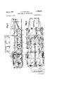
Figure 1 is an overall side view, partly in section, showing a snow remover embodying features of the invention;
Figure 2 is an overall top plan view, withgpartsf-removed, ofthe snow-remover ofVv Fig. 1, as-seen approximately along-the line Z-Zg l Figuref3fis-an enlarged-front view ofthe snow 'remover shown in-Figs. l and 2;
Figure `4Yis san-enlarged sectional view taken approximatelyv along a vertical plane passingthrough the center of a throw wheel approximately along the line 4-4 in Fig. 2,. showing thesnowfr'enovalcylinder in association `with thethrow wheel',
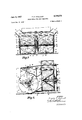
Figure 5 is a front view showing an embodiment ot the throw wheelheving threecylindrical blades;
Figure 6 is-asimilar' fr'o'nt -view showing a throw wheel having six cylindrical blades;
Figures 7 and`8=are cross sectional views of the'blades ofthe throw wheels shown in' Figures Sand 6, respectively.
Figuref9* is a cen-tralsectional view taken approximately along'fthe-lines 9-9 of Figs. 5 and 6',
FigureslO and l1 are diagrammatic views showing the unwound cylinder describedaround the throw wheel and indicating the form ot'thefthrow-blades shown in Figures 5 and'6,.respectively;
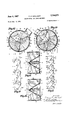
havingthree and sixlielical blades, respectively;
Figure-l4 isa central seetionatview taken approximately along thelin'e 11i-'#14 of Figure 12;
.Figure l5 isa sim-lar vcentral sectional view taken as proximately al'ongthe line 15-1115 ot'Figure 13;
Figurey 116: is atdiagramm'atic View showing the unwound cylinder descrtbedraround the'throw' wheel and indicating the-"formfot the throw-blades shownin'. Figure 12';
Figure t7' isfasimilar diagrammatic' view of' the-blades offFig. 13;. Y
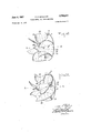
Figure 18 is a perspective view ofthe throw' wheel shown inFig. 61; and
Figure 129" isa similar perspective view of the throw wheel of Fig; 13..'
Inthe embodiment shownfin Figs. 1 to y3, the snow remover 4is mounted. on the framey of an endless vtrack type driven vehicle. 'Thefframe of: the vehicle comprisesv two upper longitudinal girdersy 1 andltwo longitudinalfgirders 2 which are obliquely inclined downwardly in front. Longitudinal girders Y:1 and' Z. are interconnected by cross bearersy 3, 4; 5',v 6,171and `8. Uprights'9, upwardlyfprotrudng soniewliatover theA l'ongitwdinalv girders 11,:are secured'f'toY theftronty ends ofthe longitudinal 'girders' Y1. Two lateralr'horiontal longitudinal girder'sl 10 are secured to the two'vuprights*9` and'interconnectedattheir front ends by a front-cross bearer11. Uprights 12 protrude somewhat downwardly at the lends of the longitudinal girders ltlandi'the cross bearer' 11'an'd inl the A'center of the vvehicl'e'the crossfbearers 11v and 7 are' interconnected by a central longitudinalgirder 1:3. Short uprights 1'4 andi 15i` extend downwardly,frespectivelytrom 'the' junction points of the members -111 V"and: `113", an'd 7'and 13.
The endless 'track' drive yis provided on the vehicle trame, the-endless track'chains 16' running'over two" chain wheelsl I7= and 17a, andp'rollers 18'. The motor 19/for drivingtheyehiCIe'is-mounted' on the frame andi drives, by means of geari'ngzt),` the rear wheels 17al forthe'endl'ess track chains. A shaft v21tlead's from the 'gearing 20 tota t-ransmission'zz. The output shaft 23 of the transmission 22 is journall'ed in' the vehicle Ifrarnefbyrneans of bearings 24 and 25 and 'carries a1b'evel'gear'26 which meshes with a bevel gear V27. The latter isY secured vto ahori'zontal shaft v2S which is journalled in two endl bearings' 30' and a central bearing 29 andextends transversely of thelon'gitudinal axis ofL the vehicle,A Laterally ofthe central plane of the. vehicle the shaftv 28 carries two snow' removal cylinders 31. Each snow removal cylinder comprises two end--'anges 32 whichcarry at. their perimetersi three plowv sharesidor; plowing ot the -snow when -the-r snow removal cylinder rotates. The anges 32 also carry a central core member 35 and three guide blades 34 which are pivotally connected to the core member 35 at 36, the core members 35 are rotatably adjustable relatively to the shaft 28. Each snow removal cylinder 31 is surrounded fr'om below by a casing 37 and from above by 'a casing 33, the latter having a guide surface 39. These casings communicate with the casing which surrounds the throw wheels through an admission opening 6l, to be described in more detail below. In the embodiment shown, the snow removal cylinders convey the snow from the bottom to the top as a result of the direction of rotation indicated by the arro In the embodiment illustrated, a separate motor 40, also mounted on the Vehicle frame, is provided for driving the two throw wheels mounted behind the snow removal cylinders 31. However, the throw wheels could be driven by the vehicle motor 19 by means of a separate gearing. The motor 40 for driving the throw wheels comprises a shaft 41 journalled in a bearing 42 and carl and 46. At each end the bevel gear 48 in meshing engagement with a bevel gear `49 on a shaft Sii which is journalled in bearings 51 and 52. The shaft 5t) is connected with a transmission 53, the output shaft S4 bearings 5S and 56 in the vehicle frame and carries at its front end a throw wheel 57. In all embodiments throw wheel 57 comprises a cone S3 which is secured on the shaft 54 and carries blades 59. Each of the two throw wheels is surrounded by a casing 60 which communicates, through an admission opening 61, with the casing 37, 38 of the snow removal cylinders, and each casing 6@ has a discharge passage 62.
The main component of the throw wheel is a throw wheel cone 58 having a radius R and serving as a carrier for the throw wheel blades. The apex 64 of the throw wheel cone 5S faces toward the direction s in which the cut-off snow is admitted. The shaft 54 has at its front end a thread 65 and behind this thread a square portion 66. The apex portion 64 of the cone 58 has a female thread 68, which is engaged with the thread 65. The
of which is journalled by means of j whereas the center line m of the throw wheel, and of throwing the snow, in a substantially radial direction, out of the cylindrical casing ydrum 6i) surrounding the throw wheel through the opening 62 provided in the casing. Y
To full this function the throw wheels may have blades of different forms. In the embodiments shown in Figures 5 to l1 the blades have the form of sections of hollow cylinders. The describing lines of the throw blades 59, curved according to a hollow cylinder having the radius r2, are parallel to the throw wheel radius R with which they are associated, and lead in advance of said radius in the direction of rotation by the eccentricity E. The axes C of the hollow cylinders are half the height of the throw wheel, when considered inclusively of its apex portion 64. As mentioned above, the portions of the several blades which adjoin the throw wheel are firmly joined to the throw wheel portions 69, 7i), 71, whereas their arcuate portion, facing the side on which ,the snow is admitted, and the portion adjoining the theoretical circumference of the snow wheel cylinder, stand free. Hence, the limiting edges of the throw blades S5? stand free from o, along the arc having the radius r3 to n, and from o to u, whereas they are firmly joined to the throw wheel from n, along the arc having the radius r1, to u.
To prevent a whirling motion of air or undesirable accumulations of snow at the back of the throw blades 59, cylindrical cover surfaces 72 which are curved in the opposite direction may be provided, as shown in Figures 5, 6, l0 and 1l, for covering up the re-entering dead spaces 7?. Instead of these oppositely curved cylindrical cover surfaces, cover surfaces of other suitable shape may be provided, Seen from the front (Figure 5) the leading corner o and the rear corner u of each blade 59 lie in a line perpendicular to the base of the throw wheel 58,
the throw blade lags behind in the direction of rotation of the throw wheel and is spaced from the axis A-A by the eccentricity E. Figure 10, showing the unwound cylinder described 4around the throw wheel, indicates the direction of rotation D of the throw wheel, the direction of admission s of the snow cut loose and admitted to the throw wheel, the 4form of the throw blades 59 yfrom o to u, the radius r2 of the throw blades, the cover surfaces 72 to be provided adjoining the throw blades 59, and the re-enten'ng spaces 73 covered up by the cover surfaces. The sectional views taken at right angles to the describing lines of the hollow cylinders (Figure 7) show the continuous curvature of the throw blades 59 from their upper end o through the central point m to the lower end u, with the radius r2, and the direction of rotation D of the throw wheel.
The embodiment of the throw wheel shown in Figures 6, 8, and 11 differs from that shown in Figures 5, 7, and
a central section and Figure ll a diagram showing the unwound cylinder described around the throw wheel.
In the embodiment shown in Figures l2, 14, and 16 the blades 59 consist of guide portions 74 and adjoining throw portions 75. The guide portions 74 consist of helical surfaces the describing lines of which are substantially parallel to the base plane of the blade carrier 59 whereas the throw portions have the shape of hollow half cylinders. The throw portions, however, may also be shaped as half frustums of cones. In this modification the describing lines of the guide portions 74 pass through the axis A-A of the throw wheel, the outside of which has the radius R, and are parallel to the base plane u-u of the throw wheel. The edge section of the several throw wheel blades 59 adjoining the throw wheel is firmly joined to the latter whereas their arcuate edge section, facing the side on which the snow is thrown in, and the edge section adjoining the theoretical cylinder circumference, stand free. Hence, there are in this modification, as in that shown in Figures -to 11, blade edge sections which stand free, and blade edge sections joined to the throw wheel. In the modification shown in Figures 12, 14, and 16, however, the radius r3 of the curvature of the forward inner edge of the blades varies with the number of throw blades provided on the throw wheel.
The diagrammatic view showing the unwound cylinder described around the throw wheel (Figure 16) shows `that each throw blade 59 has a guide portion 74, which begins at o and comprises a helical surface, the describing line of which passes through the axis A-A of the throw wheel and is parallel to the base plane u-u of the throw wheel, and a cylindrically curved throw portion 75 adjoining guide portion 74. The surface portion i of the blades, facing the side on which the snow is admitted, is identical for each two adjacent blades 59, which do not separate until the point a is reached and at which the throw portion, having a curvature of theradius r2, adjoins. The re-entering spaces 73 at the back of the throw portions are covered by the guide portion of the next following throw blade, 12, the leading corner o of each throw blade 59 and the rear corner u of the next preceding throw blade 59, which edge adjoins the base of the carrier, lie on a line perpendicular to the base yof the throw wheel. On the other hand, the most rearward part m of the cylindrical throw portion 75 in the direction of rotation is covered by lche helical guide portion of the next following throw blade 59. The diagrammatic view of Figure 16 showing the unwound cylinder described around the throw wheel, indicates as in Figures yand ll, the direction of rotation D of the throw wheel, the direction of admission s of the snow, the form of the throw blades 59 with the guide portions 74 and the throw portions 75, and the covered-up re-entering spaces 73. The size of these reentering spaces is reduced as the number of throw blades 59 on the wheel is increased.
The modification of the throw wheel shown in Figures 13, 15, and 17 differs from that shown in Figures 12, 14, and 16 only in that each throw wheel carries six throw blades 59 instead of three.
Throw wheels of other forms may be conceived, within the scope of this invention, which are suitable for fulfilling the requirements set forth hereinbefore. As has been mentioned hereinbefore, the throw portions may have the shape of a half frustum of a cone. The guide surfaces may constitute helical surfaces the describing line of which is inclined to the axis of the throw wheel cone. The essential feature is the taper of the blade carrier, and the construction of the carrier and of the blades so that the snow admitted vto the wheel is not subjected to directional changes caused by impact.
In the appended claims, the term arcuate, which is used generically to define the shape of the throw blades, includes the term half frustum of a cone and the term half cylinder.
What I claim is:
1. A throw wheel for a snow plow adapted to receive and throw the snow directed inwardly toward it from the front of the plow, comprising a conical hub adapted to be rotatably mounted on an axis with its apex in opposition to the direction of inward movement of the snow, and a plurality of separate uniformly-dimensioned arcuate throw blades extending outwardly from said hub, said hub having a conical surface portion extending from the apex substantially to the base portion of the hub and a toroidal surface portion merging with said conical surface portion substantially only at said base portion, said conical surface portion being the predominant portion of said hub, all of said throw blades being connected to said hub along said conical surface portion and along said toroidal surface portion merging with said conical surface portion, and portions of the free edges of all of said throw blades extending outwardly toward said apex beyond the outermost point of connection to said conical surface portion.
In the front View of Figure` 2. A throw wheel as deiined in claim 1, wherein the forward edges of said throw blades are arcuate in form and curve radially inwardly toward the hub, whereby said forward edges merge with the hub at a point which is spaced axially of the hub from the outermost point of said edges.
3. A throw wheel as dened in claim 1, wherein the throw blades are in the form of sections of hollow cylinders having a surface parallel to the base of the conical hub, and the blades are mounted on the hub in such manner that the portions of the surfaces of the cylinders which are rearwardmost in the direction of rotation of the hub are parallel to the radius of the hub but are offset therefrom by a predetermined eccentricity in the direction of rotation of the hub.
4. A throw wheel as dened in claim 3, wherein ythe axes of said cylinder sections intersect the surface of the hub at a point approximately at half the height of the hub.
5. A throw wheel as dened in claim 3, wherein the rear portions of the blades in the direction of rotation are shielded by means providing a deecting surface for preventing accumulation of snow thereagainst.
6. A throw wheel `as defined in claim 5, wherein the means defining the deecting surface comprise members having cylindrical surfaces having a curvature opposite to that of the throw blades.
7. A ythrow wheel for a snow plow adapted to receive and throw the snow directed inwardly toward it from the front of the plow, comprising a conical hub adapted to be rotatively mounted on an axis with its apex in opposition to the direction of inward movement of the snow, and arcuate throw blades extending outwardly from said hub, said hub having a conical surface extending from the `apex substantially to the base of the hub and a toroidal surface merging with said conical surface substantially only at said base, and'said throw blades comprise guide portions having helical surfaces, the describing line of which is substantially parallel to the base of the conical hub, and adjoining throw portions having surfaces corresponding to the lexternal surfaces of axially bi-sected conical frustums.
8. A throw wheel as defined in claim 7, wherein the guide portion and the throw portion of each blade are united at their ends adjacent the apex of the hub.
9. In a snow plow having means for engaging the snow and directing it inwardly of the plow, a throw wheel adapted to receive and throw said snow, said throw wheel comprising a conical .hub rotatably mounted in said plow with its apex in opposition to the direction of inward movement of the snow and arcuate throw blades extending outwardly from said hub, said hub having a conical surface portion extending from the apex substantially to the base portion of the hub and a toroidal surface portion merging with said conical surface portion substantially only at said base portion, said conical surface p0rtion being the predominant portion of said hub, all o Said throw blades being connected to said hub along said conical surface portion and along said toroidal surface portion merging with said conical surface portion, and portions of the free edges of all of said throw blades extending outwardly toward said apex beyond the outermost point of connection to said conical surface portion.
References Cited in the tile of this patent UNITED STATES PATENTS 395,548 Corbett Ian. 1, 1889 443,247 Wheat Dec. 23, 1890 1,037,659 Rembert Sept. 3, 1912 1,528,969 Edwards Mar. 10, 1925 2,375,981 Ellis May 15, 1945 FOREIGN PATENTS 72,873 Germany Jan. 6, 1894 369,079 Germany Feb. 14, 1923 1,688 Great Britain of 1909
Applications Claiming Priority (1)
| Application Number | Priority Date | Filing Date | Title |
|---|---|---|---|
| AT2794271X | 1949-12-09 |
Publications (1)
| Publication Number | Publication Date |
|---|---|
| US2794271A true US2794271A (en) | 1957-06-04 |
Family
ID=3690425
Family Applications (1)
| Application Number | Title | Priority Date | Filing Date |
|---|---|---|---|
| US199741A Expired - Lifetime US2794271A (en) | 1949-12-09 | 1950-12-08 | Throw wheel for snow removers |
Country Status (1)
| Country | Link |
|---|---|
| US (1) | US2794271A (en) |
Cited By (6)
| Publication number | Priority date | Publication date | Assignee | Title |
|---|---|---|---|---|
| US3222802A (en) * | 1963-02-12 | 1965-12-14 | Henry E Kiernan | Self-propelled vehicle and mounting for tool or implement |
| US3303588A (en) * | 1963-09-25 | 1967-02-14 | Wausau Iron Works | Rotary snow plow |
| FR2523168A1 (en) * | 1982-03-11 | 1983-09-16 | Letondor Roger | Snow plough attachment for excavator - comprises rotating shaft carrying pivoting shovels which discharge into turbine |
| RU2301295C1 (en) * | 2006-01-11 | 2007-06-20 | Открытое акционерное общество "Центральный научно-исследовательский институт "Курс" (ОАО "ЦНИИ "Курс") | Small-size snow-plough |
| US20120192464A1 (en) * | 2011-02-01 | 2012-08-02 | Wausau Equipment Company, Inc. | High speed runway snowblower |
| US20150204037A1 (en) * | 2014-01-22 | 2015-07-23 | RAD Technologie | Snow blower with a securing mechanism for a rotating drum |
Citations (7)
| Publication number | Priority date | Publication date | Assignee | Title |
|---|---|---|---|---|
| DE72873C (en) * | B. RÖBER in Dresden-N., Kaiserstr. 5 | Mechanically powered snow shovel and steam extraction from a locomotive | ||
| US395548A (en) * | 1889-01-01 | Oityr | ||
| US443247A (en) * | 1890-12-23 | Track-cleaner | ||
| US1037659A (en) * | 1912-02-14 | 1912-09-03 | Samuel Rembert | Exhaust-fan. |
| DE369079C (en) * | 1923-02-14 | Eugen Haber | Device for conveying liquids, air or gases by means of a centrifugal blower | |
| US1528969A (en) * | 1923-12-10 | 1925-03-10 | Roger D Edwards | Cutting wheel for snowplows |
| US2375981A (en) * | 1943-06-24 | 1945-05-15 | Paul G Ellis | Snowplow |
-
1950
- 1950-12-08 US US199741A patent/US2794271A/en not_active Expired - Lifetime
Patent Citations (7)
| Publication number | Priority date | Publication date | Assignee | Title |
|---|---|---|---|---|
| DE72873C (en) * | B. RÖBER in Dresden-N., Kaiserstr. 5 | Mechanically powered snow shovel and steam extraction from a locomotive | ||
| US395548A (en) * | 1889-01-01 | Oityr | ||
| US443247A (en) * | 1890-12-23 | Track-cleaner | ||
| DE369079C (en) * | 1923-02-14 | Eugen Haber | Device for conveying liquids, air or gases by means of a centrifugal blower | |
| US1037659A (en) * | 1912-02-14 | 1912-09-03 | Samuel Rembert | Exhaust-fan. |
| US1528969A (en) * | 1923-12-10 | 1925-03-10 | Roger D Edwards | Cutting wheel for snowplows |
| US2375981A (en) * | 1943-06-24 | 1945-05-15 | Paul G Ellis | Snowplow |
Cited By (7)
| Publication number | Priority date | Publication date | Assignee | Title |
|---|---|---|---|---|
| US3222802A (en) * | 1963-02-12 | 1965-12-14 | Henry E Kiernan | Self-propelled vehicle and mounting for tool or implement |
| US3303588A (en) * | 1963-09-25 | 1967-02-14 | Wausau Iron Works | Rotary snow plow |
| FR2523168A1 (en) * | 1982-03-11 | 1983-09-16 | Letondor Roger | Snow plough attachment for excavator - comprises rotating shaft carrying pivoting shovels which discharge into turbine |
| RU2301295C1 (en) * | 2006-01-11 | 2007-06-20 | Открытое акционерное общество "Центральный научно-исследовательский институт "Курс" (ОАО "ЦНИИ "Курс") | Small-size snow-plough |
| US20120192464A1 (en) * | 2011-02-01 | 2012-08-02 | Wausau Equipment Company, Inc. | High speed runway snowblower |
| US20150204037A1 (en) * | 2014-01-22 | 2015-07-23 | RAD Technologie | Snow blower with a securing mechanism for a rotating drum |
| US9394659B2 (en) * | 2014-01-22 | 2016-07-19 | Rad Technologies Inc | Snow blower with a securing mechanism for a rotating drum |
Similar Documents
| Publication | Publication Date | Title |
|---|---|---|
| US2735199A (en) | Rotary snow plow | |
| US4248248A (en) | Interrupted infeed flight means for combine rotor | |
| US2794271A (en) | Throw wheel for snow removers | |
| US2665655A (en) | Machine for disintegrating and removing ice to form navigation channels | |
| US4603774A (en) | Vertical conveyor for bulk goods | |
| US2705379A (en) | Screw type ditch digging machine | |
| US2679200A (en) | Rotor blade for rotary cultivators | |
| US2375965A (en) | Portable power-driven conveyer | |
| US2103510A (en) | Motor snow plow | |
| US5730501A (en) | Continuous track mounted, self propelled open cast mining apparatus | |
| US2858625A (en) | Material removal unit for selfpropelled vehicle | |
| US2152840A (en) | Rotary snow plow | |
| US6199306B1 (en) | High efficiency snow thrower | |
| CA1167478A (en) | Snow caster having roller support | |
| USRE29356E (en) | System for chipping and moving ice | |
| US1609652A (en) | Log washer | |
| US3276571A (en) | Screw conveyor for snow blowers | |
| US2785482A (en) | Rotary type snow removal device | |
| US2736111A (en) | Rotary snow plow | |
| US3478448A (en) | Snow caster | |
| SU1074433A1 (en) | Arrangement for combing standing plants | |
| US1570806A (en) | Machine for handling snow or the like | |
| US3132429A (en) | Snow removing device | |
| US2763072A (en) | Rotary snowplow | |
| US1906718A (en) | Snowplow |